
PCTEL AP-WiFi-1200 Manuale utente
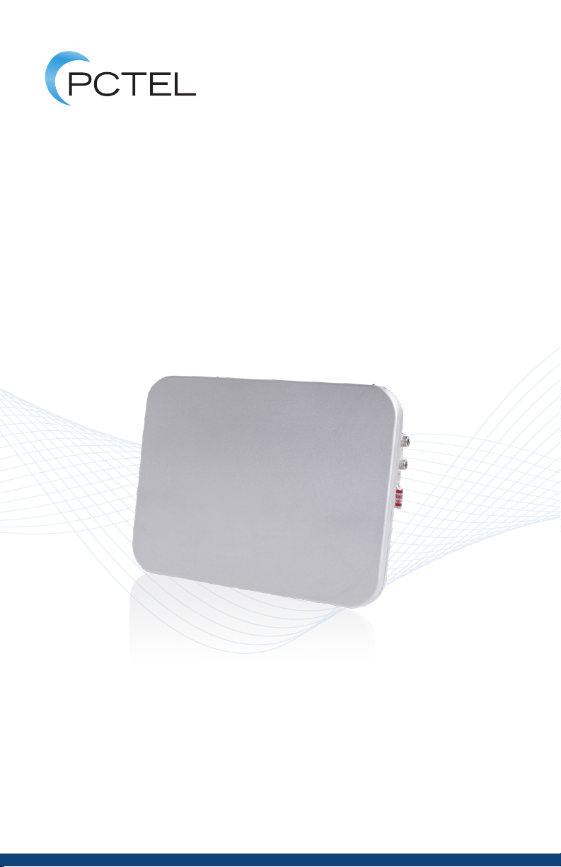
OPERATION GUIDE
AP-WiFi-1200
Access Point
Rugged Dual-Band 2x2 802.11ac Wave 2 WiFi
AP-WIFI-1200

2
OPERATION GUIDE
Table of Figures
Table of Figures ...................................................................................................................................3
Revision History ..................................................................................................................................3
Text Format Conventions...............................................................................................................3
Terms and Abbreviations ............................................................................................................... 3
Referenced Documents.................................................................................................................. 4
1. Overview ..........................................................................................................................................4
2. Features............................................................................................................................................5
2.1. Summary................................................................................................................................ 5
2.2. AP-WiFi-1200 WiFi Features.......................................................................................... 6
2.3. AP-WiFi-1200 WiFi Summary ........................................................................................ 6
3. Setup and Conguration.........................................................................................................7
3.1. Packing List .......................................................................................................................... 7
3.2. Setup .......................................................................................................................................8
3.3. Web User Interface............................................................................................................ 8
3.4. Radio Conguration ..........................................................................................................9
3.5. Console Interface............................................................................................................ 10
3.6. Factory Conguration.................................................................................................... 11
4. Installation ................................................................................................................................... 12
4.1. Overview ............................................................................................................................. 12
4.2. Antenna Installation ....................................................................................................... 14
4.3. Mounting Bracket Installation.................................................................................... 15
4.3.1. Wall Mounting...................................................................................................... 15
4.3.2. Pole Mounting...................................................................................................... 16
4.4. Grounding .......................................................................................................................... 17
5. Compliance ................................................................................................................................. 18
6. Safety Notices............................................................................................................................ 19
7. Product Usage ........................................................................................................................... 20

3
OPERATION GUIDE
Table of Figures
Figure 1 Features Summary...........................................................................................................5
Figure 2 Access Point enclosure Top and Bottom views*.............................................. 12
Figure 3 Access Point enclosure Front and Rear views*................................................ 13
Figure 4 Access Point enclosure Left-side and Right-side views*.............................. 14
Figure 5 Access Point wall mounting options* ................................................................... 15
Figure 6 Access Point pole mounting options*................................................................... 16
Figure 7 Grounding Lug attachment options*..................................................................... 17
Figure 8 Compliance...................................................................................................................... 18
Revision History
Version Description Date
0.2.0 Initial Version September 29, 2020
0.3.0 Updated terms October 12, 2020
0.4.0 Updated installation section Phihong Power November 3, 2020
Injector P.N.
Text Format Conventions
Monotype – Palatino Linotype MONOTYPE, Bold
[Commandprompt,directories,les]
Courier New, Bold
[Console commands and input]
Terms and Abbreviations
OFDM Orthogonal Frequency-division Multiplexing
MU-MIMO Multi-User, Multiple Input, Multiple Output
DSSS Direct Sequence Spread Spectrum
CCK Complementary Code Keying
* This representation of the PCTEL AP-WiFi-1200 enclosure shows the product as currently proposed and is subject to change.

4
OPERATION GUIDE
The PCTEL AP-WiFi-1200 Outdoor Industrial Access Point is a robust solution
designed to meet the challenges of any outdoor or industrial environment. The
2x2 802.11ac Wave 2 WiFi radios operate in both the 2.4 GHz and 5 GHz bands. A
Bluetooth 5.1 radio option is standard. All antennas are external to the enclosure to
provide exibility in selecting the antennas for optimal coverage.
The AP-WiFi-1200 1000/100/10 Mbps wired Ethernet interface provides network
connectivity along with power per the 802.3at Type 1 Class 3 Power over Ethernet
specication. Data rates of 867 Mbps/114 Mbps are achievable over the 5 GHz and
2.4 GHz radios respectively with an aggregate dual-radio rate of up to 1 Gbps. Low
power consumption and high WiFi transmit power make the AP-WiFi-1200 a clear
choice for deployments where high performance is needed.
The compact enclosure weighs just over 3.2 pounds (1.45 kg) and is only
5.79" x 7.84" x 2.50". The AP-WiFi-1200 can be deployed in extreme weather
environments with an operating temperature range between -40°C and +65°C
[+55°C with a full solar loading of 1200 W/m2]. It can also withstand wind gusts up
to 165 mph. An IP-67 rating oers extended dust and water protection in
most conditions.
Deployment is made easy with simple and convenient mounting options.
This Operation Manual covers AP-WiFi-1200 regulatory domain for United States,
Canada and Europe.
Referenced Documents
Document Description Version
PCTEL AP-WiFi-1200 Rugged Dual-Band 2x2 802.11ac 1.0
Access Point Datasheet Wave 2 WiFi
1. Overview

5
OPERATION GUIDE
Parameter Specication
Radios (Dual Band Concurrent) 2.4 GHz: 802.11b/g/n, 2x2:2
5 GHz: 802.11a/n/ac Wave 2, 2x2:2
Channel Bandwidth 2.4 GHz: 20 MHz, 40 MHz
5 GHz: 20/40/80 MHz
TX Power 2.4 GHz: 26 dBm Total, 23 dBm per path
5 GHz: 24 dBm Total, 21 dBm per path
PHY Rate 2.4 GHz: 300 Mbps (40 MHz)
5 GHz: 866.7 Mbps (80 MHz)
Bluetooth 5.1
Memory (DRAM / NAND / NOR) 1 GB / 256 MB / 4 MB
CPU Clock Speed 717 MHz
CPU Cores Quad-Core CPU / 4x ARM Cortex A7 (IPQ4029)
Power Consumption < 13 W
Antenna Ports WiFi: 4 Single Band Ports, N-connectors
Bluetooth: 1 Single Band Port, N-connector
Ethernet Interface 1 GbE (PoE, 802.3at Type 1 Class 3): -13 W
Mode Button Software dened function
Console Port USB 2.0 Type-B Mini
Size 5.79" x 7.84" x 2.50" (148 x 199 x 64 mm)
Temp Range (Operational) -40°C to +65°C
-40°C to +55°C with Full Sun Load
Temp Range (Storage) -40°C to +85°C
Water/Dust Intrusion IP-67
Color Pantone 428C
LED Status Indicator Software dened operation status
Compliance FCC, ISED, ETSI
2. Features
2.1. Summary
Figure 1. Features Summary

6
OPERATION GUIDE
• Supports IEEE 802.11a/b/g/n and ac Wave 2 standards
• Capable of 2x2, two spatial stream communication concurrently on the 2.4 and
5 GHz bands
• Supports 20/40 MHz at 2.4 GHz and 20/40/80 MHz at 5 GHz
• Supports up to 256 QAM
• Data rates of up to 867 Mbps in 802.11ac 80 MHz channels using reduced
(short) guard interval (SGI)
• Supports Multiuser MIMO (MU-MIMO) technology
• Supports Dynamic Frequency Selection (DFS) in required 5 GHz bands
• Maximal likelihood (ML) decoding
• Spatial multiplexing, cyclic-delay diversity (CDD), low-density parity check
(LDPC), maximal ratio combining (MRC), and space-time block coding (STBC)
• AMSDU and AMPDU frame aggregation
• Compatible with software encryption of AES at 128/256 bits and DES/3DES
• Compatible with WEP, TKIP hardware encryption or WAPI hardware encryption
This SoC implements half-duplex OFDM on both the 2.4 GHz and 5 GHz radios.
The 5 GHz radio supports up to 867 Mbps when congured in 802.11ac mode
with an 80 MHz bandwidth and short guard interval. It also supports data rates
and mandatory features for the 802.11a, 802.11n, and 802.11ac standards. The
802.11ac features supported include explicit transmit beamforming, implicit
transmit beamforming, MU-MIMO, dynamic bandwidth switching, maximal
likelihood decoding, low-density parity check, maximal ratio combining, space-time
block coding.
The 2.4 GHz radio supports up to 300 Mbps when congured in 802.11n mode
with a 40 MHz bandwidth and short guard interval. It also supports data rates and
mandatory features for the 802.11b, 802.11g, and 802.11n standards. This includes
DSSS and CCK data rates for the 802.11b standard and OFDM data rates for the
802.11g and 802.11n standards. Support for Multiple Input Multiple Output (MIMO)
with multiple spatial streams and 20 or 40 MHz bandwidths are included per the
802.11n standard.
2.2. AP-WiFi-1200 WiFi Features
2.3. AP-WiFi-1200 WiFi Summary

7
OPERATION GUIDE
The PCTEL AP-WiFi-1200 is designed for ease of setup and conguration. Out of
the box, only settings that are particular to system integration need to be changed
as needed. A Web User Interface is provided for access to all system settings.
Several typical changes are shown below. See Section 3.5 for details on the
Console Interface.
The pushbutton switch provides two functions. A momentary press of the button
will indicate WPS mode. Holding the button for at least ve seconds will reset the
access point to factory settings.
The access point status is provided by the LED Status Indicator built into the
weatherproof pushbutton switch. After power is successfully applied, under normal
operation, the LED Status Indicator is green.
Note: This unit can only be congured to operate as an access point. Since the
access point can be installed either indoors or outdoors, it can be operated as either
an indoor or outdoor access point. Client mode and bridge mode are not currently
supported. The unit cannot be congured to operate in either of these two modes.
3.1. Packing List
• AP-WiFi-1200 Access Point
• Antennas
-(3) 2.4 GHz 6 dBi Omni Antenna - Part Number BOA24006NM
- (2) Dual band 7 dBi Antenna (for 5 GHz radio) - Part Number MHODB24490507NM-IP
• Phihong POE29U-1AT(PL)D-R Power Injector
• Ethernet Cable
• Console Cable
• Installation Accessory Kit - Part Number 11-1110-01
• Mount Kit - Part Number 11-1109-01
3. Setup and Conguration

8
OPERATION GUIDE
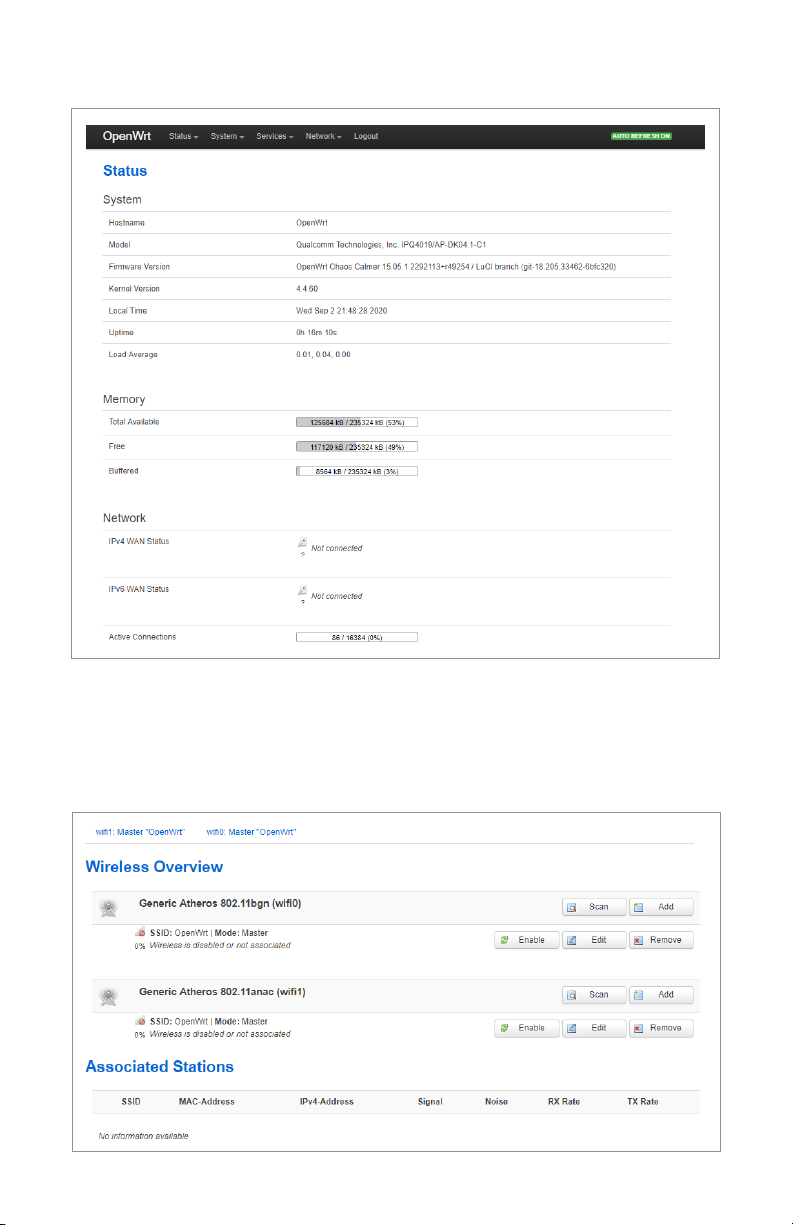
To quickly reach the AP-WiFi-1200 information, access the Web UI portal
by connecting a computer to the Access Point ethernet port and browse to
192.168.1.1. There you will nd everything you need to review the status and
modify factory settings.
The default Username is root. There is no Password set. Be sure to follow the
link to set the Username and Password.
Note: Consider changing the default 192.168.1.1 address so there will not be a
conict once the Access Point is connected to the network.
The Conguration section will explain how to change the Access Point settings.
3.3. Web User Interface
3.2. Setup
Only a few steps need to be taken to setup the AP-WiFi-1200. For convenience,
all the external ports and pushbutton switch are identied on the enclosure. See
Section 4 for installation details.
1. Connect (2) Identied 2.4 GHz WiFi Antennas
2. Connect (2) Identied 5 GHz WiFi Antennas
3. Connect the 2.4 GHz Bluetooth antenna
4. Attach the AP to the Power Injector and connect the Power Injector to the
Ethernet network with the supplied Ethernet cables.
5. Apply power to the Power Injector.
6. The LED Status Indicator will turn on green once the access point is operational.
It may take a minute or more to fully boot the Access Point.
9
OPERATION GUIDE
The PCTEL AP-WiFi-1200 radios can be congured through the Web UI. Be sure
the 2.4 GHz radio and the 5 GHz radio are congured as prescribed by the network.
From the top bar menu, select Network -> WiFi.
3.4. Radio Conguration
10
OPERATION GUIDE
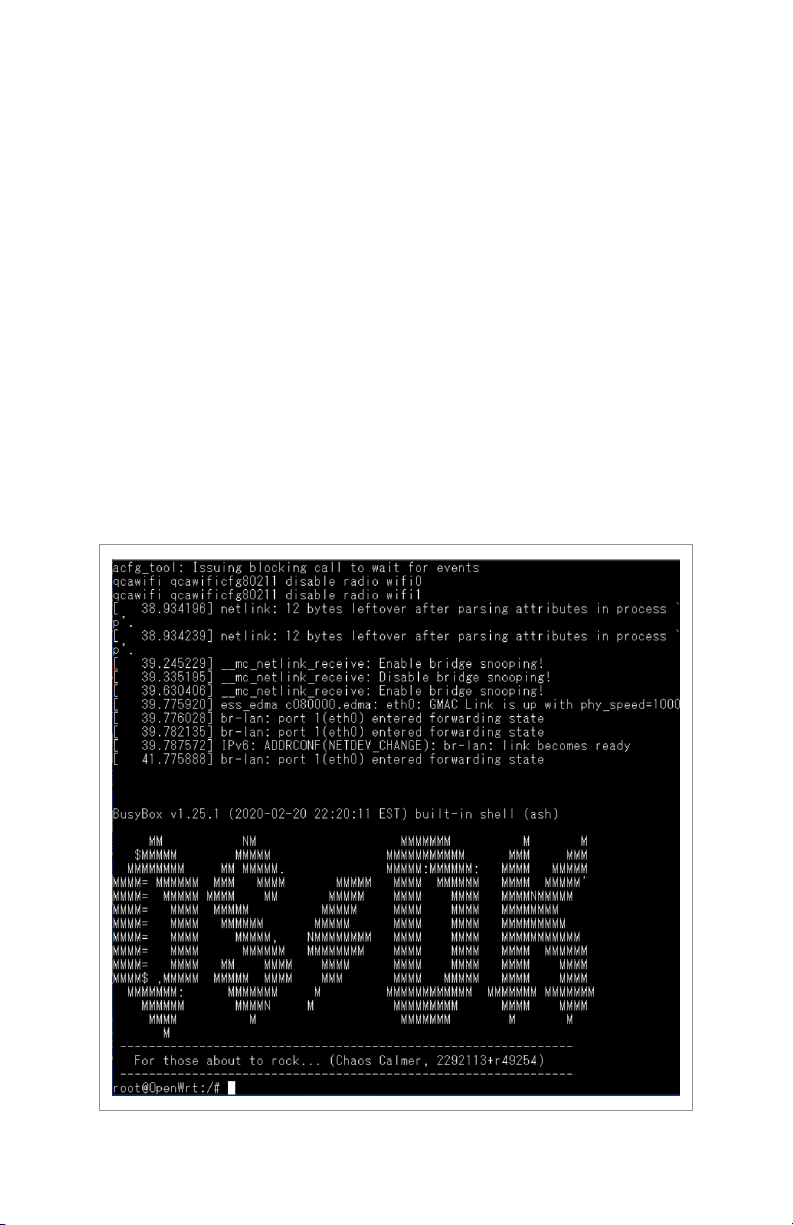
The Console Interface on the AP-WiFi-1200 uses a weatherproof USB Type-B
mini connector. Operating as a serial port, the following settings needed at the
connected computer are listed here.
• Baud rate: 115200
• Data: 8 bits
• Parity: none
• Stop: 1 bit
• Flow control: none
After power up, connect the provided USB cable to a computer.
Note: It is not recommended to connect the USB cable before applying power.
Set up a console tool like Tera Term with the following information.
Here is OpenWRT displayed on the console.
3.5. Console Interface
Indice


