
Pilz PNOZ 8 Manuale utente

PNOZ 8
Operating Manual 22152-EN-03
}Safety relays

Preface
This document is a translation of the original document.
All rights to this documentation are reserved by Pilz GmbH & Co. KG. Copies may be made
for internal purposes. Suggestions and comments for improving this documentation will be
gratefully received.
Source code from third-party manufacturers or open source software has been used for
some components. The relevant licence information is available on the Internet on the Pilz
homepage.
Pilz®, PIT®, PMI®, PNOZ®, Primo®, PSEN®, PSS®, PVIS®, SafetyBUS p®,
SafetyEYE®, SafetyNET p®, the spirit of safety® are registered and protected trademarks
of Pilz GmbH & Co. KG in some countries.
SD means Secure Digital
Contents
Operating Manual PNOZ 8
22152-EN-03 3
Introduction 4
Validity of documentation 4
Using the documentation 4
Definition of symbols 4
Safety 5
Intended use 5
Safety regulations 5
Safety assessment 5
Use of qualified personnel 5
Warranty and liability 6
Disposal 6
For your safety 6
Unit features 7
Safety features 7
Block diagram/terminal configuration 8
Types: AC 8
Type: DC 8
Function Description 9
Operating modes 9
Timing diagram 10
Installation 10
Wiring 11
Preparing for operation 12
Operation 14
Status indicators 15
Faults – Interference 15
Dimensions in mm 15
Technical details 16
Safety characteristic data 20
Supplementary data 21
Service life graph 22
Order reference 22
EC declaration of conformity 22
PNOZ 8
Operating Manual PNOZ 8
22152-EN-03 4
Introduction
Validity of documentation
This documentation is valid for the product PNOZ 8. It is valid until new documentation is
published.
This operating manual explains the function and operation, describes the installation and
provides guidelines on how to connect the product.
Using the documentation
This document is intended for instruction. Only install and commission the product if you
have read and understood this document. The document should be retained for future ref-
erence.
Definition of symbols
Information that is particularly important is identified as follows:
DANGER!
This warning must be heeded! It warns of a hazardous situation that poses
an immediate threat of serious injury and death and indicates preventive
measures that can be taken.
WARNING!
This warning must be heeded! It warns of a hazardous situation that could
lead to serious injury and death and indicates preventive measures that can
be taken.
CAUTION!
This refers to a hazard that can lead to a less serious or minor injury plus
material damage, and also provides information on preventive measures
that can be taken.
NOTICE
This describes a situation in which the product or devices could be dam-
aged and also provides information on preventive measures that can be
taken. It also highlights areas within the text that are of particular import-
ance.
PNOZ 8
Operating Manual PNOZ 8
22152-EN-03 5
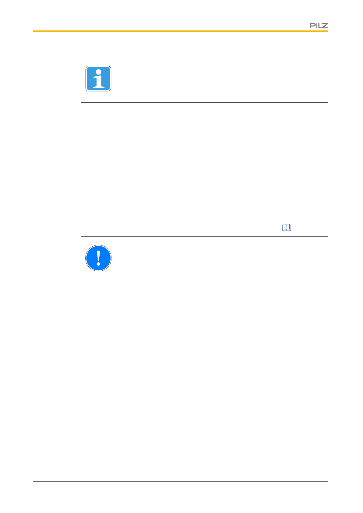
INFORMATION
This gives advice on applications and provides information on special fea-
tures.
Safety
Intended use
The safety relay PNOZ 8 provides a safety-related interruption of a safety circuit.
The safety relay meets the requirements of EN 60947-5-1, EN 60204-1 and VDE 0113-1
and may be used in applications with
}E-STOP pushbuttons
}Safety gates
The following is deemed improper use in particular:
}Any component, technical or electrical modification to the product
}Use of the product outside the areas described in this manual
}Use of the product outside the technical details (see Technical details [ 16]).
NOTICE
EMC-compliant electrical installation
The product is designed for use in an industrial environment. The product
may cause interference if installed in other environments. If installed in other
environments, measures should be taken to comply with the applicable
standards and directives for the respective installation site with regard to in-
terference.
Safety regulations
Safety assessment
Before using a unit it is necessary to perform a safety assessment in accordance with the
Machinery Directive.
Functional safety is guaranteed for the product as a single component. However, this does
not guarantee the functional safety of the overall plant/machine. In order to achieve the re-
quired safety level for the overall plant/machine, define the safety requirements for the
plant/machine and then define how these must be implemented from a technical and organ-
isational standpoint.
Use of qualified personnel
The products may only be assembled, installed, programmed, commissioned, operated,
maintained and decommissioned by competent persons.

PNOZ 8
Operating Manual PNOZ 8
22152-EN-03 6
A competent person is someone who, because of their training, experience and current pro-
fessional activity, has the specialist knowledge required to test, assess and operate the
work equipment, devices, systems, plant and machinery in accordance with the general
standards and guidelines for safety technology.
It is the company’s responsibility only to employ personnel who:
}Are familiar with the basic regulations concerning health and safety / accident preven-
tion
}Have read and understood the information provided in this description under "Safety"
}And have a good knowledge of the generic and specialist standards applicable to the
specific application.
Warranty and liability
All claims to warranty and liability will be rendered invalid if
}The product was used contrary to the purpose for which it is intended
}Damage can be attributed to not having followed the guidelines in the manual
}Operating personnel are not suitably qualified
}Any type of modification has been made (e.g. exchanging components on the PCB
boards, soldering work etc.).
Disposal
}In safety-related applications, please comply with the mission time TM in the safety-re-
lated characteristic data.
}When decommissioning, please comply with local regulations regarding the disposal of
electronic devices (e.g. Electrical and Electronic Equipment Act).
For your safety
The unit meets all the necessary conditions for safe operation. However, please note the
following:
}Note for overvoltage category III: If voltages higher than low voltage (>50 VAC or >120
VDC) are present on the unit, connected control elements and sensors must have a
rated insulation voltage of at least 250 V.

PNOZ 8
Operating Manual PNOZ 8
22152-EN-03 7
Unit features
}Positive-guided relay outputs:
– 3 safety contacts (N/O), instantaneous
– 1 auxiliary contact (N/C), instantaneous
}2 semiconductor outputs
}Connection options for:
– E-STOP pushbutton
– Safety gate limit switch
– Start button
}Reset button for resetting after a short circuit
}LED indicator for:
– Supply voltage
– Switch state of the safety contacts
– Error
}Semiconductor outputs signal:
– Switch state of the safety contacts
– Error
}See order reference for unit types
Safety features
The safety relay meets the following safety requirements:
}The circuit is redundant with built-in self-monitoring.
}The safety function remains effective in the case of a component failure.
}The correct opening and closing of the safety function relays is tested automatically in
each on-off cycle.

PNOZ 8
Operating Manual PNOZ 8
22152-EN-03 8
Block diagram/terminal configuration
Types: AC
}UB: 110 VAC; Order no. 774764
}UB: 230 VAC; Order no. 774768
Y37
Y36
A1 A2 S52
Feed-
back/
Start
*Insulation between the non-marked area and the relay contacts: Basic insulation (over-
voltage category III), Protective separation (overvoltage category II)
Type: DC
}UB: 24 VDC; Order no. 774760
Y37
A1 A2 Y36 S52
A3
Feed-
back/
Start
*Insulation between the non-marked area and the relay contacts: Basic insulation (over-
voltage category III), Protective separation (overvoltage category II)

PNOZ 8
Operating Manual PNOZ 8
22152-EN-03 9
Function Description
The safety relay PNOZ 8 provides a safety-oriented interruption of a safety circuit. When
supply voltage is supplied the "POWER" LED is lit. The unit is ready for operation when the
feedback loop Y1-Y2 and the start circuit S12-Y1 are closed.
}Input circuit is closed (e.g. E-STOP pushbutton not operated):
– Safety contacts 13-14, 23-24 and 33-34 are closed, auxiliary contact 41-42 is open.
The unit is active.
– The LEDs "CH.1" and "CH.2" are lit.
– A high signal is present at the semiconductor output switch state Y32.
}Input circuit is opened (e.g. E-STOP pushbutton operated):
– Safety contacts 13-14, 23-24 and 33-34 are opened redundantly, auxiliary contact
41-42 is closed.
– The LEDs "CH.1" and "CH.2" go out.
– A low signal is present at the semiconductor output switch state Y32.
Semiconductor output fault Y35
}A low signal is present at semiconductor output Y35 if the supply voltage is present and
the internal fuse (circuit breaker) has not blown. If there is a fault on the safety relay, a
high signal is present at Y35, the "FAULT" LED lights. Once the cause of the fault has
been removed, the fuse must be reset via the reset pushbutton.
Operating modes
}Single-channel operation: No redundancy in the input circuit, earth faults in the start
and input circuit are detected.
}Dual-channel operation with detection of shorts across contacts: Redundant input cir-
cuit, PNOZ 8 detects
– earth faults in the start and input circuit,
– short circuits in the input circuit,
– shorts across contacts in the input circuit.
}Dual-channel operation without detection of shorts across contacts: Redundant input
circuit, detects PNOZ 8
– earth faults in the start and input circuit,
– short circuits in the input circuit.
}Automatic start: Unit is active once the input circuit has been closed.
}Manual start: Unit is active once the input circuit and the start circuit are closed.
}Monitored start: Unit is active once
– the input circuit is closed and then the start circuit is closed and opened again.
– the start circuit is closed and then opened again once the input circuit is closed.
}Increase in the number of available contacts by connecting contact expander modules
or external contactors/relays.
PNOZ 8
Operating Manual PNOZ 8
22152-EN-03 10
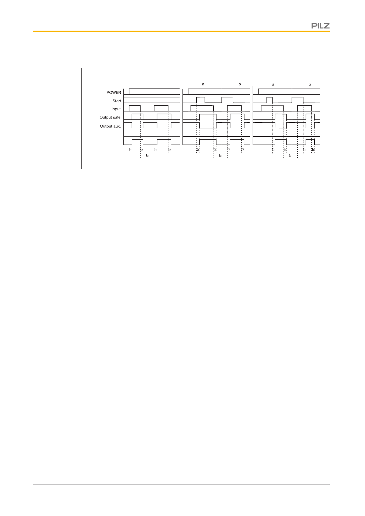
Timing diagram
Out semi OUT
Out semi FAULT
[2] [3][1]
Legend
}Power: Supply voltage
}Start: Start circuit
}Input: Input circuit
}Output safe: Safety contacts
}Output aux: Auxiliary contacts
}Out semi FAULT: Semiconductor output fault
}Out semi OUT: Semiconductor output switch state
}[1]: Automatic start
}[2]: Manual start
}[3]: Monitored start
}a: Input circuit closes before start circuit
}b: Start circuit closes before input circuit
}t1: Switch-on delay
}t2: Delay-on de-energisation
}t3: Recovery time
Installation
}The unit should be installed in a control cabinet with a protection type of at least IP54.
}Use the notch on the rear of the unit to attach it to a DIN rail.
}Ensure the unit is mounted securely on a vertical DIN rail (35 mm) by using a fixing ele-
ment (e.g. retaining bracket or an end angle).
Altri manuali per PNOZ 8
1
Indice
Altri manuali Pilz Staffetta

Pilz
Pilz P2HZ 5 Manuale utente

Pilz
Pilz PNOZ X11P Manuale utente

Pilz
Pilz PNOZ X2.1VP Manuale utente

Pilz
Pilz PNOZ 2 22151-3FR-03 Manuale utente

Pilz
Pilz PNOZX4 Manuale utente

Pilz
Pilz PNOZ pps1p Manuale utente

Pilz
Pilz PNOZ X2P Manuale utente

Pilz
Pilz PNOZ s7 Manuale utente

Pilz
Pilz PNOZ X9 Manuale utente

Pilz
Pilz PNOZ X10 Manuale utente

Pilz
Pilz PNOZ c2 Manuale utente

Pilz
Pilz PNOZ 10 Manuale del proprietario

Pilz
Pilz 22 772-04 Manuale utente

Pilz
Pilz PNOZ XV3.1P Manuale utente

Pilz
Pilz PNOZ XV3.1 Manuale utente

Pilz
Pilz PNOZ 16S Manuale utente

Pilz
Pilz PNOZ s9 Manuale utente

Pilz
Pilz PNOZ XV3.3P Manuale utente

Pilz
Pilz 20407-6NL-06 Manuale utente

Pilz
Pilz PNOZ X3P Manuale utente


