
Posi Pin CR-R885-SB Manuale utente

PIN and Proximity Reader
Stand-alone System
(CR-R885-S and CR-R885-SB)
Installation and Operating Instructions


PosiPin 1
TABLE OF CONTENTS
Installation ..........................................................................2
Mounting and Wiring ................................................................2
Mounting on Metal Surfaces .....................................................2
Technical Specifications ...........................................................3
Feedback ..................................................................................5
Resetting to Default ..................................................................5
Card Presentation Test ............................................................5
System Programming ........................................................6
Section [001] Card/Code Options .............................................6
Section [002] Door Lock Control ..............................................7
Section [003] Access Granted Options ....................................7
Section [004] Display on Card Read ........................................8
Section [005] Keypad Lockout ..................................................9
Section [101] Buzzer Setting ....................................................9
Section [102] Face Light Intensity ............................................9
Section [103] Face Light Operation ..........................................9
Section [104] Face Light Colour .............................................10
Section [200] Changing the Installer Code .............................10
Resetting the Installer and Master Codes to Default ..............10
Master Programming .......................................................11
Sections [201] and [202] Changing the Master Codes ...........11
Section [203] User Code Programming ..................................11
Deleting a User Code .............................................................13
Section [204] User Code Reset ..............................................14
User Operation .................................................................15
User Access ...........................................................................15
Panic Alarm ............................................................................16
User Code Table ...............................................................17
Warranty ............................................................................19

2 Installation and Operating Instructions
INSTALLATION
To select an installation site:
• Avoid wiring the PosiPin cables in the same conduit as AC power cables,
lock power or signal wiring.
• Reader wiring must remain a minimum of 30cm (12in) away from other
wiring, such as wiring for AC power, computer data, telephones, electric
locks, etc.
• Avoid sites within 1.1m (3.5ft) of computer monitors or CRTs.
• Avoid sites near sources of broad spectrum EMI noise, such as motors,
pumps, generators, DC to AC converters, AC switching relays, power
supplies and light dimmers.
• Avoid sites near potential sources of RF signals, such as cellular phones,
two-way radios, etc.
MOUNTING AND WIRING
Use the mounting plate as a guide to drill two holes to secure the mounting
plate and a hole for the cable 0.95cm to 2.54cm (0.375in to 1in) wide. Place
a grommet around the edge of the hole for the cable. Prepare PosiPin’s
cable by cutting the cable jacket back 3.175cm (1.25in) and stripping the
wires back 0.635cm (0.25in). Splice PosiPin’s wires with a recommended
cable wire (see page 5) and connect as shown in Figure 1 on page 4.
MOUNTING ON METAL SURFACES
Although the read range may decrease, PosiPin can be mounted on metal.
However, do not box in or surround the card reader with any kind of metal.
If the reader must be installed in a metal enclosure, ensure that the face of
the card reader is not covered and that at least 1.6" (4cm) remain between
the card reader and the metal on all sides of the card reader.

PosiPin 3
TECHNICAL SPECIFICATIONS
Input Voltage: Typical: 13.8VDC, min.: 11.0VDC, max: 14.5VDC
Input Current: Typical: 65mA @ 12.5VDC, with card: 105mA
Consumption: Typical: 812mW @ 12.5VDC, with card 1.31mW
Frequency: Exciter Field: 125KHz Pulse Modulated, receive low:
12.500KHz, Receive high: 15.625KHz
Operating Temp: -35°C (-31°F) to +65°C (+149°F)
Cable Distance: 152.4m (500ft.)
Suggested Cables: 22AWG, 0.8mm, Multi-conductor, Alpha 5196, 5198
18AWG, 1.2mm, Multi-conductor, Alpha 5386, 5388
Belden 9553, 18AWG, 6-conductor, stranded w/
overall shield
Indicators: Beeper, red LED and green LED
For CR-R885-S: red and green Face Light
For CR-R885-SB: blue and green Face Light
Weight: 280g (9.8 oz.)
Material: Black, UV resistant, ABS plastic
Dimensions: 99.5mm (5.75in.) x 118.5mm (2in.) x 19.5mm (1in.)

4 Installation and Operating Instructions
Figure 1: Connection drawing
PosiPin 5
FEEDBACK
Depending on the programming mode chosen, the feedback will differ. In
the section System Programming on page 6 and Master Programming on
page 11, the combinations of visual feedback and beep tones are specified
step by step.
Visual Feedback: When information is entered on the reader’s keypad, the
red and/or green LEDs will flash, remain constant or extinguish depending
on the step reached in programming.
Confirmation Beep: When an operation is successfully entered, the
reader emits a rapid series of beep tones (“beep-beep-beep-beep-beep”).
Rejection Beep: When the system reverts to a previous status or an
operation is incorrectly entered, the reader emits one long beep tone
(“beeeeeeeeeep”).
RESETTING TO DEFAULT
To reset all sections to factory defaults, disconnect reader’s power supply.
Press and hold the [1] and [2] keys simultaneously while re-connecting its
power supply. Sections are reset when the reader emits a confirmation
beep.
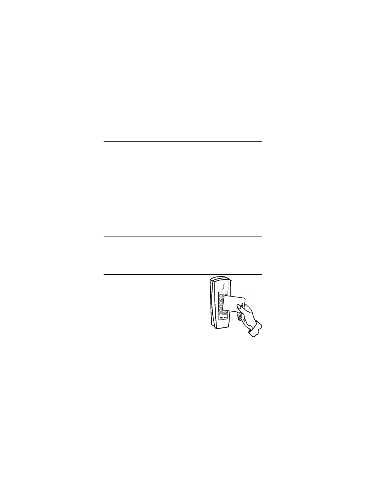
CARD PRESENTATION TEST
Place the card parallel to the PosiPin reader (as
shown in the figure) and move it toward the
reader until the reader provides audio or visual
feedback.

6 Installation and Operating Instructions
SYSTEM PROGRAMMING
The Installer code (default: 000000) can program a new Installer Code PIN
in section [200] and program all the system sections from [001] to [005]
and [101] to [104].
SECTION [001] CARD/CODE OPTIONS
PosiPin can function as a reader only, as a keypad only or as a combined
reader and keypad. Option [3] by default
When a Card/Code option is set, it may require several seconds for
the system to update the programming. The reader emits a
confirmation beep once the modification is complete.
To enter System Programming Mode:
1. Press and hold the [CLEAR]key for 4 seconds.
The reader emits a confirmation beep, the green LED illuminates and
the red LED extinguishes.
2. Enter the [INSTALLER CODE]and press the [ENTER]key.
Reader emits a confirmation beep and the green LED flashes.
3. Enter the 3-digit [SECTION]and press the [ENTER]key.
Reader emits a confirmation beep and green LED becomes constant.
4. Enter the required [DATA]and press the [ENTER]key.
The reader emits a confirmation beep and the green LED flashes.
5. To program another section, repeat steps 2 and 3. To exit, press
and hold the [CLEAR]key for 4 seconds.
The reader emits a rejection beep and the green LED extinguishes.
Enter Description
[0] Keypad and reader disabled. For programming only.
[1] Reader only. Present valid card to the reader for Access Granted.
[2] Keypad only. Enter valid code on the keypad for Access Granted.
[3] Keypad and reader enabled. A user must present BOTH a valid
card AND enter a valid code to receive an Access Granted.

PosiPin 7
SECTION [002] DOOR LOCK CONTROL
The Door Lock Control determines the length of time the locking device
remains unlatched after an Access Granted. When [0] is programmed, the
lock is unlatched after an Access Granted and remains unlatched until it
receives a second Access Granted (functions like a key). When [1] to [5] is
programmed, the lock remains unlatched for the defined time period.
Option [2] by default.
SECTION [003] ACCESS GRANTED OPTIONS
The Access Granted Options depend on the Card/Code Options set in
section [001]. Option [0] by default.
Single Access Granted
When [0] is programmed, one user can obtain Access Granted by using a
valid card, code or both depending on the Card/Code Option set.
Enter Description
[0] Card/Code Controlled Free Access (Latched)
[1] 1 second
[2] 5 seconds
[3] 10 seconds
[4] 20 seconds
[5] 60 seconds
Enter Description
[0] Single Access Granted
[1] Dual Access Granted
[2] Dual Access Granted with Dual Panic Disarm

8 Installation and Operating Instructions
Dual Access Granted
When [1] is programmed, two users are required to obtain Access Granted.
Each user must use a validcard, code or both dependingon the Card/Code
Option set. Only one user is required to disarm a Panic Alarm.
Example: When the reader and the keypad are enabled, User 1 must
present a valid card and enter a valid code and then User 2 must present
a valid card and enter a valid code for Access Granted.
Dual Access Granted with Dual Panic Disarm
When [2] is programmed, two users are required to obtain Access Granted
(same as Dual Access Granted) and two users are required to disarm a
Panic Alarm.
For example, a Panic Alarm is triggered, User 1 must present a valid card
and enter a valid code and then User 2 must present a valid card and enter
a valid code to disarm the alarm.
SECTION [004] DISPLAY ON CARD READ
The visual feedback when a card is presented to the reader can be
adjusted according to the installation’s requirements. Option [3] by default.
Enter Description
[0] Display on Card Read disabled
[1] Red Status LED flashes
[2] Green Status LED flashes
[3] Red and green Status LEDs flash
[4] Face Light flashes
[5] Face Light and red Status LED flash
[6] Face Light and green Status LED flash
[7] Face Light and both Status LEDs flash
Questo manuale è adatto per i seguenti modelli
1
Indice
Altri manuali Posi Pin Lettore di schede


