Presentation Switchers PS510 Manuale utente

Presentation
Switchers
Series 500
Installation Guide
PS510
Under Table
Presentation Switcher
October, 2012 • PN: DOC-000005-00A

Page 2 Presentation Switchers, Inc.
Trademark Informaon
Trademark Informaon
Presentaon Switchers®, the “PS Box” logo or icon, and the names and marks associated with Presentaon
Switchers’ products are trademarks and/or service marks of Presentaon Switchers, Inc., and are registered
and/or common-law marks in the United States and various other countries.
All other trademarks are the property of their respecve owners.
Patent Informaon
Patent Informaon
The accompanying product is protected by one or more U.S. and foreign patents and/or pending patent
applicaons held by Presentaon Switchers, Inc.
Customer Feedback
Customer Feedback
We are constantly working to improve the quality of our documentaon, and we would appreciate your
feedback. Please send email to markeƟng@PresentaƟonSwitchers.com.
© 2012 Presentaon Switchers, Inc. All rights reserved.
Presentaon Switchers, Inc.
15364 E. Valley Blvd.
City of Industry, CA 91746 USA
No part of this document may be reproduced or transmied in any form or by any means, electronic or
mechanical, for any purpose, without the express wrien permission of Presentaon Switchers, Inc. Under
the law, reproducing includes translang into another language or format.
Every effort has been made to ensure that the informaon in this manual is accurate. Presentaon Switch-
ers, Inc., is not responsible for prinng or clerical errors.
Informaon in this document is subject to change without noce.

Page 3Series 500 Installation Guide
Contents
Contents............................................................................................3
Getting Started..................................................................................5
Installation Guide Overview.....................................................................................................5
Package Contents.....................................................................................................................5
Installation Tools.......................................................................................................................5
Inserting Input Cards .......................................................................6
Inserting an Input Board Assembly.........................................................................................6
Pre-Drill Mounting Holes..................................................................8
Locating the Switcher...............................................................................................................8
Pre-Drill Mounting Holes As Shown........................................................................................8
Connecting Devices.........................................................................9
Input Devices / Sources............................................................................................................9
Connecting Display or Video Output Devices........................................................................9
Connecting Audio Output Devices........................................................................................10
Connecting Control Devices..................................................................................................11
Configuring the PS510...................................................................12
The Configuration Software...................................................................................................12
Uploading the Settings...........................................................................................................14
Save or Retrieve Settings.......................................................................................................14
PS500 Display Control...................................................................15
Main Form................................................................................................................................15
Relay Form...............................................................................................................................16
Test Form.................................................................................................................................16
Connecting to the Switcher....................................................................................................17
Setting Communication Baud Rates.....................................................................................17
Entering Display Codes..........................................................................................................17
Input Select..............................................................................................................................18
No Signal Power Off................................................................................................................18
Time Between Commands......................................................................................................18
No Activity Power Off..............................................................................................................18

Page 4 Presentation Switchers, Inc.
Relay / Contact Closure Enable Flag.....................................................................................19
Mode.........................................................................................................................................19
Testing the Display Codes......................................................................................................20
Testing the Relays...................................................................................................................20
Testing the Complete System................................................................................................21
Enabling or Disabling the Display Control Feature .............................................................21
Appendix.........................................................................................22
Series 500 Programming Codes............................................................................................23

Page 5Series 500 Installation Guide
Getting Started
Installation Guide Overview
Installation Guide Overview
This manual will provide detailed instrucons to assist an installer with a typical under table in-
stallaon of a PS510 presentaon switcher. This process is best outlined by the following steps.
1. Unpack the switcher from the box and separate all components.
2. Install input cards (if necessary)
3. Locate and pre-drill mounng holes.
4. Mount the switcher under the table.
5. Aach input and output devices to the switcher.
6. Power up the unit and test the unit manually.
7. Make adjustments to the system as necessary.
8. Test the system again using external control devices as necessary.
Package Contents
Package Contents
Below is a list of items enclosed in each Series 500 enclosure.
Quantity Description
1 PS510 Presentation Switcher
1 Installation Guide (PN: DOC-000005-xxx) (This manual)
1 5 Connector Terminal Block Stereo Audio Connector, Line Level Audio
6 Wood Screws, #6 X 3/4”, Pan-Head, Philips
1 Power Cord (US Only)
Installation Tools
Installation Tools
• Drill
• 3/32” Drill Bit for Sowood or 7/64” Drill Bit for Hardwood
• #2 Philips Head Screw Driver
• 1/8” Flat Blade “Tweeker” Screw Driver
Page 6 Presentation Switchers, Inc.
Inserting Input Cards
Inserting an Input Board Assembly
Inserting an Input Board Assembly
In the United States and Canada, input cards are installed prior to leaving the factory. In some
countries cards are shipped separately. This secon explains the process necessary to install
input card assemblies into a PS510 presentaon switcher.
WARNING: While “hot swapping” of input cards is possible, it is recommended to discon-
nect power from the PS510 enclosure to prevent accidental shock to yourself or to the
equipment.
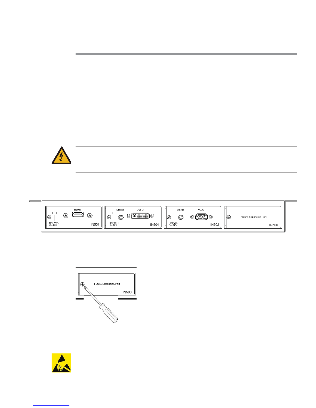
The drawing below shows a sample layout of a PS510 enclosure. In this case, the system type is
a PS510 with HDMI, DVI, and VGA inputs.
1. Using a #1 Philips Head screw driver, remove the screw that holds the IN500 - Future Expan-
sion Plate in place.
2. Unpackage the new input board assembly from the shipping container and set aside.
CAUTION: This product, like all microcontroller products, uses semiconductors that can be
damaged by electrostac discharge (ESD). When handling, care must be taken so that the de-
vice is not damaged. Damage due to inappropriate handling is not covered by the warranty.

Page 7Series 500 Installation Guide
The following precauons must be taken.
a. Do not open the protecve conducve packaging unl you have read the following, and
are at an approved an-stac work staon.
b. Always discharge yourself by touching a grounded bare metal surface before picking up
an ESD - sensive electronic component.
3. Remove the input board assembly from the protecve conducve packaging.
4. Insert the new input board assembly into the enclosure while aligning card within the
guides on the leand right of the opening. Press the card firmly (about 10 lbs of force) into
the card slot.
5. Using the screw extracted from the IN500 Future Expansion plate, fasten the new input
board assembly in place.
6. Connect power cord to enclosure and turn system on.
7. The system is now ready for use and the new input is acve.
Page 8 Presentation Switchers, Inc.
Pre-Drill Mounting Holes
Locating the Switcher
Locating the Switcher
Locate the switcher under the table toward the center line of the table. Ensure switcher is far
away from potenal contact with people’s legs or knees.
WARNING: Keep product away from potenal contact with human legs, knees, and other
body parts. A PS510 is made of metal and can harm people if struck with sufficient force.
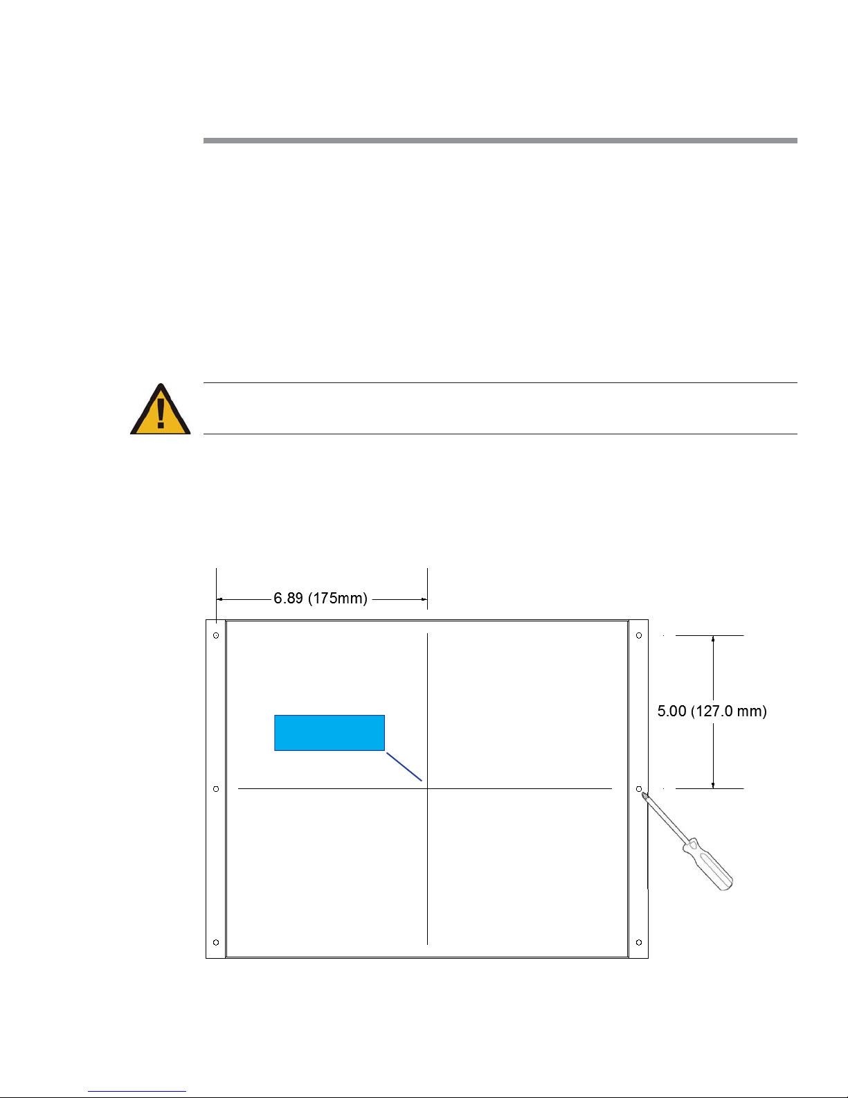
Pre-Drill Mounting Holes As Shown
Pre-Drill Mounting Holes As Shown
1. Using a 3/32” drill (for sowood) or 7/64” drill (for hardwood), drill each hole approximately
5/8” in depth.
2. Using #2 Phillips screw driver, fasten all 6 screws.
Center Line of
PS510
Page 9Series 500 Installation Guide
Connecting Devices
Input Devices / Sources
Input Devices / Sources
Connect input devices or audio-visual sources as you would most AV Receivers. In most cases,
one source is connected per input board assembly and includes both the video and audio com-
ponents.
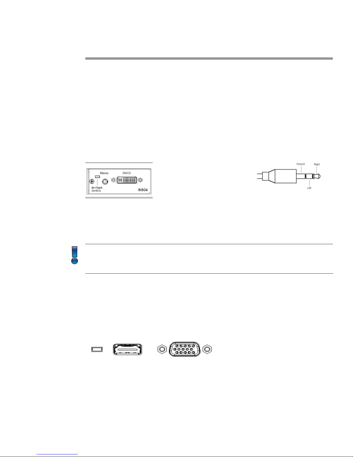
In the example above, a DVI-D board, part number IN504 in this case, is located in input slot
number 2. Connect the video poron to the DVI connector and the audio component to the
3.5mm connector located just above the video connector. This device is now considered “Input
#2”.
Note: The LED located just above the stereo connector will illuminate red when power is
present on the card. The LED will illuminate green when an acve video signal is recognized
on the DVI video connector. This LED is present on most input board assemblies.
Connue the process of connecng input devices unl all sources are aached.
Connecting Display or Video Output Devices
Connecting Display or Video Output Devices
The PS510 presentaon switcher is equipped with HDMI and VGA connectors. These connectors
are located on the opposite side of the input card assemblies.
The HDMI and VGA outputs are simultaneous outputs and output the same resoluons at all
mes.
3.5mm Connector
Page 10 Presentation Switchers, Inc.
EDID and Image Resoluons
EDID and Image Resoluons
By default, image resoluon is set to XGA (1024 X 768) using Table Select mode. The installer
can override this feature by selecng an image resoluon from a table or by selecng EDID
Passthru Mode.
In Passthru mode, the source negoates directly with the display device to determine the best
possible display resoluon.
Audio on HDMI Connector
Audio on HDMI Connector
When connecng to the HDMI connector, audio from the input device or source selected will
pass directly to the display device. This includes audio from analog sources that are digized
and embedded onto the HDMI stream.
HDCP Encrypted Sources
HDCP Encrypted Sources
Signals which are encrypted using HDCP will pass directly to the HDMI connector in all situa-
ons. The VGA connector will indicate a disconnected signal and audio will not be present on
the Line Level output.
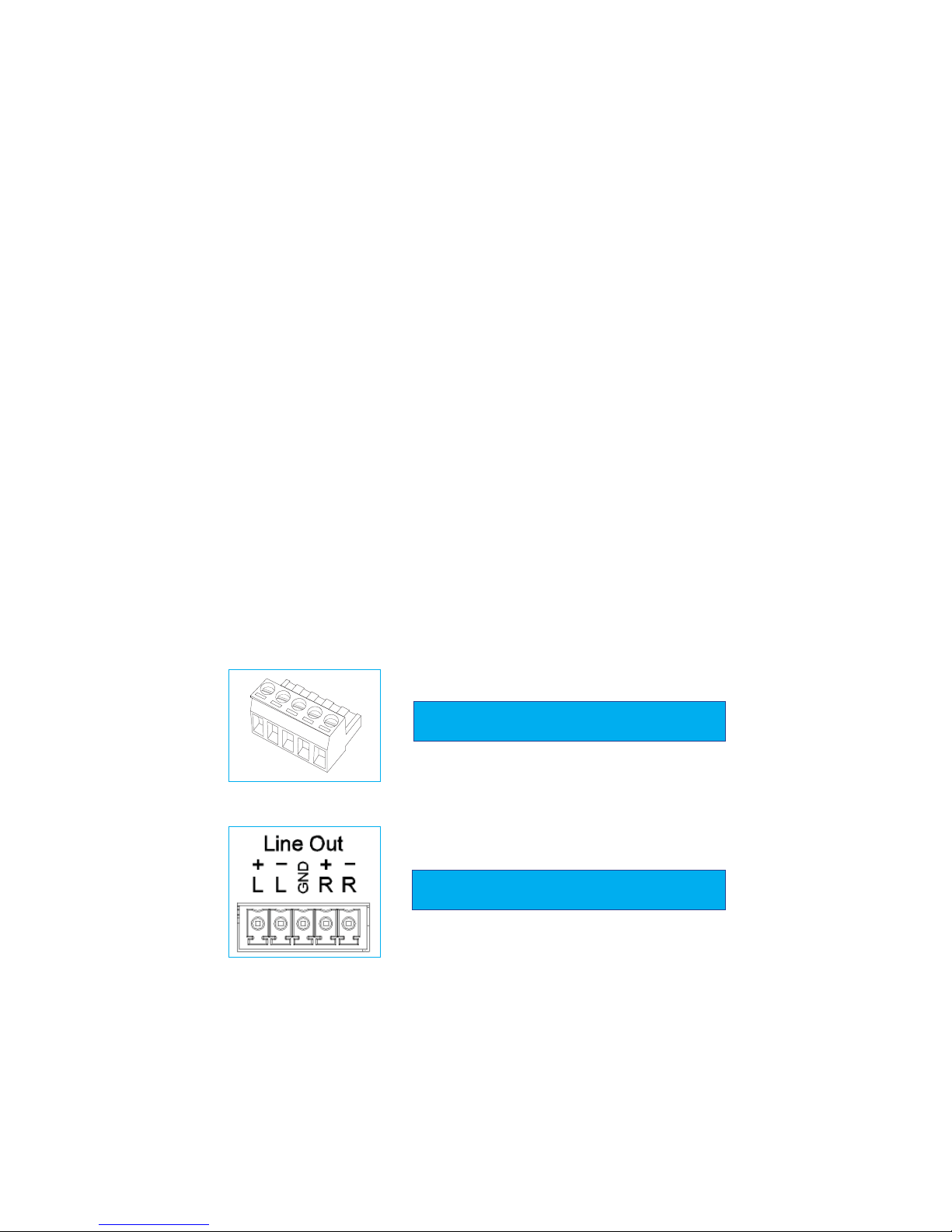
Connecting Audio Output Devices
Connecting Audio Output Devices
The PS510 is equipped with a line level stereo audio output. Line level audio, by default, is a ste-
reo audio balanced output. Using the male audio connectors provided (shown below), connect
the audio signals as indicated below. Tighten with a 1/8” flat head screw driver (tweeker).
Line Out Audio Connector (Male Connector)
Audio Pin Configuration (Female Connector)
Indice
Altri manuali Presentation Switchers Interruttore

Presentation Switchers
Presentation Switchers PS190 Manuale utente

Presentation Switchers
Presentation Switchers PS110 Manuale utente

Presentation Switchers
Presentation Switchers PS120 Manuale utente

Presentation Switchers
Presentation Switchers PS105 Istruzioni operative e di manutenzione

Presentation Switchers
Presentation Switchers PS112 Manuale utente

Presentation Switchers
Presentation Switchers PS190 Manuale utente

Presentation Switchers
Presentation Switchers PS112 Manuale

Presentation Switchers
Presentation Switchers PS190 Manuale

Presentation Switchers
Presentation Switchers PS100 Manuale utente

Presentation Switchers
Presentation Switchers PS120 Manuale utente


