Rave RMC-66P Manuale utente


3
•6 Source Inputs: 3 Stereo RCA, 2 Stereo 3.5mm and 1 Optical Connector
•6 Zone Stereo RCA outputs
•APP Control iOS and Android
•RJ45 Ethernet Connection Ports
•RS-232 Communication Port
•Built-in IR Emitters
•12V DC Trigger Outputs
•Expandable up to 18 Zones
•Zone status LED
•Optional Keypad and IR Remote Control
WWW.RAVETECHNOLOGY.COM
INTRODUCTION
The RMC-66P is a functional, easy-to-install, highly compatible, expandable, and user-friendly
audio distribution system. The RMC-66P provides 6 Source inputs and 6 zones with stereo RCA
preamp outputs. The RMC-66P combined with the optimal power amplifier creates a customized
audio distribution system. With optional expansion cables the RMC-66P is expandable up to 18
zones. This system can be controlled with (optional) keypads, RS232, IR or with the iOS and
Android APP. Enjoy the quality and reliability of your new RAVE Technology RMC-66P.
FEATURES
PACKAGE CONTENT
•RMC-66P Matrix Controller Preamplifier
•Rack Mounting Ears 2 (Installed)
•External Power Supply
•User Manual
•1 IR Remote Control
•1 Expansion Cable
•1 Wall Plate Keypad Hub
•6 Wall Plate Keypads
Note:
RMC-66K (Optional) Accessory Kit
5
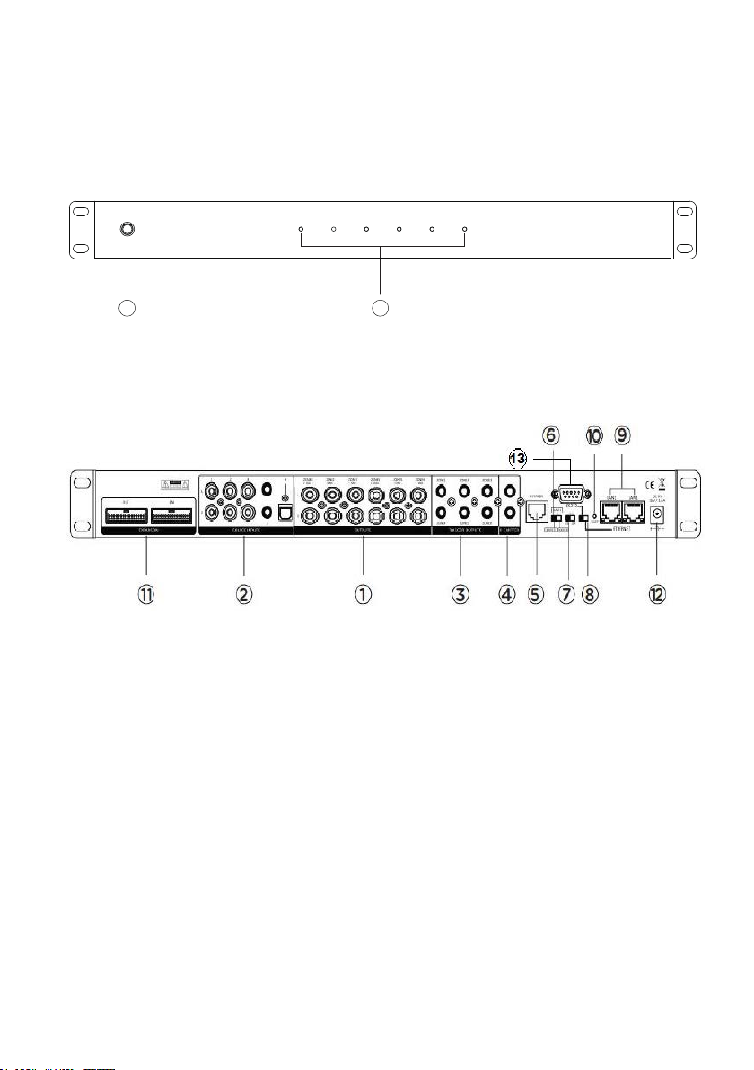
POWER
ZONE 1 ZONE 2 ZONE 3 ZONE 4 ZONE 5 ZONE 6
PRODUCT FEATURES
1. PRE-AMP OUTPUTS
2. SOURCE INPUTS
3. 12V TRIGGER OUTPUTS
4. IR EMITTER OUTPUTS
5. KEYPAD HUB CONNECTION
6. UNIT ID SWITCH (Master-Slave1-Slave2)
7. AUTO GAIN CONTROL
8. COMMUNICATION (Ethernet/RS232)
9. ETHERNET PORTS
10. NETWORK RESET (Factory default)
11. EXPANSION INPUT/OUTPUT
12. POWER SUPPLY INPUT JACK
13. RS232 COMMUNICATION PORT
1. POWER ON/OFF SWITCH
2. LED ZONE STATUS (Blue: Standby-White: ON-Blue/White: Mute)
1
2
WWW.RAVETECHNOLOGY.COM
6
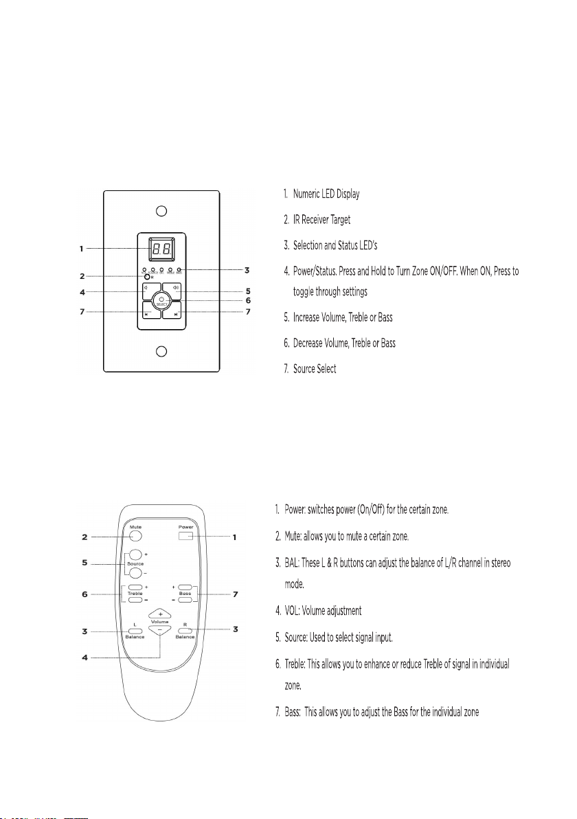
The optional Infrared remote provides zone control of the MRC-66P through the
(IR) receiver located in the center of the keypad. All keypad functions can be
accessed with the remote. An additional mute button to temporarily mute audio in
the zone. The keypad LED display will flash indicating the mute status. Press the
mute button again to return to un-mute the zone.
OGY.COM
WWW.RAVETECHNOLOGY.COM
KEYPAD AND IR REMOTE FEATURES
The optional keypads can control zone power on/off, volume up/down, selection of
sources 1-6, zone treble, zone bass, zone un-mute and zone standby. The
keypads have Infrared receivers which allows control of source devices and the
RMC-66P with the optional IR remote. The IR system can also send IR commands
to the IR output jacks of the RMC-66P for control of your source components.

The RMC-66P has optional POE enabled keypads. This allows for source control
from each specific zone as well as IR routing to the appropriate source devices once
selected. The RMC-66K (Optional Accessory Kit) also comes with a hub that allows
for all 6-keypads to be connected to the RMC-66P via Cat5e/6.
9
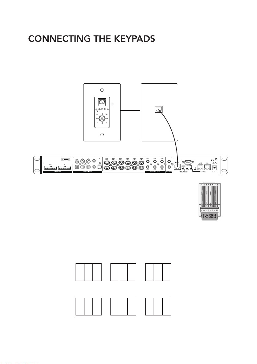
ZONE-1
ON ON OFF
1 2 3
ZONE-2
ON ONOFF
1 2 3
ZONE-3
ON OFFOFF
1 2 3
ZONE-4
ONONOFF
1 2 3
ZONE-5
ON OFFOFF
1 2 3
ZONE-6
ONOFFOFF
1 2 3
WWW.RAVETECHNOLOGY.COM
Without the power being connected, make the keypad hub
connection from the from the RJ45 port on the back of the
RMC-66Pand the front RJ45 port of the hub. 568B termination
standard is recommended.
Next you will need to ensure that each keypad has the proper zone ID assigned.
Please refer to the chart below or the rear panel of the keypad for the dip switch
settings for each zone ID. Set the keypad ID for the zone you want to control.

10
Source 2-DVD
IR Emitter from
Source 2 port
Power
IR Signal
Grounding
IR +
IR -
IR EMITTERS
There are 2 Infrared (IR) emitter outputs on the RMC-66P. These outputs are used to control the
connected source components remotely through the RMC-66P keypad IR receiver.
For example, connect the flasher to the IR output and receiver window of the connected source.
Now you can use your IR remote to control your source through all zones with keypads.
WWW.RAVETECHNOLOGY.COM
CONNECTING THE KEYPAD HUB
FRONT BACK
Expansion Port

11
1. First each unit needs to be addressed using the MASTER/SLAVE switch.
There are 3 positions for this, Master, Slave 1, and Slave 2 to identify each unit.
2. Connect the expansion OUTPUT of the MASTER unit to the INPUT of Slave1
3. Connect the OUTPUT of SLAVE 1 to the INPUT of SLAVE 2.
WWW.RAVETECHNOLOGY.COM
All source audio information - All RS232 control data - All MCU communication from the
master and slave units will be shared through the expansion cable. Each RMC-66P unit
must be connected to the network for APP control.
NOTE: The MASTER unit IR outputs will function as normal however the IR outputs from
SLAVE1 and SLAVE2 will not pass through the MASTER IR outputs.
IR flashers from SLAVE1 and SLAVE2 zones will need to added to source for IR control
of source devices connected to the MASTER unit.
TRIGGER OUTPUTS
There are 6 trigger outputs corresponding to each zone. When a zone
is powered ON the zone sends 12VDC to the trigger output jack. When
the zone is powered OFF the signal is disengaged. Triggers can be
used to power peripheral equipment ON/OFF with the zones.
ZONE EXPANSION

LAN NETWORK CONNECTION
There are 2 Ethernet ports on the rear panel of the RMC-66P for the connecting to the
network and connecting additional RMC-66P or other network devices.
Connect the RMC-66P network LAN port to the LAN port of the Wi-Fi Router.
Connect the 2nd port labeled "to device" to a network device. The to device port
operates like a network switch when LAN port is connected to a network.
Please use a good quality Cat5e/5 cable, and follow the diagram below.
15
OGY.COM
WWW.RAVETECHNOLOGY.COM
When controlling via Network connection, please make sure the ETHERNET/RS232 switch is set at
ETHERNET position. If you are using the RS232 port for control please set the switch to the RS232
position. Connect the RMC-66P network LAN port to the LAN port of the Wi-Fi Router.
NOTE: The network router will automatically set the IP address DHCP default ON.
Please check the local router configuration page for the IP information.
Indice
Altri manuali Rave Amplificatore


