Renogy REGO 500A Manuale utente
VERSION A0
USER MANUAL
500A Combiner Box
REGO
ROA500CB-98
Before Getting Started
The user manual provides important operation and maintenance instructions for REGO
500A Combiner Box (hereinafter referred to as combiner box).
Read the user manual carefully before operation and save it for future reference.
Failure to observe the instructions or precautions in the user manual can result in
electrical shock, serious injury, or death, or can damage the combiner box, potentially
rendering it inoperable.
zRenogy ensures the accuracy, sufficiency, and the applicability of information in
the user manual at the time of printing due to continual product improvements
that may occur.
zRenogy assumes no responsibility or liability for personal and property losses,
whether directly and indirectly, caused by the user’s failure to install and use the
product in compliance with the user manual.
zRenogy is not responsible or liable for any failure, damage, or injury resulting from
repair attempts by unqualified personnel, improper installation, or inappropriate
operation.
zThe illustrations in the user manual are for demonstration purposes only. Details
may appear slightly different depending on product revision and market region.
zRenogy reserves the right to change the information in the user manual without
notice. For the latest user manual, visit renogy.com.
Disclaimer
REGO 500A Combiner Box User Manual © 2023 Renogy. All rights reserved.
RENOGY and are registered trademarks of Renogy.
zAll information in the user manual is subject to copyright and other intellectual
property rights of Renogy and its licensors. The user manual may not be modified,
reproduced, or copied, in whole or in part, without the prior written permissions of
Renogy and its licensors.
zThe registered trademarks in the user manual are the property of Renogy. The
unauthorized use of the trademarks is strictly prohibited.
Online Manual
User Manual

Symbols Used ...................................................................................................................1
Introduction .....................................................................................................................1
Key Features.....................................................................................................................1
SKU ....................................................................................................................................1
What’s In the Box?........................................................................................................... 2
Required Tools & Accessories ....................................................................................... 2
Get to Know REGO 500A Combiner Box........................................................................ 3
Wiring Diagram ................................................................................................................ 4
Use MRBF Fuse.......................................................................................................................... 4
Use ANL Fuse............................................................................................................................. 5
Dimensions ...................................................................................................................... 5
How to Size Cables?........................................................................................................ 6
How to Install the 3/8 in Lugs (M10 Ring Terminals)? ................................................ 6
How to Connect Energy Devices to the Busbars Safely?........................................... 7
Step 1. Plan a Mounting Site .......................................................................................... 8
Step 2. Wear Insulating Gloves...................................................................................... 8
Step 3. Remove the Cover.............................................................................................. 8
Step 4. Mount the Combiner Box .................................................................................. 9
Step 5. Ground the Combiner Box................................................................................. 9
Step 6. Connect Energy Devices to the Combiner Box............................................. 10
Use MRBF Fuse........................................................................................................................ 10
Use ANL Fuse........................................................................................................................... 12
Step 7. Install the Cover ............................................................................................... 13
Interconnecting Combiner Boxs................................................................................. 13
Specifications ............................................................................................................... 15
Maintenance.................................................................................................................. 16
Important Safety Instructions ....................................................................................17
General .......................................................................................................................................17
Combiner Box Safety...............................................................................................................17
Renogy Support ............................................................................................................ 18
Table of Contents

— 1 —
Symbols Used
The following symbols are used throughout the user manual to highlight important
information.
WARNING: Indicates a potentially dangerous condition which could result in injury
or death.
CAUTION: Indicates a critical procedure for safe and proper installation and
operation.
NOTE: Indicates an important step or tip for optimal performance.
Introduction
The REGO 500A Combiner Box is equipped with two busbars (a negative and a positive)
that offer four connections for batteries, loads, or battery chargers, along with a
ground connection. It also allows for easy expansion of the system by connecting the
box to other combiner boxes through the extend terminals.
This combiner box is compatible with general batteries (12V, 24V, 36V, and 48V),
inverters, charge controllers, and battery chargers.
Key Features
zSafety and Stability
The combiner box is equipped with two busbars and supports the installation of
fuses, especially Marine Rated Battery (MRBF) fuses, to ensure electrical safety.
This also simplifies installation and maintenance with quicker installation and less
effort.
zCompact and Lightweight Design
The combiner box is compact and lightweight, making it easy to install in any
location, while also providing sufficient internal space to accommodate thick wires
and larger terminals.
zSturdy Outer Casing
The combiner box protects the system connections with a sturdy outer casing,
which remains intact even when subjected to wire bending or twisting.
zLong-Time Stable Running
The high-quality tin-plated copper busbars inside ensure the system operates
reliably for extended periods.
SKU
REGO 500A Combiner Box ROA500CB-98
— 2 —
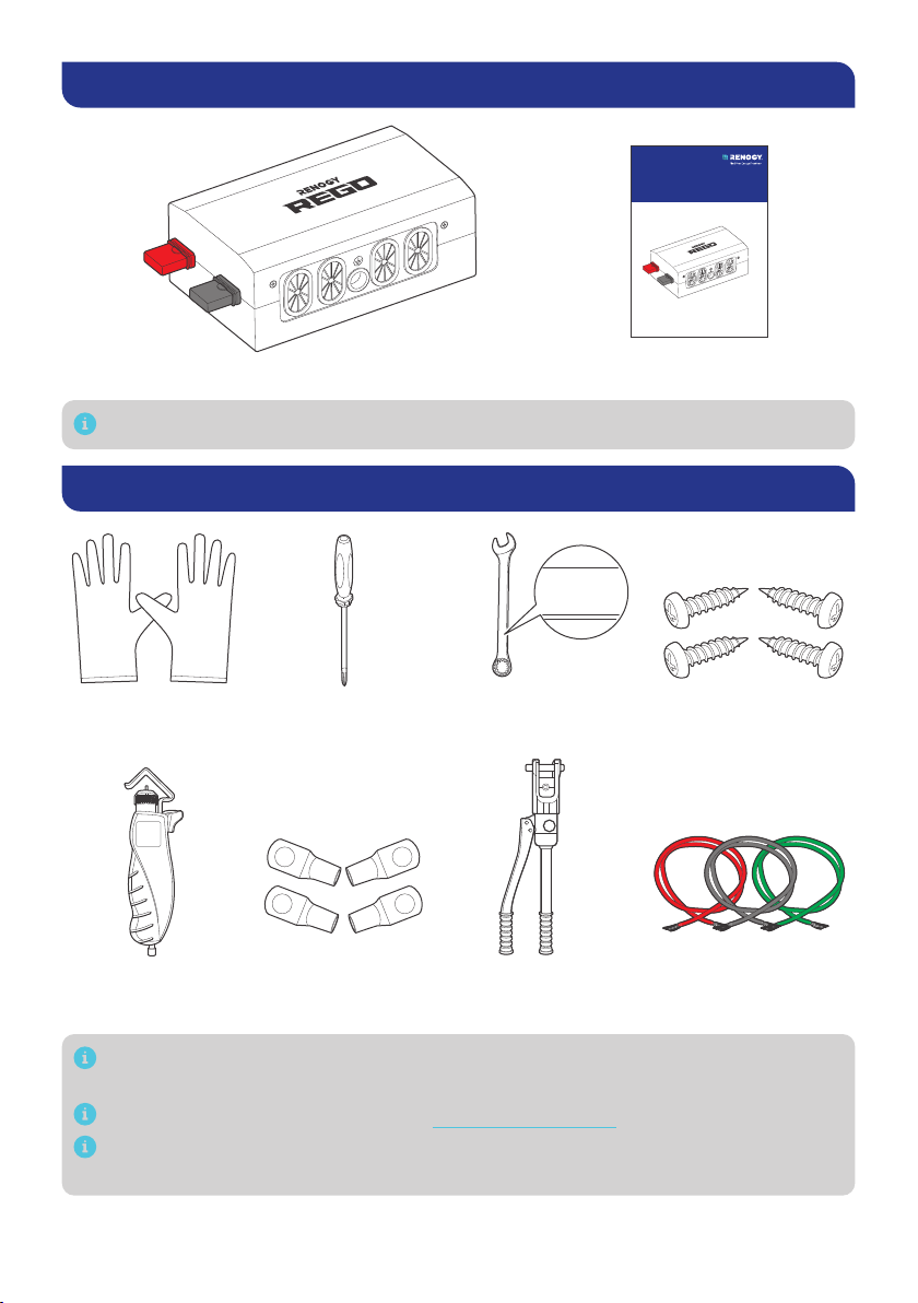
What’s In the Box?
VERSION A0
USER MANUAL
500A Combiner Box
REGO
ROA500CB-98
REGO 500A Combiner Box × 1 User Manual × 1
Make sure the combiner box is free of any signs of damage.
Required Tools & Accessories
3/8 in Lugs
(M10 Ring Terminals)
Insulating Gloves Phillips
Screwdriver (#2)
Wire Stripper Manual
Hydraulic Pliers
Bare Wires
Self-tapping
Screws x 4
ST6.3
Wrench
(17/32 in)
13mm
13mm
13mm
Prior to installing and configuring the combiner box, prepare the recommended
tools, components, and accessories.
For how to size bare wires, refer to “How to Size Cables?” in this manual.
Choose proper mounting screws specific to your installation site. This manual
takes self-tapping screws for wooden walls as an example.
— 3 —
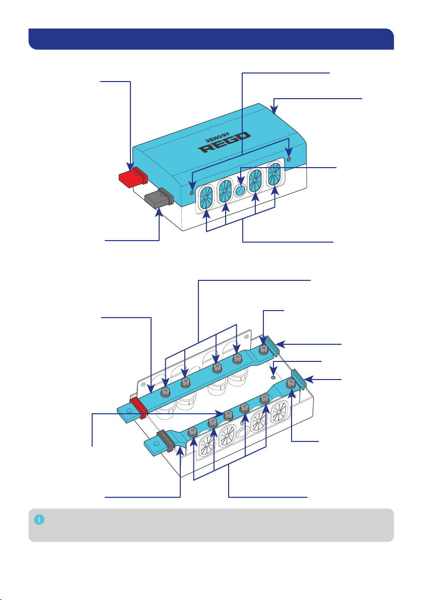
Get to Know REGO 500A Combiner Box
█Exterior
Positive Busbar
Dust Cover
Negative Busbar
Dust Cover
Ground Port
Cables Ports
Cover Screws
Cover
█Interior (with the cover removed)
Positive Terminals
Negative Terminals
Extend Negative
Terminal
Dust Cover
Mounting Holes
Positive Busbar
Negative Busbar
Ground Terminals
Dust Cover
Extend Positive Terminal
Each busbar terminal is equipped with a terminal bolt, a spring washer, and a flat
washer.
— 4 —
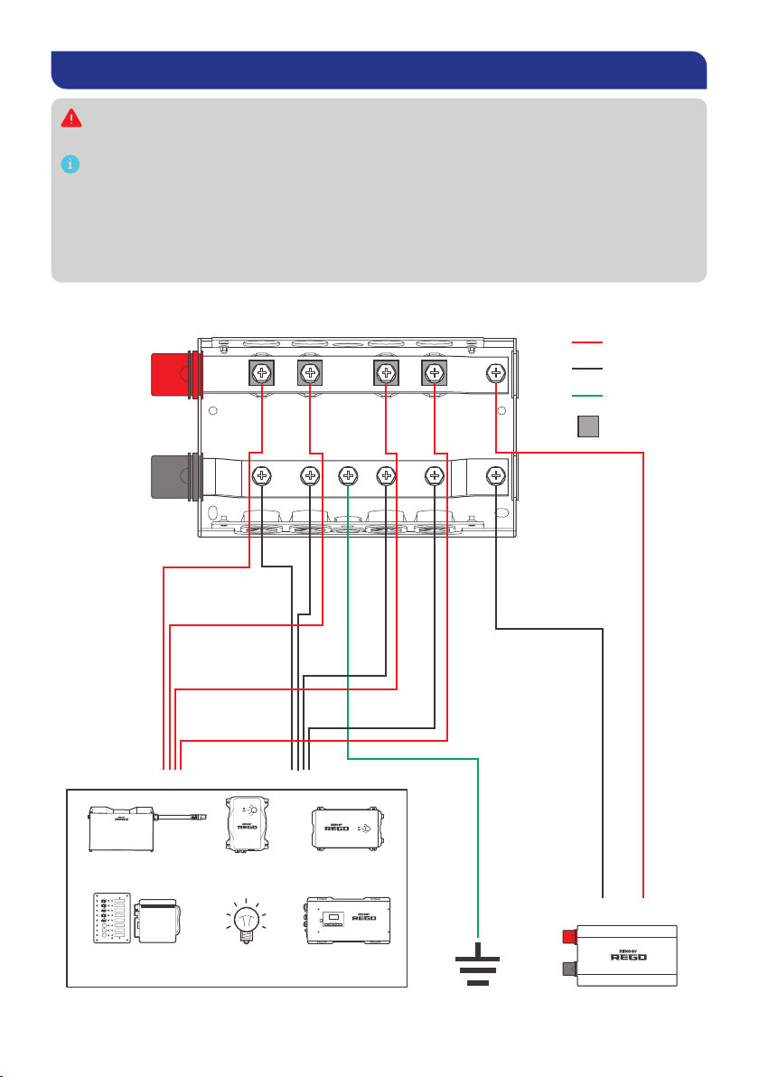
Wiring Diagram
The continuous current flowing through the combiner box shall not exceed 500A.
The voltage is within the range of 9V to 60V.
The wiring diagram only shows the key components in a typical DC-coupled
residential energy storage system for the illustrative purpose. The wiring might
be different depending on the system configuration. Additional safety devices,
including disconnect switches, emergency stops, and rapid shutdown devices,
might be required. Wire the system in accordance with the regulations at the
installation site.
Use MRBF Fuse
MRBF Fuse
Charge
Controller
Battery Battery
Charger
+
-
+
-
Positive
Negative
Ground
Inverter
Charger
Combiner BoxGroundingDevices (9V–60V, 500A Max)
DC LoadsDC Distribution
Panel or Converter
— 5 —
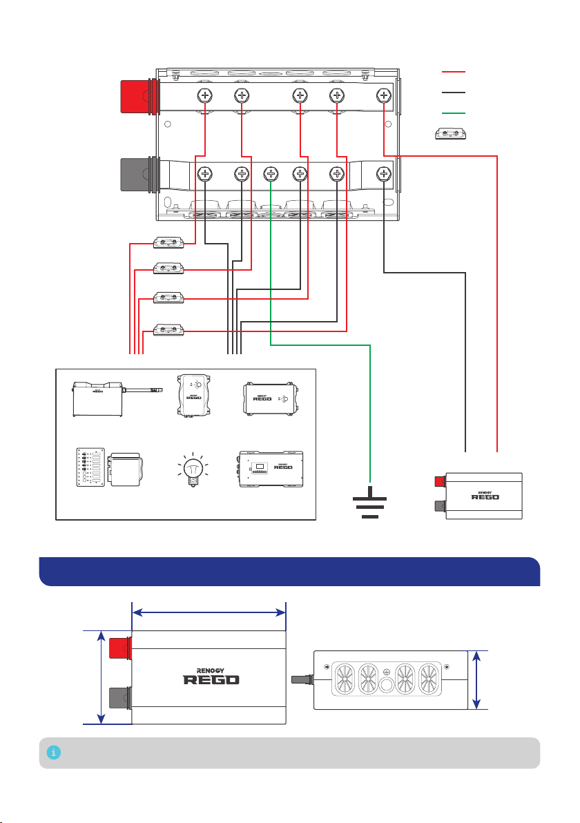
Use ANL Fuse
Charge
Controller
Battery Battery
Charger
+
-
+
-
Positive
Negative
Ground
ANL Fuse
Inverter
Charger
Combiner Box
GroundingDevices (9V–60V, 500A Max)
DC LoadsDC Distribution
Panel or Converter
Dimensions
10.35 in (263 mm)
6.30 in
(160 mm)
3.94 in
(100 mm)
Dimension tolerance: ±0.2 in (0.5 mm)
— 6 —
How to Size Cables?
Size wires specific to the operating current of relevant devices. Refer to the table below
for copper cable ampacities with different gauge sizes.
Cable Gauge Size Ampacity Cable Gauge Size Ampacity
14 AWG (2.08 mm²) 35A 2 AWG (33.6 mm²) 190A
12 AWG (3.31 mm²) 40A 1 AWG (42.4 mm²) 220A
10 AWG (5.25 mm²) 55A 1/0 AWG (53.5 mm²) 260A
8 AWG (8.36 mm²) 80A 2/0 AWG (67.4 mm²) 300A
6 AWG (13.3 mm²) 105A 4/0 AWG (107 mm²) 405A
4 AWG (21.1 mm²) 140A
The above values are from the NEC Table 310.15(B)16 for copper cables rated at
167°F (75°C), operating at an ambient temperature of no more than 86°F (30°C).
Cables longer than 6 feet (1829 mm) may require thicker gauge wires to prevent
excessive voltage drop in undersized wiring.
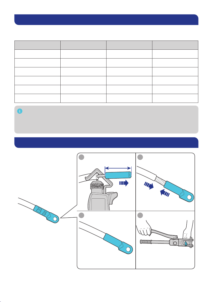
How to Install the 3/8 in Lugs (M10 Ring Terminals)?
21
43
0.4 in (10 mm)
— 7 —
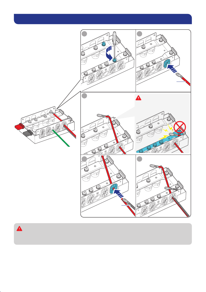
How to Connect Energy Devices to the Busbars Safely?
1
3
2
4 5
Positive
Negative
Keep a safe distance
between the positive
terminal and the
negative busbar.
Avoid contact between
the positive terminal
and the negative
busbar.
Ensure that the positive busbar terminal does not come into contact with the
negative busbar terminal. Short circuits can damage connected batteries and
devices.
Questo manuale è adatto per i seguenti modelli
1
Indice
Altri manuali Renogy Pacco batterie


