REVENT RVL50 Manuale utente

Installation Guide
Read and Save These Instructions
Watch the installation video at:
reventfans.com/install
Questions? Call
1-877-543-8698 (English) or
1-800-615-5439 (French)
models RVL50, RVL70,
RVL80, RVL90, RVL110,
RVL130, RVL150
Need Help?
English

1
Table of Contents
Please Read and Save
These Instructions
page 1
page 1-2
page 3
page 4
page 5
page 6
page 7
page 8-13
page 14-19
page 19
page 20
page 21
Table of Contents
Specifications
What’s Inside The Box
Safety Information
Planning Your Installation
Connecting The Duct
Removing Your Old Fan
SheetLock®Easy Roomside Installation
Installation For New Construction Framing
Care And Cleaning
Frequently Asked Questions
3-Year Limited Warranty
...............
...........
...............
...............
...............
...............
...............
..........
........
.............
.............
.............
Specifications
Duct Exhaust Diameter
Voltage
Frequency
Fan Watts
LED Watts
LED Brightness
LED Color Temp
Air Flow
Fan Weight
Sound
Shield Size
Housing Length*
Housing Width*
Housing Depth*
4 in ( 10.2 cm )
120 V
60 Hz
13 W, 16 W, 20 W
13 W
900, 1000, or 1000 Lumens
2700, 4000, or 5000 Kelvin
50 CFM, 70 CFM, 80 CFM
5.25 Lbs ( 2.4 Kg )
0.3 Sone, 0.7 Sone, 0.8 Sone
11 x 11 in ( 27.9 x 27.9 cm )
8 3/8in ( 21.3 cm )
7 7/8in ( 20 cm )
5 1/8in ( 13 cm )
RVL50, RVL70, RVL80
*This may require modification of your current opening. Some hand
tools required. Power tools may also be necessary.

2
RVL90, RVL110
Duct Exhaust Diameter
Voltage
Frequency
Fan Watts
LED Watts
LED Brightness
LED Color Temp
Air Flow
Fan Weight
Sound
Shield Size
Housing Length*
Housing Width*
Housing Depth*
4 in ( 10.2 cm )
120 V
60 Hz
23 W, 30 W
13 W
900, 1000, or 1000 Lumens
2700, 4000, or 5000 Kelvin
90 CFM, 110 CFM
6.95 Lbs ( 3.15 Kg )
0.7 Sone, 1.3 Sone
12 5/8x 12 5/8in ( 32.1 x 32.1 cm )
9 3/4in ( 24.8 cm )
9 1/2in ( 24.1 cm )
6 3/8in ( 16.2 cm )
*This may require modification of your current opening. Some hand
tools required. Power tools may also be necessary.
RVL130, RVL150
Duct Exhaust Diameter
Voltage
Frequency
Fan Watts
LED Watts
LED Brightness
LED Color Temp
Air Flow
Fan Weight
Sound
Shield Size
Housing Length*
Housing Width*
Housing Depth*
6 in ( 15.24 cm )
120 V
60 Hz
34 W, 40 W
13 W
900, 1000, or 1000 Lumens
2700, 4000, or 5000 Kelvin
130 CFM, 150 CFM
8.6 Lbs ( 3.9 Kg )
1 Sone, 1 Sone
13 3/8x 13 3/8in ( 34 x 34 cm )
10 1/2in ( 26.7 cm )
10 3/8in ( 26.4 cm )
7 5/8in ( 19.4 cm )
*This may require modification of your current opening. Some hand
tools required. Power tools may also be necessary.

3
What’s Inside The Box
FAN
Qty:1
DAMPER
Qty:1
SHIELD
Qty:1
SHORT BRACKET
(used for new
construction only)
Qty:2
LONG BRACKET
(used for new
construction only)
Qty:1
MANUAL
Qty:1
TEMPLATE
Qty:1
TRIM RING
Qty:1
ROUNDHEAD
WOOD
SCREW
(used for new
construction only)
Qty:6
2-WIRE QUICK
CONNECT
Qty:2
(U.S.A. only)
WIRE NUT
Qty:4
(Canada only)
4-WIRE QUICK
CONNECT
Qty:3
(U.S.A. only)
Installation Guide
Read and SaveThese Instructions
Watchthe installation video at:
reventfans.com/install
Questions?Call
1-877-543-8698(English) or
1-800-615-5439(French)
models RVL50, RVL70,
RVL80, RVL90, RVL110,
RVL130, RVL150
Need Help?
English
#8 x 3/8"
BRACKET
SECURING
SCREW
(used for new
construction only)
Qty:3

4
Safety Information
1.) WARNING - TO REDUCE THE RISK OF FIRE, ELECTRIC SHOCK,
OR INJURY TO PERSONS, OBSERVE THE FOLLOWING:
a) Installation work and electrical wiring must be done by qualified person(s) in
accordance with all applicable codes and standards, including fire-rated
construction.
b) Sufficient air is needed for proper combustion and exhausting of gases
through the flue (chimney) of fuel burning equipment to prevent back drafting.
Follow the heating equipment manufacturer's guideline and safety standards,
such as those published by the National Fire Protection Association (NFPA), the
American Society for Heating, Refrigeration and Air Conditioning Engineers
(ASHRAE), and the local code authorities.
c) When cutting or drilling into wall or ceiling, do not damage electrical wiring and
other hidden utilities.
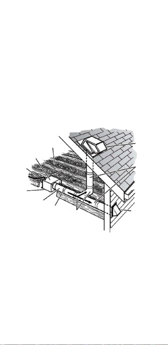
d) Ducted fans must always be vented to the outdoors.
e) If this unit is to be installed over a tub or shower, it must be marked as
appropriate for the application and be connected to a GFCI (Ground Fault Circuit
Interrupter) - protected branch circuit.
2.) Use this unit only in the manner intended by the manufacturer. If you have
questions, contact the manufacturer.
3.) Before servicing or cleaning unit, switch power off at service panel and lock the
service disconnecting means to prevent power from being switched on accidentally.
When the service disconnecting means cannot be locked, securely fasten a
prominent warning device, such as a tag, to the service panel.
4.) This ventilation fan is approved for use over a bathtub or shower when installed
in a GFCI protected circuit. Do not use unapproved fans over a bathtub or shower
that are not approved for that application.
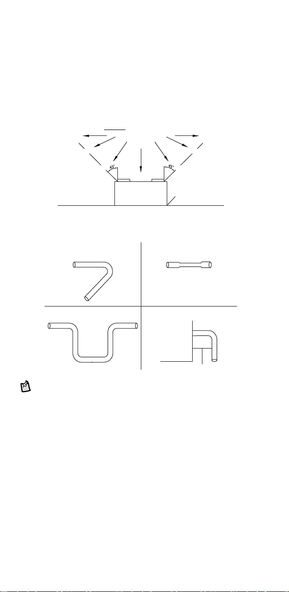
5.) Install ductwork in a straight line with minimal bends.
6.) Use 120 V, 60 Hz for the electrical supply and properly ground the unit. Follow
all local safety and electrical codes.
7.) Do not use this fan with any solid-state control device; such as a dimmer switch.
Solid-state controls may cause harmonic distortion, which can cause a motor
humming noise, as well as increase risk of fire or electric shock.
8.) To reduce the risk of fire or electric shock, do not block air entry shield.
9.) Mount with the lowest moving parts at least 8.2 ft (2.5 m) above floor or grade
level.
10.) Never place a switch where it can be reached from a tub or shower.
11.) Not to be installed in a ceiling thermally insulated to a value greater than R50.
(This is required for installation in Canada only).
12.) Not for use in cooking areas. (See PAGE 5 for details)
13.) This product must properly connect to the grounding conductor of the supply
circuit.
Follow the heating equipment manufacturer’s guideline and safety standards, such
as those published by the National Fire Protection Association (NFPA), the
American Society for Heating, Refrigeration and Air Conditioning Engineers
(ASHRAE), and the local code authorities.
WARNING: Not suitable for use as a range hood.
CAUTION: For General Ventilating Use Only - Do Not Use To Exhaust
Hazardous Or Explosive Materials And Vapors.
CAUTION: Do not install in locations where the temperature will exceed
104°F (40°C).
IMPORTANT: Exercise care to not damage existing wiring when cutting or
drilling into walls or ceilings.
NOTE: Make sure duct work size is a minimum of the discharge. Do not
reduce. Reducing the duct size can increase fan noise.
IMPORTANT: You may want to consult with a qualified licensed electrician
regarding the wiring of your ventilation fan.
WARNING: To reduce the risk of electric shock, please disconnect the
electrical supply circuit before servicing.
CAUTION: This product must be properly grounded.
Go to reventfans.com to obtain a copy of this manual.

5
NOTE: If installing in existing construction, you may need to have access to
space above and below the installation location.
Cooking Area
do not install above or
inside this area
Cooking
Equipment Floor
Turning angle too sharp
Too many elbows
Avoid duct shrink
Elbow near the body
Fan
Body
Minimum 18 in ( 45.72 cm )
Planning Your Installation
When installing the ventilation fan in a new construction site, install the main body
of the FAN and duct work during the rough-in construction of the building. The
SHIELD should be installed after the finished ceiling is in place.
When installing in existing construction, use the provided cutout TEMPLATE for the
ceiling. SHIELD edge should overlap finished ceiling.
Not for use in cooking area - see diagram below.
Do not install ventilation fan in areas where the duct work will require configuration
as shown.
There are multiple installation configurations possible for this ventilation fan. Not all
configurations are shown. If your installation requires a variation other than those
shown, consult with a licensed contractor to determine the best installation for your
project. If you are replacing an existing fan, ensure that the new FAN will
adequately cover the existing opening.

Connecting the Duct
●Install a circular duct to outlet and secure it with duct tape or clamps.
●Install the duct to the outlet with a gradient 1°~2° to the outside as shown.
●The ducting from this FAN to the outside of the building has a strong effect on
●the air flow, noise and energy use of the fan. Use the shortest, straightest duct
●routing possible for best performance, and avoid installing the FAN with smaller
●ducts than recommended. Insulation around the ducts can reduce energy loss
●and inhibit mold growth. Fans installed with existing ducts may not achieve their
●rated airflow.
●For models RVL50, RVL70, RVL80, RVL90, or RVL110, 4 in (10.16 cm) round is
●recommended for best performance. For models RVL130 or RVL150,
●6 in (15.24 cm) round is recommended for best performance.
●Ensure duct joints and exterior penetrations are sealed with caulk or other
●similar material to create an air-tight path, to minimize building heat loss and
●gain, and to reduce the potential for condensation.
●Place/wrap insulation around duct and/or FAN in order to minimize possible
●condensation buildup within the duct, building heat loss and gain.
6
INSULATION*
(Place around and
over Fan Housing.)
Seal gaps
around
housing.
ROUND
DUCT*
POWER
CABLE*
Seal duct
joints with
tape.
FAN
HOUSING
ROUND
ELBOWS*
ROOF CAP*
(with built-in
damper)
Keep duct
runs short.
WALL CAP*
(with built-in
damper)
*Purchase
separately.
OR

7
Removing Your Old Fan
1.) Disconnect the electrical power supply and lock out the service
panel for the existing fan.
2.) Remove the grille from the existing fan. Pull the grille down to expose it’s two
springs. Squeeze each spring together and pull down again to release the springs
from the motor plate slots.
3.) Your existing fan may be attached in several ways. Look for attachment screws
in the ceiling and remove. Your fan may also be attached on the attic side, which
will require you to access it from the attic. Locate attic attachment screws and
remove.
4.) Remove the old fan. This may require cutting and pulling. Wear gloves and
eye protection.

8
1.) Place the provided sheetrock cutout TEMPLATE on ceiling where you wish the
FAN to be (DAMPER and electrical positions shown on TEMPLATE). We suggest
using painter’s masking tape to hold the template in place while cutting. If there is a
pre-existing fan opening, use aligning windows to find it’s edges. Either cut through
the provided guide slots in the TEMPLATE, or mark your cut lines with a pencil and
remove the TEMPLATE. Use a sheetrock jab saw to cut your fan opening in the
ceiling.
SheetLock®Easy Roomside
Installation
Watch the video: REVENTFANS.COM/INSTALL
WARNING: Disconnect all AC Power Breakers or Fuses before attempting
to cut into your ceiling.
2.) Use a flathead screwdriver to raise the DAMPER away from the notch in the
FAN body, then slide the DAMPER up half way until the notch in the side of the
DAMPER aligns with the upper set of guides. Remove the DAMPER from the FAN.
Remove
DAMPER
from FAN
at notch
flathead
screwdriver
FAN
DAMPER
notch
guide
TEMPLATE
sheetrock jab saw
guide

9
4.) Attach conduit with wiring to FAN.
conduit
FAN
6.) Select a set of holding tabs, depending on the thickness of your sheetrock.
5/8in (1.6 cm)
holding tab
1/2in (1.3 cm)
holding tab
final securing tab 5/8in (1.6 cm)
holding tab
1/2in (1.3 cm)
holding tab
5.) Reattach DAMPER to FAN inside the ceiling, damper should click into place
securely.
ducting
conduit
DAMPER
FAN
3.) Attach DAMPER to ducting. Tape DAMPER to ducting with duct tape. Set the
connected DAMPER and ducting in the ceiling opening, then set the FAN in the
ceiling opening as well.
ceiling
ducting
Connect DAMPER and
ducting with duct tape
Place FAN and DAMPER
inside CEILING opening
ceiling
ceiling
FAN
DAMPER
Altri manuali per RVL50
1
Questo manuale è adatto per i seguenti modelli
8
Indice
Altri manuali REVENT Fan

REVENT
REVENT RVSH130 Manuale utente

REVENT
REVENT RVLH80 Manuale utente

REVENT
REVENT RVS50 Manuale utente

REVENT
REVENT RVP50 Manuale utente

REVENT
REVENT RVSH50 Manuale utente

REVENT
REVENT RVLH50 Manuale utente

REVENT
REVENT RVL50 Manuale utente

REVENT
REVENT RVS50 Manuale utente

REVENT
REVENT RVM80 Manuale utente

REVENT
REVENT RVSH50 Manuale utente


