REXON PJ2+ Manuale utente

2
Important Notice
FCC RF Exposure Compliance Requirements
for Occupational Use Only
This radio has been tested and complies with the Federal
Communications Commission (FCC) RF exposure limits for
Occupational Use/Controlled Exposure Environment. In addition,
it complies with the following Standards and Guidelines:
• FCC 96-926, Guidelines for Evaluating the Environmental Effects of
Radio-Frequency Radiation.
• FCC OET Bulletin 65 Edition 97-01 (1997) Supplement C, Evaluating
Compliance with FCC Guidelines for Human Exposure to Radio
Frequency Electromagnetic Fields.
• ANSI/IEEE C95.1-1992, IEEE Standard for Safety Levels with Respect
to Human Exposure to Radio Frequency Electromagnetic Fields,
3 kHz to 300 GHz.
• ANSI/IEEE C95.3-1992, IEEE Recommended Practice for the
Measurement of Potentially Hazardous Electromagnetic Fields -
RF and Microwave.
• When transmitting, hold the radio in a vertical position with its
microphone 1 to 2 inches (2.5 to 5 cm) away from your mouth
and keep the antenna at least 1 inch (2.5 cm) away from your
head and body.
• The radio must be used with a maximum operating duty cycle
not exceeding 50%, in typical Push-to-Talk configurations.
DO NOT transmit for more than 50% of total radio use time
(50% duty cycle). Transmitting more than 50% of the time can
cause FCC RF exposure compliance requirements to be exceeded.
The radio is transmitting when TX is on the front panel of the radio
is illuminated. You can cause the radio to transmit by pressing the
P-T-T button.
• Always use Sporty’s authorized accessories.
Manual_final.indd 2 7/13/22 1:51 PM

3
Simplified Directions
1. Install the batteries.
2. Turn the unit on
(rotate volume knob clockwise).
3. Enter the desired frequency
(1 2 2 9 7 5 for 122.975 MHz).
Note: Six digits may be required to select
certain frequencies.
4. Listen and transmit.
Manual_final.indd 3 7/13/22 1:51 PM

4
Table of Contents
General Information
Introduction 5
Features 5
Warranty 6
Antenna Requirements 6
Batteries 7
External Power 8
Precautions 9
Controls
Top View 10
Left Side View 10
Right Side View 10
Front View 12
Back View 12
Operating Instructions
Manual Frequency Selection 14
Frequency Search 15
Frequency Memory 16
Memory Recall 18
Memory Scan 19
Memory Clear 20
Transmitting 21
Using a Headset 22
Automatic Noise Limiting 23
Key Lock 24
Screen and Keypad Lighting 24
NOAA Weather Band 25
Emergency Frequency Selection 26
Low Back Light Mode 26
High Back Light Mode 26
LCD Contrast Adjustment 26
Night Mode 27
Specifications 28
Manual_final.indd 4 7/13/22 1:51 PM

5
General Information
Introduction
This manual contains only operational information relative to the
PJ2+ COM radio. This manual is not intended as a service or maintenance
manual and does not contain any theory or schematic diagrams.
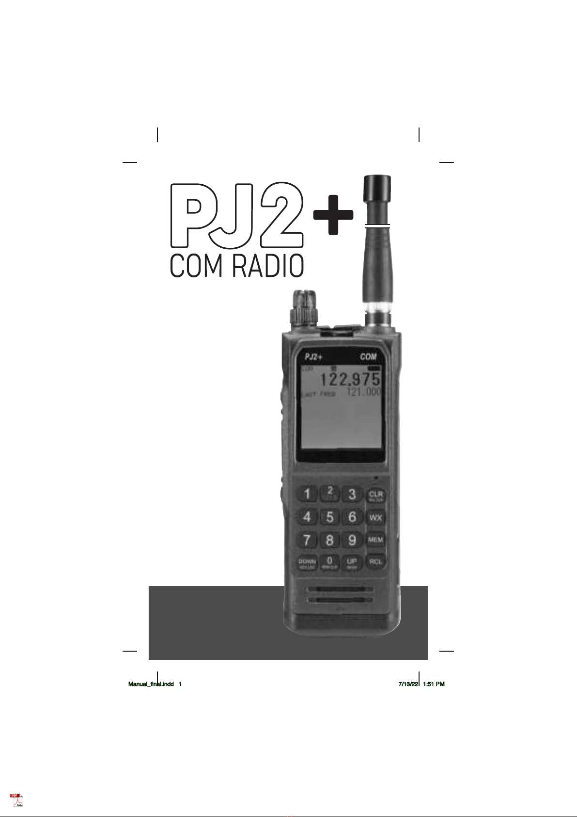
Features
Rexon PJ2+ COM is a hand-held, aircraft communication transceiver with
the following features:
• Standard twin plug aviation headset jacks
• 3.5mm earbud/headset jack
• Accepts USB type C power (2.4 amps)
• 760 COMM frequencies (118.000 MHz to 136.975 MHz)
• 6 watts (PEP) transmit power while on batteries
• Auto-Lit keypad and screen
• 20 Visual memory channels
• Automatic noise limiting (ANL)
• Full feature scanner—Scan the 20 memory channels or the entire
frequency range
• Key lock
• Large 1.5" x 1.63" LCD screen
• Low battery indicator
• NOAA weather band
• External power and antenna options
• 121.5 emergency frequency button
• Last frequency function with visible last frequency
• Side-tone
• Adjustable LCD screen
• Night mode
• Easy to use
Manual_final.indd 5 7/13/22 1:51 PM

6
Warranty
If, during the first year, your PJ2+ COM transceiver fails due to defective
workmanship or parts under normal use, we will replace it or repair it at
our option.
The warranty does not apply to units subject to misuse, battery leakage,
neglect or accidents. Nor does the warranty apply to units damaged by
lightning, excess current, moisture, units repaired or altered outside the
factory, units with altered or removed serial numbers, or units used with
accessories other than those approved by the factory.
To have your unit serviced under this warranty, return it postage paid
with proof of purchase to:
Sporty’s Pilot Shop
Clermont County/Sporty’s Airport
2001 Sportys Drive
Batavia, Ohio 45103-9719
If your PJ2+ COM is no longer under warranty, you may still have it
serviced at Sporty’s. See above for return address instructions.
Antenna Requirements
Included with the PJ2+ COM is a flexible rubber antenna (Rubber Duck).
However, an external antenna may be needed if operating inside an
aircraft (must be properly installed by an aircraft radio shop), automobile
or other metal enclosure.
On top of the PJ2+ COM is a BNC connector, which is standard for use
on aircraft radios. Therefore, little difficulty should be encountered in
connecting an existing aircraft radio antenna to the PJ2+ COM.
Manual_final.indd 6 7/13/22 1:51 PM
7
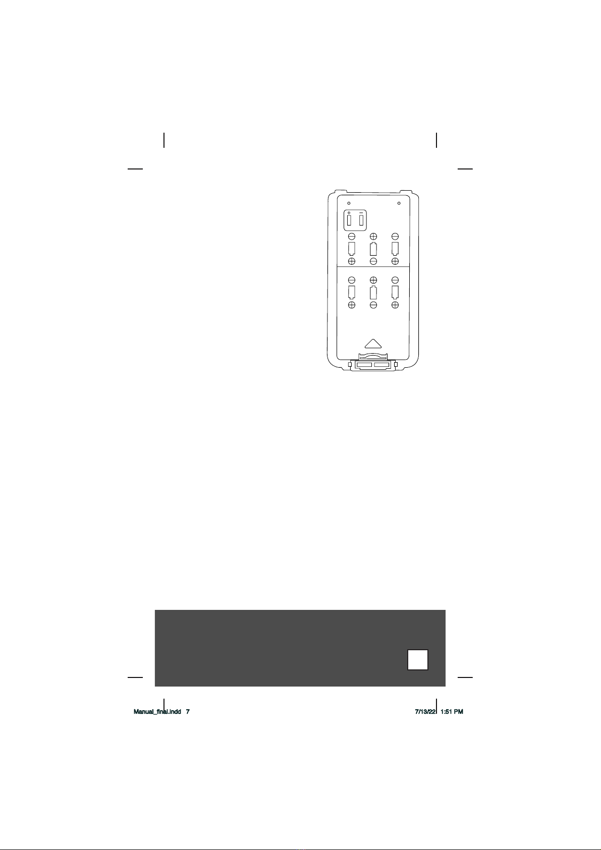
Batteries
An Alkaline Battery Pack is standard
equipment with the PJ2+ COM. Alkaline
batteries are a good power source for a
backup radio because they have excellent
storage life and no maintenance is
required. The Alkaline Battery Pack is
NOT rechargeable. The batteries must be
replaced. To replace the batteries, turn the
power OFF and then remove the battery
pack from the unit by holding the belt
clip (if installed) in the out position, and
then lift the latch mechanism found at
the bottom of the battery pack. Remove
the battery cover by pulling the thumb
latch in the direction of the arrow. Six 1.5
volt AA Alkaline batteries are required.
Energizer batteries are the recommended
battery for the PJ2+ COM. Results may
vary when using off brand batteries.
Replace the batteries by following the positive (+) and negative (-)
terminal markings inside the case. When the batteries are replaced,
replace the battery cover and attach the battery pack to the radio.
To attach the battery pack, make sure the power is OFF. Slide the
battery pack onto the back of the and push in on the bottom until it
locks in place.
If the radio will not be used for a long period of time (six months or
more), please remove the batteries from the battery pack. This will help
prevent the batteries from corroding the battery pack.
Manual_final.indd 7 7/13/22 1:51 PM
8
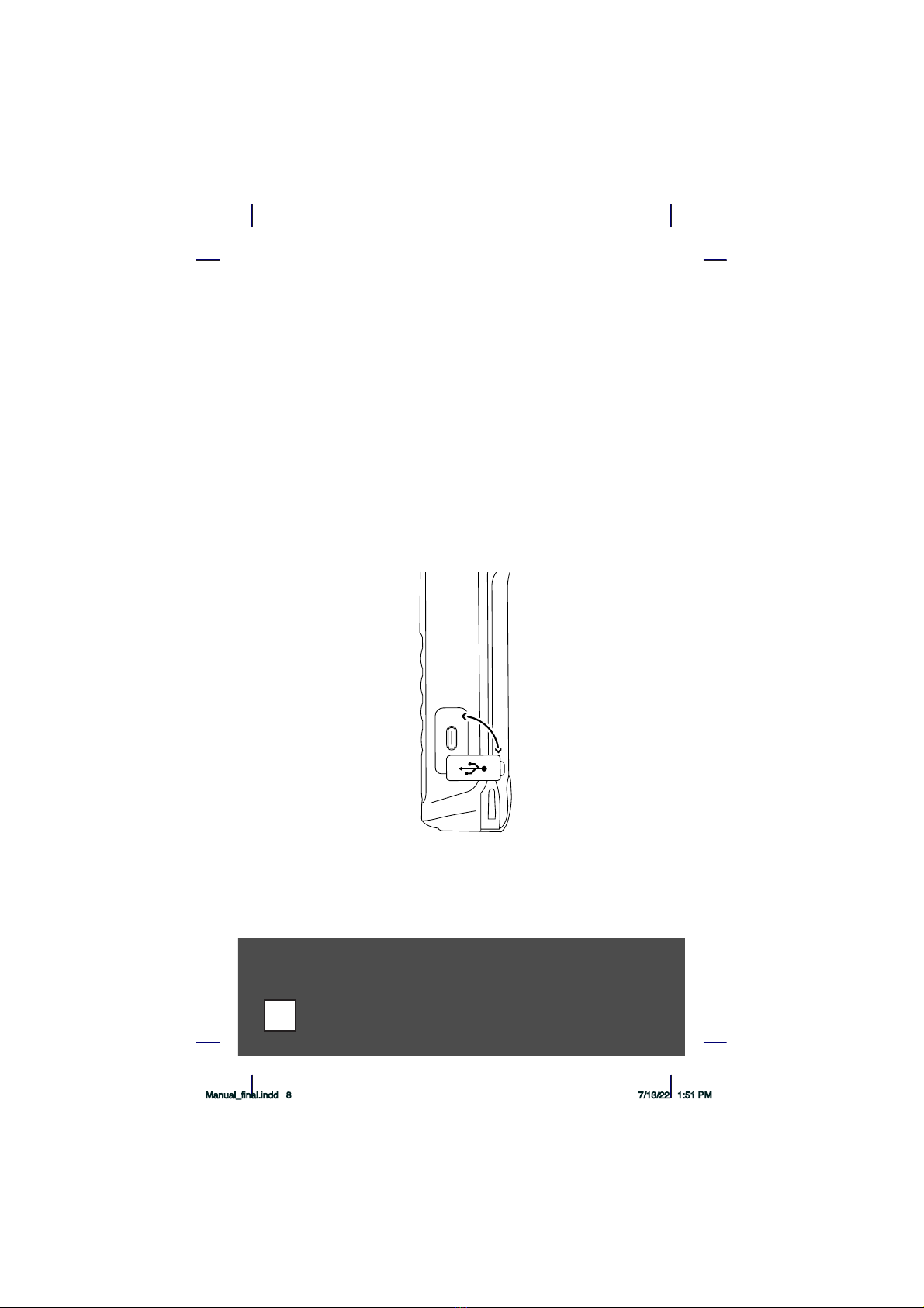
External Power
The PJ2+ COM includes a wall adapter and USB-A to USB-C power cable.
The wall adapter can be used in 100-240 volt applications. The USB-A port
on the wall adapter provides the needed 2.4 amps to properly power the
PJ2+ COM. If less than 2.4 amps is provided, the PJ2+ COM will receive
transmissions, but it won’t have enough power to transmit. If attempting
to transmit on less than 2.4 amps, the PJ2+ COM screen will flash
intermittently and beep. To remedy this issue, change the power source to
provide the needed 2.4 amps, or use the alkaline battery pack.
The PJ2+ COM does not have power delivery capability. Power should
only be provided from a USB-A port.
Another option for external power is to use a backup tablet battery pack
(sold separately). Be sure to use a battery pack that provides at least
2.4 amps of power.
Note: When powering the PJ2+ COM through the Type-C power port on
the side of the radio, the radio will transmit at 5 Watts (PEP).
Manual_final.indd 8 7/13/22 1:51 PM

9
Precautions:
• Changes or modifications not expressly approved by the
manufacturer for compliance could void the user’s authority to
operate the equipment.
• Never attempt to service this unit yourself. It should be referred
to qualified service personnel. Please read the Warranty section in
this manual.
• If liquid spills or some solid object falls into the unit, remove the
battery pack or external power adapter and have the unit checked by
a qualified person before further operation.
• Never dispose of batteries or battery packs in a fire.
They may explode.
• Never leave weak or dead batteries in the Alkaline Battery Pack.
They may leak and cause permanent damage.
• Never store a battery pack where it may be accidentally shorted.
• Use only the approved external power adapters and battery packs.
• Never touch an external antenna when the danger of lightning
is present.
• Do not leave the transceiver near heat sources, such as radiators or
air ducts, or place the transceiver in an environment where the
radio will be subjected to moisture, excessive dust, shock or
mechanical vibration.
• Abrasive cleaners or chemical solvents may mar or damage the
case. Clean the transceiver with a soft cloth dampened with a mild
detergent solution.
• If operating the transceiver at temperatures outside the range of
-20°F to 122°F (-30°C to 50°C), the LCD (screen) may not display
the selected frequency. If the PJ2+ COM is used in temperatures
lower than the recommended range, the characters being displayed
may change very slowly. These irregularities will disappear, with
no harm to the PJ2+ COM, when operation is resumed within the
recommended temperature range.
Manual_final.indd 9 7/13/22 1:51 PM

Controls
This section serves only to identify and briefly describe the PJ2+ COM’s
external features. Please see the Operating Instructions section for detailed
instructions on the use of the PJ2+ COM.
Top View
(A) Antenna Connector
The flexible rubber antenna or an external antenna may be attached
to this BNC connector.
(B) 3.5mm Jack
An ear bud or compatible headset can be plugged in here. The
internal microphone + speaker are disabled when the jack is used.
(C) Squelch
Rotate clockwise to increase squelch and counterclockwise to
decrease squelch.
(D) On/Off and Volume Control
Combination on/off and volume control. Turn the knob clockwise
from the OFF position to turn the unit on and to increase volume.
Turn the knob counterclockwise to decrease volume and to turn the
unit off.
(E) Earphone Jack
A standard headphone PJ plug will fit into here. The internal speaker
is disabled when this jack is used.
(F) Microphone Jack
A standard microphone PJ plug will fit into here. The internal
microphone is disabled when this jack is used.
(G) Wrist Strap Attachment point
A wrist strap can attach to this location.
Left Side View
(H) Push-To-Talk Button
This button activates the internal microphone or an external
microphone when using the optional headset adapter.
(H) Light Button
This button activates the back lighting for the screen and keypad.
This key is also used in combination with the Clear key to enable/
disable the auto-light feature.
(J) Flip/Flop Button
This switch is used to flip flop between your current and last frequency.
Right Side View
(K) External USB-C Power Port
The PJ2+ COM may be powered externally, with or without a battery
pack attached by plugging a 100 - 220 Volt Wall Power Adapter into
this location. Note that the PJ2+ COM needs 2.4 amps to operate
properly. Wall adapters providing less amps should not be used.
Use the wall plug that was included in the box.
Manual_final.indd 10 7/13/22 1:51 PM
Indice
Altri manuali REXON Radio


