Rietschle Thomas 2660CE37-807 Guida rapida

2660CE37-807&2660CGHI42-807
Compressor
Field Service Manual
©2003 Thomas Industries Sheboygan, Inc.
FSM 0159 Rev. A 07/04
A Thomas Industries Company

2

3
A Field Service Manual
Prepared by
Thomas Compressor
2660CE37-807 & 2660CGHI42-807
Field Service Manual
©2003 Thomas Industries, Sheboygan Inc. Field Service Manual FSM 0159
Rev. A 0704
Table of Contents
Page
Introduction ..................................................................................................................................................................... 4
Safety First ....................................................................................................................................................................... 5
Exploded View and Parts List..................................................................................................................................... 6 - 7
Preventive Maintenance and Troubleshooting Guide.................................................................................................9 - 10
Required Tools and Materials ........................................................................................................................................ 11
ComponentRepair ......................................................................................................................................................... 11
Servicing the Head or Valve Assembly.................................................................................................................... 11
Servicing the Connecting Rod Assembly and Eccentric Assembly ....................................................................... 16
Reassembling the Compressor ................................................................................................................................ 20
A Thomas Industries Company

4
Introduction
This Field Service Manual is intended for use ONLY by properly trained and experienced repair personnel employed by an
authorizedservice center. THISSERVICE MANUALSHOULD NOTBE USED BY OR DISTRIBUTED TO THE PUBLIC.
THE INSTRUCTIONS AND WARNINGS HEREIN PRESUME EXISTING FAMILIARITY WITH THE DESIGN AND
FUNCTION OF THESE AND SIMILAR PRODUCTS, AND THEIR COMPONENTS.
Please Note:
Themodel(s)representedinthismanualmayhaveadditionsand/ormodificationsmadeatanytime. Picturesrepresentastandard
unit series and an actual unit may vary slightly. This manual is based on the latest technical information available at the time of
creationorlastrevision. Itisbelievedtobegenerallyaccurateandreliable. Consultthefactoryifadditionaldetailedinformation
is desired, or whenever there is a question about a given unit’s configuration or performance specifications.

5
Safety First
It is recommended that you thoroughly read and understand this manual before you attempt to service the
Thomas series of compressors to which this applies. PLEASENOTETHEFOLLOWINGCAUTIONS
AND WARNINGS FOR YOUR OWN SAFETY.
Caution
Toavoidpersonalinjuryand/or property damage, only authorized servicepersonnelshould
service this unit.
Warning
Toavoidtheriskofelectricalshock,personalinjury,ordeath,disconnectpowerbeforeservicingthis
unit.
Caution
To avoid personal injury, do not remove fan guards while unit is connected to power.
Caution
To avoid personal injury, especially to eyes and face, use eye and face protection when
servicing this unit.
Caution
To avoid personal injury, especially to eyes and face, never point the exhaust air flow at
yourself or other people in the area. Unit is capable of pressures of 100 psig.
Caution
Toavoiddamage,neverlubricateany component in your compressor. All moving parts are
permanently lubricated.
Caution
Toavoidpropertydamage or personal injury,alwaystryrotatingthe fan by HAND priorto
connectingtheunittothepowersource. Checkforsuctionattheairinletportbyplacingyour
finger over the port as you turn the fan. You should feel a slight suction with each rotation
ofthefan. Ifyoudontfeelsuction,orifyoufeelorhearathumpasyouturnthefan,DONOT
CONNECT THE UNIT TO A POWER SOURCE. Review the assembly procedure for
possible error.

6
Exploded View and Parts List
Exploded View of the Thomas 2660CE37-807 & 2660CGHI42-807 Series Compressor

7
Field Service Parts List for Thomas 2660CE37-807 & 2660CGHI42-807 Compressor
Item Part Qty. Qty.
No. No. Per Ass'y Per Unit Description
1 SeeChart -- 2
ConnectingRod,Eccentric&BearingAssembly
2 624677 1 2 PistonCup
3 625776 1 2 Screw-Piston CupRetainer
4 626392 1 2 PistonCupRetainer
5 618114 1 2 CylinderSleeve
6 610880 -- 1 Head
7 623143 -- 2 O-Ring-HeadGasket
8 625175 -- 8 Screw-Head
9 621591 -- 2 ValvePlate Assembly
10 617177 1 2 ValveRestraint
11 617562 2 4 ValveKeeperStrip
12 621485 2 4 ValveFlapper -Intake &Exhaust
13 621461 1 2 ValvePlate
14 625094 2 4 Screw-ValveFlapper
15 623137 -- 2 O-RingValvePlate
16 638282 -- 1 Fan - Black
17 638281 -- 1 Fan - Gray
18 638702 -- 1 PressureReliefValve
Connecting Rod, Eccentric & Bearing Assembly Chart
1 666660 -- 2 For2660CE37-807
1 666702 -- 2 For2660CGHI42-807

8
Thomas Industries recommends that you perform the following service to minimize unexpected downtime
for your compressor:
••
••
•Replace the connecting rods or piston cups and sleeves
••
••
•Replace the flapper valves
••
••
•Replace the head gasket O-rings
••
••
•Replace the valve plate O-rings
Preventive Maintenance and Troubleshooting Guide

9
If you are having a problem with your compressor, use this table to help determine the cause(s):
Problem Possible Cause Corrective Action
Low Low Unit Will Motor Loud
Flow Pressure Not Start Overheats Unit
x High voltage at Reduce voltage
compressor
x x x x Low voltage at Increase voltage
compressor
x x x Damaged valves Replace flapper valves
x x x Debris in valves Remove debris and check
for valve damage
x x x Damaged gaskets Replace gaskets
x x x Worn Cup Replace connecting rod
assembly or cup
x x x Loose head screws Tighten head screws
x Broken fan Replace fan
x x x Bent motor shaft Replace entire unit
x x Damaged capacitor Replace capacitor
x Loose fittings Tighten fittings
x x Insufficient Increase air
ventilation circulation
in enclosure to enclosure
x x Worn bearings Replace Conn Rod
Eccentric and
Bearing assembly
1
1Thermal protector in motor will interrupt current when motor overheats.
Troubleshooting Guide
10
Required Tools and Materials
To disassemble and reassemble your compressor, you need the following tools and materials:
Torque wrench that has an inch-pound scale (for head screws, set screws, flapper valve screw, and pipe plugs).
Torx®T-25 driver (for head screws).
1/8" Allen wrench attachment for torque wrench (for eccentric set screw).
1/2" Hex Socket attachment for torque wrench (for flapper valve screw).
Torx®T-27 driver (for retainer screws).
Soft, clean cloths
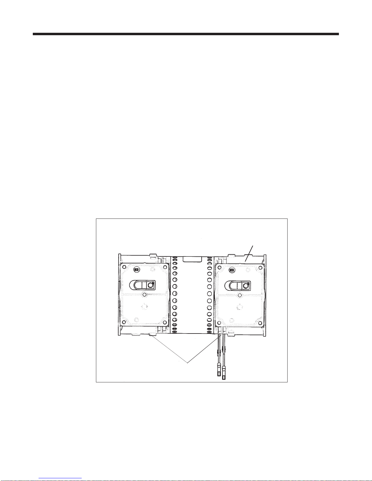
Compressor
Housing
CapacitorLEADEND
Reference Drawing: Terminology to assist with the following instructions.
CapacitorLEADSIDE
ofCompressor
Questo manuale è adatto per i seguenti modelli
1
Indice
Altri manuali Rietschle Thomas compressore d'aria


