RigExpert Tokenblauser Manuale utente
RigExpert®
Tokenblauser
User's manual
Low-noise GPSDO,
quad clock source –
0.16 to 200 MHz


Tokenblauser – a versatile GPSDO platform.......................................................4
High stability and low noise...............................................................................6
The first use......................................................................................................7
Menu description...............................................................................................8
Serial port interface..........................................................................................12
Arduino serial plotter.........................................................................................13
TimeLab interfacing...........................................................................................13
Updating the firmware.......................................................................................16
Compiling the firmware from the source code....................................................17
SI5338 configuration presets............................................................................17
Annex 1 – Specifications...................................................................................18
Annex 2 – Glossary...........................................................................................19
Table of contents

44 User's manual
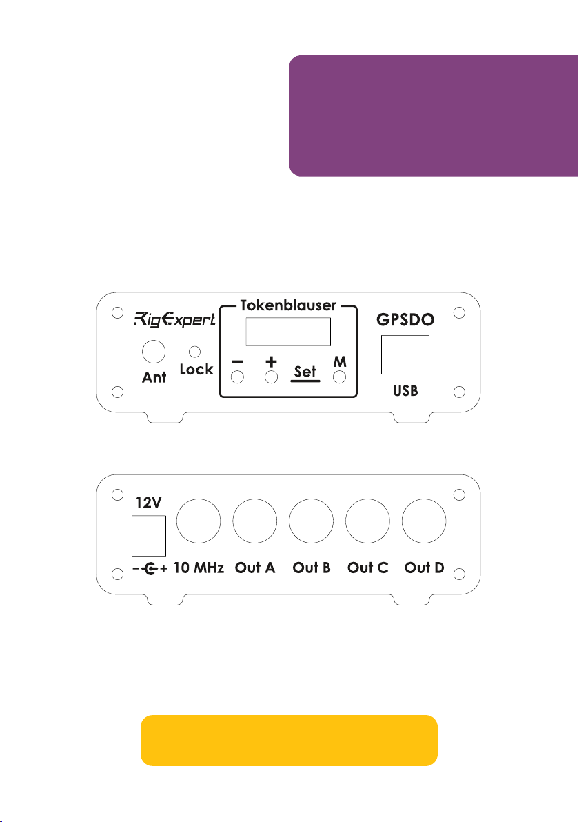
The Tokenblauser is a GPS disciplined clock source with very low noise output,
suitable for QO-100 and SHF applications, including operating FT8 and other
narrow band digital modes. Unlike many other GPSDOs with fixed 10 MHz output,
it additionally generates up to four arbitrary frequencies simultaneously. This
functionality is provided “out of the box” and does now require advanced skills
from the user. Just apply power to the device and connect a GPS antenna, then
enter or change output frequencies.
Tokenblauser –
a versatile GPSDO
platform
Example of use for operating the QO-100 satellite

Tokenblauser 5
However, we designed the Tokenblauser to be also a versatile platform for
experimenters. The device is Arduino-compatible, and the firmware is open-source.
With no or minimal changes in the code or in the hardware, an advanced user may:
• Connect the GPSDO to a computer for debug purposes or data processing
(such as plotting ADEV/MDEV graphs);
• Modify the firmware to experiment with different PLL and FLL algorithms;
• Use own GPS modules and GPS antennas;
• Use different types of OCXOs and Rubidium oscillators.
Structure diagram of the Tokenblauser GPSDO
The Tokenblauser is based on ideas of Brooks Shera, Lars Walenius and many
other enthusiasts.
66 User's manual
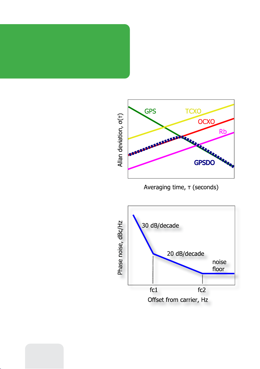
Just look at a simplified Allan
deviation chart, which compares the
stability of different types of
generators over time. The GPS receiver
itself has a bad short-term stability,
where the OCXO is good. In opposite, during long periods, the GPS is a winner.
The next chart is one of
standard models of an
oscillator phase noise.
Obviously, for a better GPSDO,
the corner frequencies fc1 and
fc2 need to be located as close to
the carrier frequency as possible.
If the GPSDO output is
multiplied by the PLL-based
oscillator, we usually think of 20
High stability
and low noise
By locking the frequency of a
local oscillator to the reference
GPS receiver, GPSDOs are
capable to have good stability
in both short-term and long-
term areas. The position of the
intersection point depends on the
type and the quality of oscillator
used; for OCXOs, it is usually 100
to 1000 seconds. Thus, OCXO-
based GPSDOs are able to provide
good frequency stability for
laboratory and hobby use.
dB/decade as a noise increment. However, this is not an axiom: much more noise
is added for frequencies to the left of fc1. By using a professional-grade OCXO, as
well as carefully designing the RF circuits, very good noise parameters of the
GPSDO can be achieved.

Tokenblauser 7
Connect the GPS antenna and
locate it in such a way, that at least ½
of the sky is visible. It is always better
to locate the antenna outdoors,
whenever possible.
Connect it to 9-15V power supply.
Once the power is turned on, the red
LED on the front panel starts flashing: the GPS module is now searching for the
satellites to synchronize time.
The first use
Once the satellites are discovered, the GPSDO starts the locking process. The
green LED is now flashing. Be patient, this may take several minutes.
Once the output frequency is stable for the last 100 seconds, the GPSDO
indicates a locked status. The green LED on the front panel now stops flashing.
In addition to the locked status, the OLED shows the time since the last lock
event, and the average signal level of the received GNSS satellites. Adjust the
position of your antenna for the highest signal level:
<20 dBHz = poor, 20..25 dBHz = good, >25 dBHz = excellent.
Buttons
Press ⊖ or ⊕ button shortly to browse through the menu. Hold these buttons
for approximately two seconds to change current profile number, set output
frequencies or to enter Preferences. Press the M (Menu) button to exit back to
the Status screen.
88 User's manual
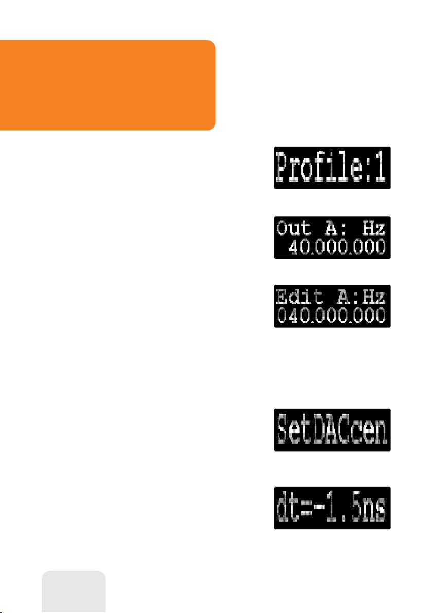
Setting output frequencies
To change profile number, press ⊖ or ⊕
button to select the Profile menu item, then hold
one of these buttons for approximately two seconds
to change the profile number.
For each of four profiles, you may change
frequencies for each of A…D outputs. With ⊖ or
⊕ button, select the desired output, and then hold
one these buttons to edit its frequency.
Menu description
An editable digit starts flashing. Short press ⊖
or ⊕ to select the digit to edit, or hold one of these
buttons to increment or decrement the selected
digit. Please make sure that the desired frequency is
inside the specifications of this GPSDO.
Press Menu to exit the editor mode.
Preferences
Select Prefs from the top menu, then hold ⊖ or
⊕ to enter the Preferences menu. Experienced
users may tweak several parameters of the GPSDO
here.
Checking the OCXO center frequency
First, use the SetDACcen menu to set the DAC
to its center value (32768).
Notice the value of the dt while in Hold mode. If
the value if out of the ±100 ns range, adjust the potentiometer (if installed) on the
printed circuit board to set is as close to zero as possible.
Tokenblauser 9
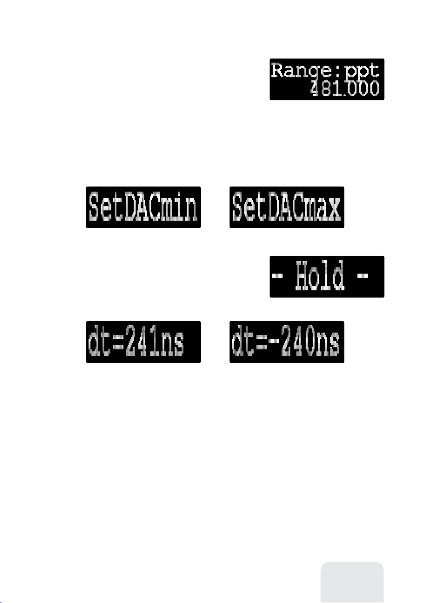
OCXO tuning range settings
To set the maximum tuning range of the OCXO,
select Range and hold ⊖ or ⊕ to change. The
tuning range is set in ppt (parts per trillion). It is
necessary to set the tuning range properly for the
algorithms to work correctly.
The OCXO tuning range is defined as a relative frequency change of the OCXO
when the DAC changes its value to from its minimum to its maximum. Use
SetDACmin and SetDACmax menus to control the DAC.
Hold ⊖ or ⊕ to set the 16-bit DAC in its
minimum (0) and then maximum (65535) value.
After applying this setting, the GPSDO will enter
the Hold mode, returning to the Status screen.
Notice the value of the dt while in Hold mode.
The value shows how much the output the 1PPS output of the GPS is ahead or
behind of the pulses of the internal OCXO. Positive values mean that the frequency
of the OCXO is lower than 10 MHz, and negative values mean higher OCXO
frequencies.
To find out the exact tuning range of the OCXO installed in your GPSDO, follow
this algorithm:
1) Set the DAC to its minimum value by using the SetDACmin menu. Write
down the dt value, such as 241ns.
2) By using the SetDACmax menu, choose maximum value. Again, write
down the dt value. Example: -240 ns.

1010 User's manual
With the above example, the tuning range of the OCXO (limited by resistor
network inside the GPSDO) is
241 + 240 = 481 ppb (parts per billion) -or- 481000 ppt (parts per trillion)
Enter the value 481000 ppt in the Range menu, for the PLL algorithm to work
properly. For OCXOs with negative control voltage characteristic, the Range value
will be negative.
Positive and negative control voltage characteristics
PLL settings
By using the Prefilter time constant, the Loop filter time constant and the
Damping factor menus, parameters of the phase locked loop may be tweaked, as
illustrated by the picture below.
Example loop filter settings: 100 sec – faster locking, less stable output (10–9).
500 sec – slower locking, more stable output (10–10).
Prefilter and PI-loop filter
Indice
Manuali Attrezzature da laboratorio popolari di altre marche


Agilent Technologies
Agilent Technologies 5800 ICP-OES Manuale utente

Endress+Hauser
Endress+Hauser Cleanfit CPA875 Manuale utente

NI
NI PXI-5422 Manuale

Collomix
Collomix Aqix Manuale utente

SPEX SamplePrep
SPEX SamplePrep 6875 Freezer/Mill Series Manuale utente

Ocean Insight
Ocean Insight FLAME-NIR+ Manuale utente


