Rikon Power Tools 50-112 Manuale utente

4” X 36”Belt / 6”Disc Sander
Model: 50-112
For more information:
www.rikontools.com or [email protected]
For Parts or Questions:
Record the serial number and date of purchase
in your manual for future reference.
Serial number:
Date of purchase:
Part # 50-112M1

IMPORTANT! Safety is the single most important consideration in the operation of this equipment.
The following instructions must be followed at all times.
There are certain applications for which this tool was designed. We strongly recommend that this tool
not be modied and/or used for any other application other than that for which it was designed. If you
have any questions about its application, do not use the tool until you have contacted us and we have
advised you. General Safety Warnings
KNOW YOUR POWER TOOL. Read the owner’s manual carefully. Learn the tool’s
applications, work capabilities, and its specic potential hazards.
ALWAYS KEEP VISITORS AWAY FROM RUNNING MACHINES.
All visitors should be kept a safe distance from the work area.
ALWAYS MAKE THE WORKSHOP CHILDPROOF.
Childproof with padlocks, master switches, or by removing starter keys.
NEVER OPERATE A TOOL WHILE UNDER THE INFLUENCE OF DRUGS,
MEDICATION, OR ALCOHOL.
ALWAYS WEAR PROPER APPAREL.
Never wear loose clothing or jewelry that might get caught in moving parts. Rubber-soled footwear is
recommended for the best footing.
ALWAYS USE SAFETY GLASSES AND WEAR HEARING PROTECTION.
Also use a face or dust mask if the cutting operation is dusty.
NEVER OVERREACH.
Keep your proper footing and balance at all times.
ALWAYS GROUND ALL TOOLS.
If your tool is equipped with a three-pronged plug, you must plug it into a three-hole electric receptacle.
If you use an adapter to accommodate a two-pronged receptacle, you must attach the adapter plug to a
known ground. Never remove the third prong of the plug.
ALWAYS AVOID DANGEROUS ENVIRONMENTS.
Never use power tools in damp or wet locations. Keep your work area well lighted and clear of clutter.
ALWAYS REMOVE THE ADJUSTING KEYS AND WRENCHES FROM TOOLS AFTER USE.
Form the habit of checking to see that keys and adjusting wrenches are removed from the tool before
turning it on.
ALWAYS KEEP YOUR WORK AREA CLEAN. Cluttered areas and benches invite accidents.
NEVER STAND ON TOOLS.
Serious injury could occur if the tool is tipped or if the cutting tool is accidentally
2
Operator Safety: Required Reading

ALWAYS CHECK FOR DAMAGED PARTS.
Before initial or continual use of the tool, a guard or other part that is damaged should be checked to
assure that it will operate properly and perform its intended function. Check for alignment of moving
parts, binding of moving parts, breakage of parts, mounting, and any other conditions that may affect its
operation. A guard or other damaged parts should immediately be properly repaired or replaced.
ALWAYS DISCONNECT TOOLS.
Disconnect tools before servicing and when changing accessories such as blades, bits, and cutters.
ALWAYS AVOID ACCIDENTAL STARTING.
Make sure switch is in “OFF” position before plugging in cord.
NEVER LEAVE TOOLS RUNNING UNATTENDED.
Special Safety Rules For Belt & Disc Sanders
SAVE THESE INSTRUCTIONS.
Refer to them often.
3
1. Do not operate this machine until you have read all of the following instructions.
2. Do not attempt to operate this machine until it is completely assembled.
3. Do not turn ON this machine if any pieces are missing.
4. If you are not familiar with the operation of the machine, obtain assistance from a qualied person.
5. It is highly recommended that this machine be rmly mounted to a at and secure work surface or
stand.
6. Always wear protective eyewear prior to operating this machine.
7. Do not operate this machine if you are under the inuence of drugs and/or alcohol.
8. Remove all jewelry prior to operating this machine.
9. Do not wear any gloves while operating this machine.
10. Always make sure the power switch is in the OFF position prior to plugging in the machine.
11. Always make sure the power switch is in the OFF position when doing any assembly or setup
operation.
12. Always wear a dust mask and use adequate dust collection and proper ventilation. Use of sanders can
produce harmful particles while sanding certain types of woods.
13. The use of any accessories or attachments not recommended may cause injury to you and damage
your machine.
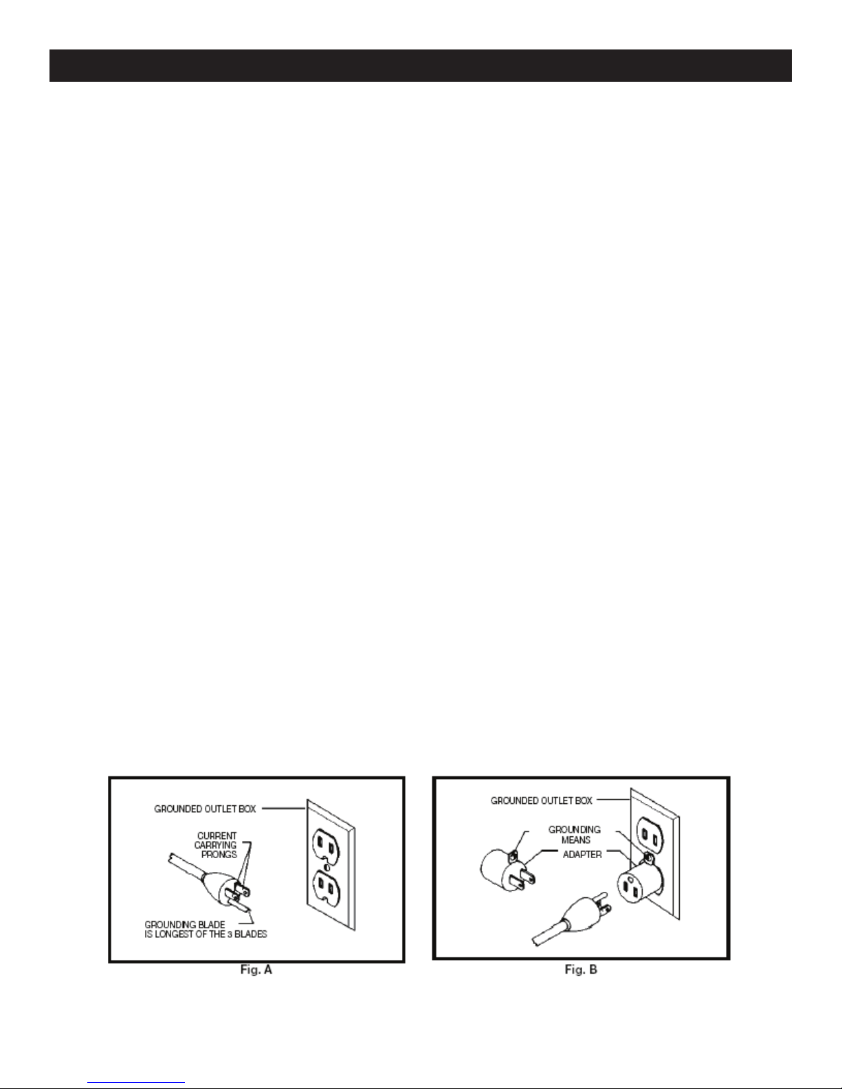
14. This machine must be properly grounded.
15. Abrasive discs and belts should be the recommended width and length of the manufacturer.
16. Always keep your face and hands clear of moving parts such as belts and pulleys.
17.Keep power supply cords free of moving parts of the sander. Damaged cords can result in electric
shock.
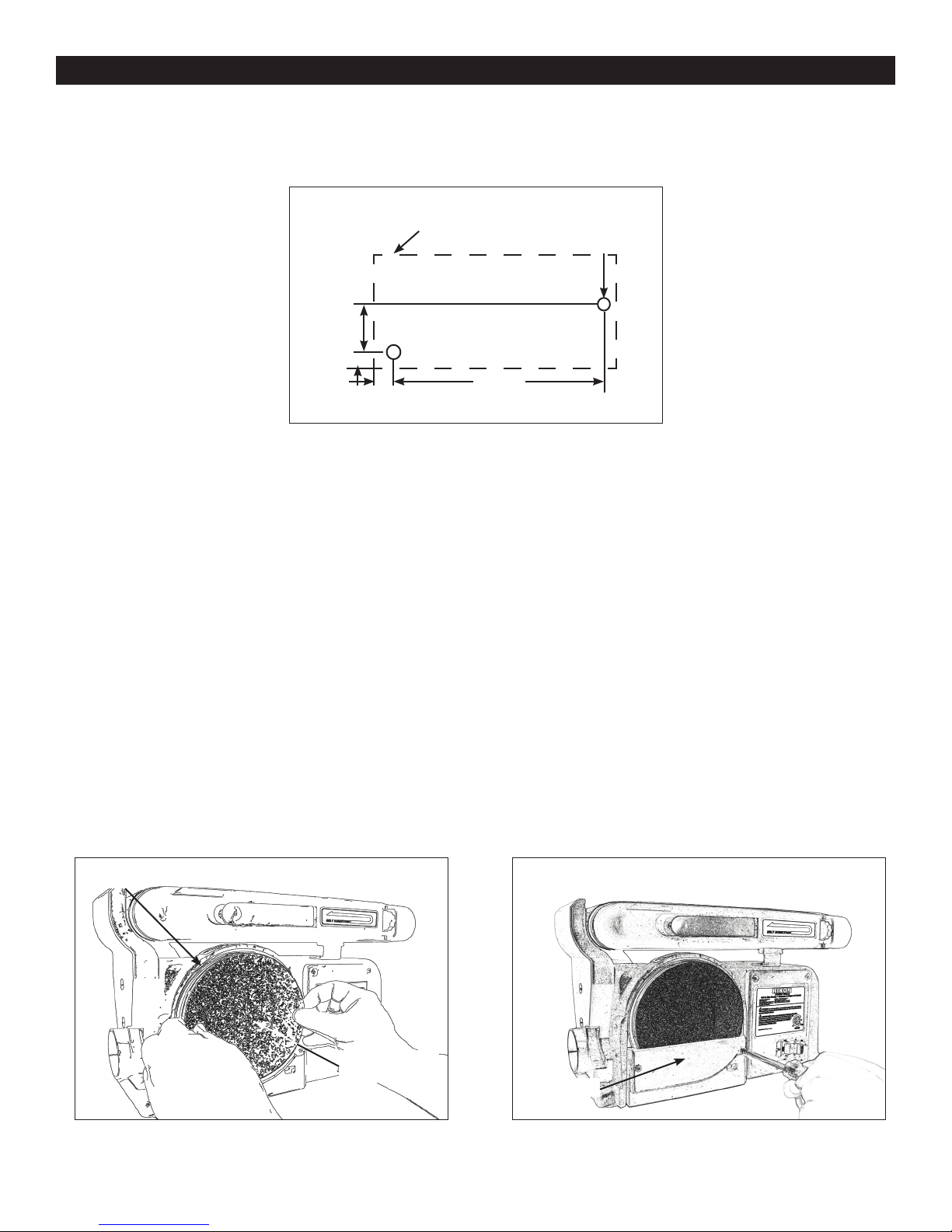
18. Maintain a 1/16” clearance between the sanding disc, sanding belt and tables
19.Always support the workpiece with the table or backstop.
20. Remove material or debris from the work area. Keep work area neat and clean.
21.Keep these instructions for future reference.
California Proposition 65 Warning
WARNING: Some dust created by power sanding, sawing, grinding, drilling, and other construction activities contains
chemicals known to the State of California to cause cancer and birth defects or other reproductive harm.Your risk from
exposure to these chemicals varies, depending on how often you do this type of work. To reduce your exposure, work in
a well-ventilated area and with approved safety equipment, such as dust masks that are specially designed to lter out
microscopic particles.
For more detailed information about California Propostion 65 log onto rikontools.com.

Safety Warnings..................................................................................................................................2-3
Sander Safety Rules ..........................................................................................................................3
Specications ........................................................................................................................................4
Unpacking ............................................................................................................................4
Assembly ...........................................................................................................................5
Mounting Sanding Disc and Guard.........................................................................................................5
Assembling the Work Support Fence..........................................................................................6
Table Support Assembly....................................................................................................................6
Mounting the Table Assembly..................................................................................................7
Operation ...........................................................................................................................................7
On/Off Switch ............................................................................................................................................8
Leveling the Table Assembly..........................................................................................................8
Installing the Sanding Belt ..........................................................................................................................9
Electrical Requirements.......................................................................................................................10
Wiring Diagram.................................................................................................................................11
Maintenance ...................................................................................................................................11-13
Timing Belt Replacement............................................................................................................................13
Trouble Shooting................................................................................................................................13
Parts List/Parts Explosion............................................................................................................................14-15
4
When unpacking, check to make sure the following parts are included. If any parts are missing
or broken, please call RIKON Power Tools at the number on the cover of this manual as soon as
possible. Item # Description Qty
---- Sander Body 1
35 Table 1
7 6” Sandpaper Disc 1
33 Table Support 1
6 Guard, Disc 1
60 Work Support 1
---- Miter Gauge 1
---- Plastic bag contains 1
assembly hardware.
4”x36”
1930 SFPM
6”
3420 SFPM
9” x 6-1/4”
0-90 o
45 o
1/2 HP
4.3
110
37 lbs
Belt Size
Belt Speed
Disc Size
Disc Speed
Table Size
Belt Table Tilt
Disc Table Tilt
Motor
Amps
Volts
Net weight
Notes/Warranty .............................................................................................................................................15-16
Table of Contents
Specications
Unpacking

5
Assembly
341mm
(13-7/16”)
OUTLINE OF
SANDER
2 HOLES
10mm(3/8” Diameter)
68mm
2-21/32”
19mm
(3/4”)
14mm
(9/16”)
Securing Sander Base Assembly to Workbench
Belt and disc sander must be fastened securely to a rm supporting surface such as a workbench.
1. Place sander in operational position on workbench.
2. Place a pencil through the holes in the sander base (42) and mark drill holes in workbench.
3. Remove sander and drill two 10mm (3/8”) dia. holes through the workbench.
4. Align sander base over holes and secure using two 5/16” screws and hex. nuts
Mounting Sanding Disc and Guard
1. Locate sanding disc (7) and peel backing off disc.
2. Align perimeter of sanding disc over plate. When aligned, press sandpaper disc rmly onto
backing disc.
3. Position disc guard (6) onto lower portion of sanding disc so that the mounting holes align.
4. Using a Phillips screwdriver, fasten two pan head screws (found in parts bag) over disc
guard.
Disc (10)
Pad, 6 inch
Sandpaper (7)
Disc Guard

6
Installing Work support
1. Place work support (60) over sanding belt as shown in following illustration.
2. Place the hex. screw (91) through the at washer (90)and secure. Do not over tighten.
Assembly
Table Support Assembly
1. Locate the table support (33) and hex. screws (31) and washers (32).
2. Stand table (35) on its side, aligning holes as shown in below illustration.
3. Fasten table support to table. Do not over tighten screws.
Wrench Work Support (60)
Table (35)Table Support (33)

7
Assembly
4. Position table support (33) in corresponding holes on side of base as shown in below
illustration.
5. Place washer (32) on knob (34) shaft and insert through slot into threaded holes in base.
6. Loosen the three hex. screws (31) and adjust table so that there is a maximum of 1.5mm
(1/16”) space between the sanding disc and the table. Tighten screws.
Index Pin
Table Support (33)
Base
Washer (32)
Knob (34)
Table Angle Scale
1/16 in. Max
between
Sanding surface and
Table Edge
Operation
The rocker ON/OFF power switch is located on the front of the sander, and incorporates a removable
safety switch.
1. Press the side marked ON to turn the sander on.
2. Press the side marked OFF to turn the sander off.
In situations where the sander may be left unattended, the operator has the option of removing the
center safety portion of the ON/OFF switch to render the sander inoperable. When the operator is
ready to use the machine again, the center safety portion of the switch may be reinstalled simply by
inserting it into the opening in the switch and pushing it in until it “seats”.

8
Operation
Remounting Table for Vertical Sanding
1. Remove backstop lock bolt and remove work support.
2. Unscrew knob (34) and remove.
3. Pull table support (33) index pin out of mounting hole.
4. Loosen hex socket screw (75) and raise sanding bed to the desired sanding position.
5. Insert the table index pins into the auxiliary (upper) holes in the sanding bed.
6. Tighten hex socket screw (75). Make sure table is not touching sanding belt.
Leveling Table Assembly
1. Place a combination square on the table (35) so that it also touches the sanding pad (7).
See below. If the table is 90 degrees to the pad, the square is ush on the pad.
2. If the table is not 90 degrees to the with the pad, loosen the table lock knob (34) and tilt the
table until the square is ush with the pad
3. Retighten the knob to secure the table.
4. Attach the scale label to the ‘0’ degrees mark on the dust guard.
Auxiliary
Mounting
Holes
Table
Support
Knob (1)
Scale Label Table Lock Knob (34)
Table (35)

9
Operation
Installing and Adjusting the Sanding Belt
1. Turn power switch to the OFF position and disconnect power cord from the main elec
tricity supply.
2. Move tension lever (66) to the right to release the sanding belt tension (10). .
3. Place the sanding belt over the drive and idler drums (13 and 65), making sure that the
inside direction arrow points down, towards the drive drum (13) as shown in illustration..
4. Centre belt on both drums.
5. Slide tension lever (66) to the left to tighten belt tension.
6. Tighten hex. socket screw (56) when bed (4) is in desired working position.
7. Reconnect the power cord to the main electricity supply. Turn the no-volt release switch
(21) ON, then OFF, while viewing the belt movement. If the belt looks like it was going
to slide off either drum, the belt tracking needs to be adjusted (described in the next
step).
8. If the sanding belt (87) moves towards the sanding pad (7) when turned ON, turn the
tracking knob (55) clockwise ¼ turn, and test again.
9. If the sanding belt moves away from the sanding pad when it was turned ON, turn he
tracking knob counterclockwise ¼ turn, and test again.
Surface Sanding on Sanding Belt End Sanding on Sanding Belt
Sanding Curved Edges

In the event of a malfunction or breakdown, grounding provides a path of least resistance for electric
current to reduce the risk of electric shock. This tool is equipped with an electric cord having an
equipment-grounding conductor and a grounding plug. The plug must be plugged into a matching
outlet that is properly installed and grounded in accordance with all local codes and ordinances.
Do not modify the plug provided. If it will not t the outlet, have the proper outlet installed by a
qualied electrician.
Improper connection of the equipment-grounding conductor can result in a risk of electric shock. The
conductor, with insulation having an outer surface that is green with or without yellow stripes, is the
equipment-grounding conductor. If repair or replacement of the electric cord or plug is necessary, do
not connect the equipment-grounding conductor to a live terminal.
Check with a qualied electrician or service personnel if the grounding instructions are not completely
understood, or if in doubt as to whether the tool is properly grounded.
Use only three wire extension cords that have three-prong grounding plugs and three-pole
receptacles that accept the tool’s plug.*
Repair or replace a damaged or worn cord immediately.
This tool is intended for use on a circuit that has an outlet that looks the one illustrated in Figure
A below. The tool has a grounding plug that looks like the grounding plug as illustrated in Figure A
below. A temporary adapter, which locks like the adapter as illustrated in Figure B below, may be
used to connect this plug to a two-pole receptacle, as shown in Figure B if a properly grounded outlet
is not available.** The temporary adapter should only be used until a properly grounded outlet can
be installed by a qualied electrician. The green colored rigid ear or tab, extending from the adapter,
must be connected to a permanent ground such as a properly grounded outlet box.
* Canadian electrical codes require extension cords to be certied SJT type or better.
** Use of an adapter in Canada is not acceptable.
Electrical Requirements
10
Indice
Altri manuali Rikon Power Tools Levigatrice

Rikon Power Tools
Rikon Power Tools 50-144 Manuale utente

Rikon Power Tools
Rikon Power Tools 50-120 Manuale utente

Rikon Power Tools
Rikon Power Tools 50-161VS Manuale utente

Rikon Power Tools
Rikon Power Tools 50-151 Manuale utente

Rikon Power Tools
Rikon Power Tools 31-200 Manuale utente

Rikon Power Tools
Rikon Power Tools 50-142 Manuale utente

Rikon Power Tools
Rikon Power Tools 51200 Manuale utente

Rikon Power Tools
Rikon Power Tools 50-142 Manuale utente

Rikon Power Tools
Rikon Power Tools 51200 Manuale utente

Rikon Power Tools
Rikon Power Tools 50-120 Manuale utente


