Royal R-3500TR Istruzioni per il montaggio
1
Installers Guide
544-981D 3/00
- Do not store or use gasoline or other flam-
mable vapors and liquids in the vi inity of this
or any other applian e.
-What to do if you smell gas
Do not try to light any applian e.
Do not tou h any ele tri al swit h.
Do not use any phone in your building.
Immediately all your gas supplier from a
neighbor's phone. Follow the gas supplier's in-
stru tions.
If you annot rea h your gas supplier, all the
fire department.
- Installation and servi e must be performed by a
qualified installer, servi e agen y, or the gas
supplier.
WARNING: IMPROPER INSTALLA-
TION, ADJUSTMENT, ALTERATION,
SERVICE OR MAINTENANCE CAN
CAUSE INJURY OR PROPERTY DAM-
AGE. REFER TO THIS MANUAL. FOR
ASSISTANCE OR ADDITIONAL IN-
FORMATION CONSULT A QUALIFIED
INSTALLER, SERVICE AGENCY, OR
THE GAS SUPPLIER.
Underwriters
Laboratories Listed
READ THIS MANUAL BEF RE INSTALLING R
PERATING THIS APPLIANCE. THIS INSTALLERS
GUIDE MUST BE LEFT WITH THE APPLIANCE F R
FUTURE REFERENCE.
1. This appliance may be installed in an after-
market, permanently located, manufactured
(mobile) home, where not prohibited by lo-
cal codes.
2. This appliance is only for use with the type
of gas indicated on the rating plate. This
appliance is not con ertible for use with
other gases, unless a certified kit is used.
WARNING: IF THE INFORMATION
IN THESE INSTRUCTIONS IS NOT
FOLLOWED EXACTLY, A FIRE OR
EXPLOSION MAY RESULT CAUS-
ING PROPERTY DAMAGE, PER-
SONAL INJURY, OR DEATH.
This product is covered by one or more of the following patents: (United States) 4, 2,9 3; 4,408,594; 4,422,426; 4,424,792; 4,520,79 ; 4,793,322;
,852,548; 4,875,464; 5,000, 62; 5,0 6,609; 5,076,254 5, 9 ,877; 5,2 8,953; 5,328,356; 5,429,495; 5,452,708; 5,542,407; 5,6 3,487; (Australia)
543790; 586383; (Canada) , 23,296; ,297,746; 2, 95,264; (Mexico) 97-0457; (New Zealand) 200265; or other U.S. and foreign patents pending.
Models:
R-3500TR
R-3500TRH
R-4500TR
R-4500TRH
R-6500TR
Please contact your Royal Fireplaces dealer for any
questions or concerns. For the number of your nearest
Royal Fireplaces dealer, please call 1-800-3 3- 484.
Printed in U.S.A. Copyright 2000,
Hearth Technologies Inc.
20802 Kensington Blvd., Lakeville, MN 55044
®
2
SAFETY AND WARNING INFORMATION
READ and UNDERSTAND all instructions carefully before starting the installation.
FAILURE TO FOLLOW these installation instructions may result in a possible fire
hazard and will void the warranty.
Prior to the first firing of the fireplace, READ the Using Your Fireplace section of the
Owners Guide.
DO NOT USE this appliance if any part has been under water. Immediately CALL a
ualified service technician to inspect the unit and to replace any part of the control
system and any gas control which has been under water.
THIS UNIT IS NOT FOR USE WITH SOLID FUEL.
Installation and repair should be PERFORMED by a ualified service person. The
appliance and venting system should be INSPECTED before initial use and at least
annually by a professional service person. More fre uent cleaning may be re uired due
to excessive lint from carpeting, bedding material, etc. It is IMPERATIVE that the units
control compartment, burners, and circulating air passageways BE KEPT CLEAN to
provide for ade uate combustion and ventilation air.
Always KEEP the appliance clear and free from combustible materials, gasoline, and
other flammable vapors and li uids.
NEVER OBSTRUCT the flow of combustion and ventilation air. Keep the front of the
appliance CLEAR of all obstacles and materials for servicing and proper operations.
Due to the high temperature, the appliance should be LOCATED out of traffic areas
and away from furniture and draperies. Clothing or flammable material SHOULD NOT
BE PLACED on or near the appliance.
Children and adults should be ALERTED to the hazards of high surface temperature
and should STAY AWAY to avoid burns or clothing ignition. Young children should be
CAREFULLY SUPERVISED when they are in the same room as the appliance.
These units MUST use one of the vent systems described in the Installing the
Fireplace section of the Installers Guide. NO OTHER vent systems or components
MAY BE USED.
This gas fireplace and vent assembly MUST be vented directly to the outside and
MUST NEVER be attached to a chimney serving a separate solid fuel burning
appliance. Each gas appliance MUST USE a separate vent system. Common vent
systems are PROHIBITED.
INSPECT the external vent cap on a regular basis to make sure that no debris is
interfering with the air flow.
The glass door assembly MUST be in place and sealed, and the trim door assembly
MUST be in place on the fireplace before the unit can be placed into safe operation.
DO NOT OPERATE this appliance with the glass door removed, cracked, or broken.
Replacement of the glass door should be performed by a licensed or ualified service
person. DO NOT strike or slam the glass door.
The glass door assembly SHALL ONLY be replaced as a complete unit, as supplied
by the gas fireplace manufacturer. NO SUBSTITUTE material may be used.
DO NOT USE abrasive cleaners on the glass door assembly. DO NOT ATTEMPT to
clean the glass door when it is hot.
Turn off the gas before servicing this appliance. It is recommended that a ualified
service technician perform an appliance check-up at the beginning of each heating
season.
Any safety screen or guard removed for servicing must be replaced before operating
this appliance.
!
!
!
!
!
!
!
!
!
!
!
!
!
!
!
!
!
!

3
Table of
Contents
Safety and Warning Information ................................ 2
Section 1: Approvals and Codes ............................... 4
Approval Listings and Codes .................................... 4
Appliance Certification ............................................... 4
Installation Codes ...................................................... 4
High Altitude Installations ........................................... 5
Section 2: Getting Started ......................................... 6
Introducing the Royal Fireplaces ............................... 6
Pre-installation Preparation ....................................... 6
Section : Installing the Fireplace ........................... 10
Step 1 Locating the Fireplace ............................... 10
Step 2 Framing the Fireplace ............................... 11
Step 3 Installing the Vent System ......................... 12
A. Vent System Approvals ......................... 12
B. Installing Vent Components................... 30
C. Vent Termination ................................... 36
Step 4 Positioning, Leveling, and
Securing the Fireplace .............................. 41
Step 5 The Gas Control Systems ......................... 41
Step 6 The Gas Supply Line ................................. 42
Step 7 Gas Pressure Requirements .................... 43
Step 8 Wiring the Fireplace .................................. 44
Step Finishing .................................................... 46
Step 10 I
nstalling Trim, Logs, and Ember Materia
l ... 47
Installing the Trim ...................................... 47
Positioning the Logs .................................. 48
Placing the Ember Material ....................... 48
Step 11 Before Lighting the Fireplace ..................... 50
Step 12 Lighting the Fireplace ................................ 50
After the Installation ................................... 50
Section 4: Maintaining and Servicing
Your Fireplace ........................................ 51
Section 5: Replacement Parts
and Accessories ...................................... 5
Replacement Parts ................................................. 53
Accessories ............................................................ 58
u = Contains updated information.
u
u
u
u
u

4
Approval Listings
and Codes
Appl ance Cert f cat on
The Royal Fireplaces models discussed
in this
Installers Guide have been tested to certification
standards and listed by the applicable laboratories.
CERTIFICATION
MODEL LABORATORY TYPE STANDARD
R-6500TR Underwriters Direct Vent ANSI Z21.50CGA2.22
Laboratories Gas Fireplace
R-4500TR Underwriters Direct Vent ANSI Z21.50 CGA2.22
Laboratories Gas Fireplace
R-4500TRH Underwriters Direct Vent ANSI Z21.88 CGA2.33
Laboratories Gas Fireplace
Heater
R-3500TR Underwriters Direct Vent ANSI Z21.50CGA2.22
Laboratories Gas Fireplace
R-3500TRH Underwriters Direct Vent ANSI Z21.88 CGA2.33
Laboratories Gas Fireplace
Heater
NOTE: ALL MODELS ARE UL LISTED TO UL307B, THE STANDARD
FOR GAS-BURNING HEATING APPLIANCES FOR MANUFACTURED
HOMES AND RECREATIONAL VEHICLES.
Installat on Codes
The fireplace installation must conform to local codes. Before installing the
fireplace, consult the local building code agency to ensure that you are in
compliance with all applicable codes, including permits and inspections.
In the absence of local codes, the fireplace installation must conform to the
National Fuel Gas Code ANSI Z223.1 (in the United States) or the CAN/CGA-
B14 Installation Codes (in Canada). The appliance must be electrically
grounded in accordance with local codes or, in the absence of local codes with
the National Electric Code ANSI/NFPA No. 70 (in the United States), or to the
CSA C22.1 Canadian Electric Code (in Canada).
These models may be installed in a bedroom or bed-sitting room in the U.S.A.
and Canada.
1
Approvals
and Codes

5
H gh Alt tude Installat ons
U.L. Listed gas fireplaces are tested and approved for elevations from 0 to
2,000 feet in the U. S. A. and from 0 to 4,500 feet in Canada.
When installing this fireplace at an elevation above 2,000 feet (in the United
States), it may be necessary to decrease the input rating by changing the
existing burner orifice to a smaller size. Input should be reduced four percent
(4%) for each 1,000 feet above sea level, unless the heating value of the gas
has been reduced, in which case this general rule will not apply. To identify the
proper orifice size, check with the local gas utility.
When installing this fireplace at an elevation between 2,000 and 4,500 feet (in
Canada), the input rating must be reduced by ten percent (10%).
When installing this fireplace at an elevation above 4,500 feet (in Canada),
check with local authorities.
Consult your local gas utility for assistance in determining the proper orifice for
your location.

6
2
Getting
Started
Introducing the
Royal Fireplaces
Royal Fireplaces direct vent gas fireplaces are
designed to operate with all combustion air
siphoned from outside of the building and all
exhaust gases expelled to the outside.
The information contained in this Installers Guide,
unless noted otherwise, applies to all models and
gas control systems.
Gas fireplace diagrams, including the dimensions,
are shown in this section.
Pre-installation
Preparation
This gas fireplace and its components are tested
and safe when installed in accordance with this
Installers Guide. Report to your dealer any parts
damaged in shipment, particularly the condition of
the glass. Do not install any unit with damaged,
incomplete, or substitute parts.
The vent system components and trim doors are
shipped in separate packages. The gas logs are
packaged separately and must be field installed.
Read all of the instructions before starting the
installation. Follow these instructions carefully
during the installation to ensure maximum
safety and benefit. Failure to follow these
instructions will void the owners warranty and
may present a fire hazard.
The Royal Fireplaces warranty will be voided by,
and Hearth Technologies Inc. disclaims any
responsibility for, the following actions:
Installation of any damaged fireplace or vent
system component.
Modification of the fireplace or direct vent system.
Installation other than as instructed by Hearth
Technologies Inc.
Improper positioning of the gas logs or the glass
door.
Installation and/or use of any component part not
manufactured and approved by Hearth Technolo-
gies Inc. not withstanding any independent testing
laboratory or other party approval of such compo-
nent part or accessory.
ANY SUCH ACTION MAY POSSIBLY CAUSE A
FIRE HAZARD.
7
Figure 1. Diagram of the R-6500TR
When planning a fireplace installation, its necessary to determine:
Where the unit is to be installed.
The vent system configuration to be used.
Gas supply piping.
Electrical wiring.
Framing and finishing details.
Whether optional accessoriesdevices such as a fan, wall switch, or remote
controlare desired.
If the fireplace is to be installed on carpeting or tile, or on any combustible
material other than wood flooring, the fireplace should be installed on a metal or
wood panel that extends the full width and depth of the fireplace.
GAS
LINE
ACCESS
5 3/8
(138mm)
2 1/4
(56mm)
41 3/4
(1061mm)
48 (1218mm)
43 (1091mm)
23 1/2
(597mm)
38 1/2
(978mm)
3 1/2 (90mm)
ELECTRICAL
ACCESS
28 1/2
(724mm)
8 5/8
(219mm)
VENT
COLLARS
DIAMETER
8
(203mm)
18 7/8
(479mm)
6 5/8 (168mm)
VENT COLLARS
DIAMETER 8 3/4 (222mm)
16 1/4 (413mm)
37 3/4 (957mm)
GAS
ACCESS
LOWER GRILLE
RATING PLATE/
LABELS
HOOD
TRIM
DOOR
GAS
CONTROLS
ELECTRICAL
ACCESS
TOP
STANDOFFS
8
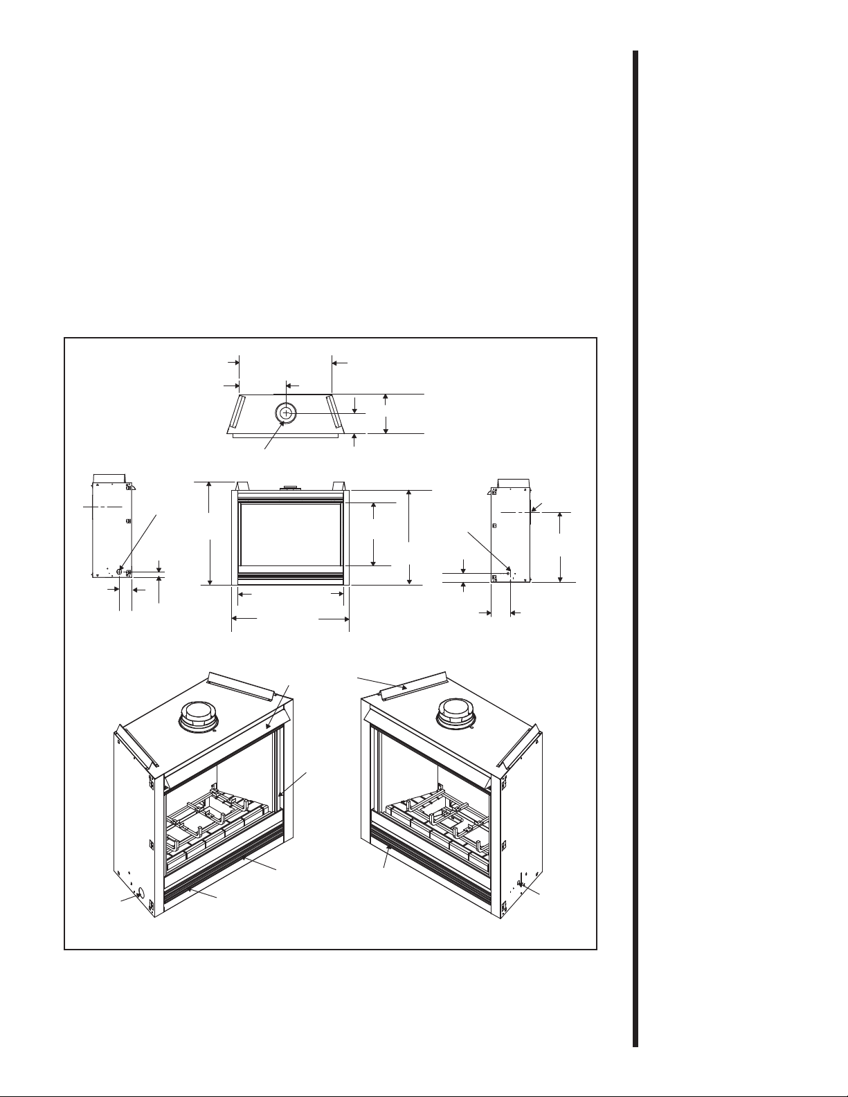
Figure 2. Diagram of the R-4500TR/TRH
GAS
ACCESS
LOWER GRILLE
RATING PLATE/
LABELS
HOOD
TRIM
DOOR
GAS
CONTROLS
ELECTRICAL
ACCESS
TOP
STANDOFFS
5 3/8 (138mm)
GAS
LINE
ACCESS
2 1/4 (56mm)
37 3/4
(960mm)
36
(913mm)
41 (1040mm)
22
(560mm)
34 1/2
(876mm)
3 1/2
(90mm) 8 (203mm)
24 1/2
(623mm)
8 5/8
(219mm)
VENT
COLLARS
DIAMETER
ELECTRICAL
ACCESS
6 5/8 (168mm)
VENT COLLARS
DIAMETER 8 3/4 (222mm)
16 1/4 (413mm)
15 3/8 (390mm)
30 3/4 (781mm)
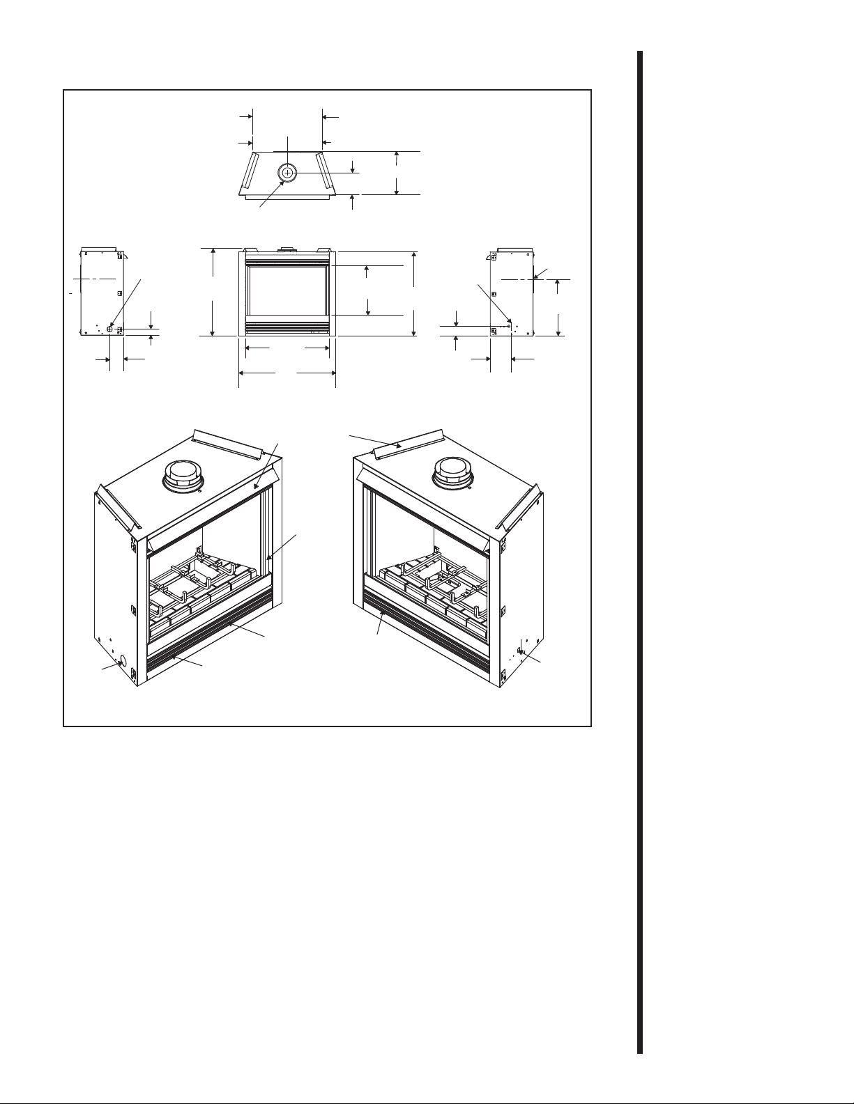
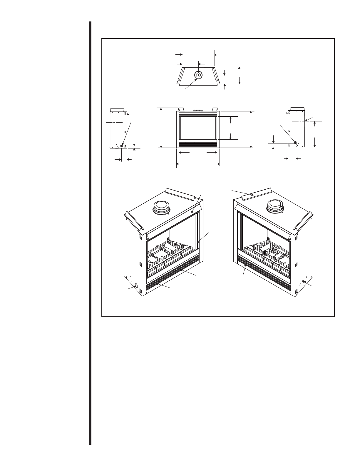
Figure . Diagram of the R- 500TR/TRH
GAS
ACCESS
LOWER GRILLE
RATING PLATE/
LABELS
HOOD
TRIM
DOOR
GAS
CONTROLS
ELECTRICAL
ACCESS
TOP
STANDOFFS
8
(203mm)
21
(533mm)
8 5/8
(219mm)
VENT
COLLARS
DIAMETER
ELECTRICAL
ACCESS
3 1/2
(90mm)
36
(913mm)
31
(788mm)
18 3/8
(468mm)
31
(786mm)
32 1/2
(826mm)
5 3/8
(138mm)
GAS
LINE
ACCESS
2 1/4
(56mm)
8 3/4 (222mm)
16 1/4 (413mm)
6 5/8 (168mm)
VENT COLLARS
DIAMETER
12 7/8
(327mm)
25 3/4 (653mm)
10
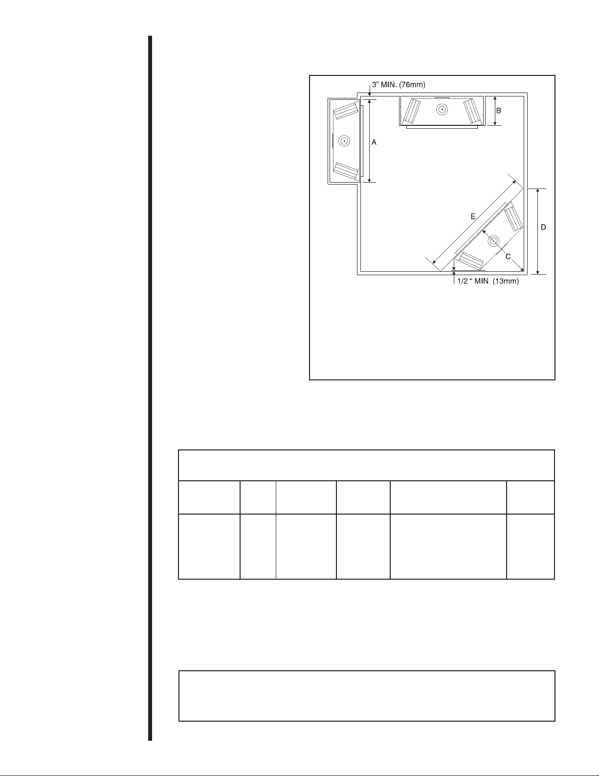
AB C D E
R-6500TR 49 16 1/4 35 3/8 50 70 3/4
R-4500TR & 42 16 1/4 31 7/8 45 63 3/4
R-4500TRH
R-3500TR & 37 16 1/4 29 3/8 41 1/2 58 3/4
R-3500TRH
NOTE: DIMENSIONS SHOWN IN INCHES.
Figure 4. Fireplace Dimensions, Locations,
and Space Requirements
Clearance Requirements
The top and back of the fireplace are defined by stand-offs.
MODELS RECESSED
DEPTH
R-6500TR, R-4500TR & R-4500TRH, R-3500TR & R-3500TRH 16 1/4
*The clearance to the ceiling is measured from the top of the unit, excluding
the standoffs and collar. (see Figure 42).
The minimum clearance to a perpendicular wall extending past the face of the
fireplace is 3 inches (76.2mm).
The back of the fireplaces may be recessed into combustible construction, as
shown below.
Minimum Clearances from the Fireplace to
Combustible Materials
Glass Back of Sides of Top of
Front Floor Fireplace Fireplace Fireplace Ceiling*
36 inches 0 1/2 inch 1/2 inch
( 14 mm) (13mm)
31 inches
(787mm)
(13mm)
R-3500 TR &
R-3500 TRH: 11/2 (38mm)
R-4500TR &
R-4500TRH: 3 1/4 (83mm)
R-6500TR: 3 1/4 (83mm)
3
Installing the
Fireplace
The diagram below shows space and clearance
requirements for locating a fireplace within a room.
Step
Locating the
Fireplace
Altri manuali per R-3500TR
1
Questo manuale è adatto per i seguenti modelli
4
Indice
Altri manuali Royal Camino da interno


