
RuggedCom RuggedWireless RS900W Family Manuale utente

RuggedCom Inc. I30 Whitmore Road, Woodbridge, Ontario, Canada L4L 7Z4
Tel: (905) 856-5288 I Fax: (905) 856-1995 IToll Free: (888) 264-0006
Rugged
RuggedRugged
RuggedWireless
WirelessWireless
Wireless
R
RR
RS
SS
S900
900900
900W
WW
W Family
Family Family
Family
Installation Guide
www.ruggedcom.com

2
2008 RuggedCom Inc. All rights reserved Rev103
Federal Communications Commission
Radio Frequency Interference Statement
This equipment has been tested and found to comply with the limits for a Class A digital device
pursuant to Part 15 of the FCC Rules These limits are designed to provide reasonable protection
against harmful interference when the equipment is operated in a commercial environment This
equipment generates, uses and can radiate radio frequency energy and, if not installed and used in
accordance with the instruction manual, may cause harmful interference to radio communications
Operation of this equipment in a residential area is likely to cause harmful interference in which
case the user will be required to correct the interference at his expense
Trademarks:
Ethernet is a trademark of Xerox Corporation
RuggedSwitch, RuggedRated, ROS and eRSTP are trademarks of RuggedCom® Inc
Caution
This product contains a laser system and is classified as a “CLASS 1 LASER PRODUCT”
Use of controls or adjustments or performance of procedures other than those specified herein
may result in hazardous radiation exposure This product contains no user serviceable parts
Attempted service by unauthorized personnel shall render all warranties null and void
Should this device require service see the “Warranty” section of this installation guide
Important
This unit should be installed in a restricted access location where access can only be gained by
service personnel or users who have been instructed about the reasons for the restrictions
applied to the location and about any precautions that shall be taken; and access is through the
use of a tool or lock and key, or other means of security, and is controlled by the authority
responsible for the location

3
2008 RuggedCom Inc. All rights reserved Rev103
Table of Contents
1Product Overvie .................................................................................................................. 4
1.1 Functional Overview ....................................................................................................... 4
1.2 Feature Highlights........................................................................................................... 4
1.3 RS900 Family Front Panel View.................................................................................. 5
1.4 RS900 Family Bottom Panel View............................................................................... 6
2Installation ............................................................................................................................. 7
2.1 DIN Rail Mounting........................................................................................................... 7
2.2 Power Supply iring and Grounding.............................................................................. 8
2.2.1 AC Power Supply iring and Grounding.................................................................... 8
2.2.2 DC Power Supply iring and Grounding ................................................................... 9
2.3 Dielectric Strength (HIPOT) Testing ............................................................................. 10
2.4 Failsafe Output iring and Specifications .................................................................... 11
2.5 RS232 Port iring........................................................................................................ 12
2.6 RJ45 Ports – Signal Description ................................................................................... 13
3Technical Specifications..................................................................................................... 14
3.1 Operating Environment................................................................................................. 14
3.2 Power Supply Specifications......................................................................................... 14
3.3 Failsafe Relay Specifications........................................................................................ 14
3.4 RJ45 Ethernet Port Specifications ................................................................................ 15
3.5 ireless Standards Supported ..................................................................................... 16
3.6 Radio Characteristics.................................................................................................... 16
3.7 IEEE 802.11b/g............................................................................................................. 17
3.8 Fiber Optical Port Specifications................................................................................... 18
3.9 Physical Dimensions..................................................................................................... 19
3.10 Agency Approvals......................................................................................................... 20
4Warranty............................................................................................................................... 20
5Appendix A - RuggedWireless ™ Frequently Asked Questions (FAQ)........................... 21

4
2008 RuggedCom Inc. All rights reserved Rev103
1 Product Overview
1.1 Functional Overview
The Rugged ireless RS900 family of products are industrially hardened, fully managed, IEEE
802.11g Access Points with integrated Ethernet switching, specifically designed to operate reliably
in electrically harsh and climatically demanding industrial environments. The RS900 ’s superior
ruggedized design coupled with the RS900 ’s Rugged ireless Operating System (ROS)
provides improved system reliability and advanced networking features making it ideally suited for
creating 802.11g ireless Ethernet networks for mission-critical, real-time, control applications.
The RS900 can be equipped with dual 100Mbps fiber optical Ethernet ports for creating a fiber
optical backbone with high noise immunity and long haul connectivity. The RS900 also provides
dual power inputs for backup power and is packaged in a rugged steel enclosure that can be DIN
rail or panel mounted.
1.2 Feature Highlights
Complies with the IEEE 802.11g 2.4GHz specification ( ireless LAN) including “fallback”
(backward) compatibility with IEEE802.11b station-client devices.
High wireless data rates: 54, 48, 36, 24, 18, 12, 11, 5.5, 2 and 1Mbps network speed.
The R 80 Access Point functionality will seamlessly integrate wireless and wired Ethernet
LAN networks.
Auto rate fallback in case of obstacles or interferences.
Basic security is provided with 64/128-bit EP Data Encryption function to protect the wireless
data transmissions.
Enhanced security is provided by PA and TKIP data-encryption method.
Robust security is provided by 802.11i/ PA2 (backward compatible with PA stations) and
AES (with CCMP) data-encryption method.
Both PA and PA2 modes both feature Enterprise and Personal configurations for key
management. Enterprise mode will offer IEEE 802.1x security (EAP with RADIUS) while
Personal offers Pre-Shared Key (PSK) “passphrase” to generate keys for authentication.
Integrated ROS™ configuration methods.
Exceeds IEC 61000-6-2 standards for industrial environments and NEMA TS-2 standards for
traffic control equipment.
Operating temperature: -40° to 85°C (no fan)
Power supply options: 12, 24 or 48VDC, and universal HI (88-300VDC or 84-264VAC)
Dual, independent inputs for 24 and 48VDC power supplies for redundancy
Failsafe output relay for critical failure or error alarming
Advanced layer-2 switching functions: Rapid Spanning Tree, Message Prioritization and Virtual
LANs
Full-duplex operation (no collisions) with flow-control

5
2008 RuggedCom Inc. All rights reserved Rev103
1.3 RS900W Family Front Panel View
Figure 1 - Front Panel Description
ITEM Activity Comments
Solid Link Established LINK LED (Yellow)
Blinking – Once per second Tx/Rx Activity
Power LED Solid Po er On
Alarm LED Solid Alarm condition exists
Table 1 - Status LEDs
Fail
-
Safe Relay
Po er Port
Port 9:
Antenna #2
Port 9:
Antenna #1
Ports 1
–
6:
10/100 BaseTx
Ports 7
–
8:
10/100 BaseTx
or
100 BaseFx
Po er and
Alarm LEDs
Reset LED

6
2008 RuggedCom Inc. All rights reserved Rev103
1.4 RS900W Family Bottom Panel View
Figure 2 - Bottom Panel Description
Chassis ground
Po er Supply
Connection
Optional DIN Rail
Mounting Bracket
Fail
-
Safe Relay
Connection
RS232 Console
Port
7
2008 RuggedCom Inc. All rights reserved Rev103
2 Installation
2.1 DIN Rail Mounting
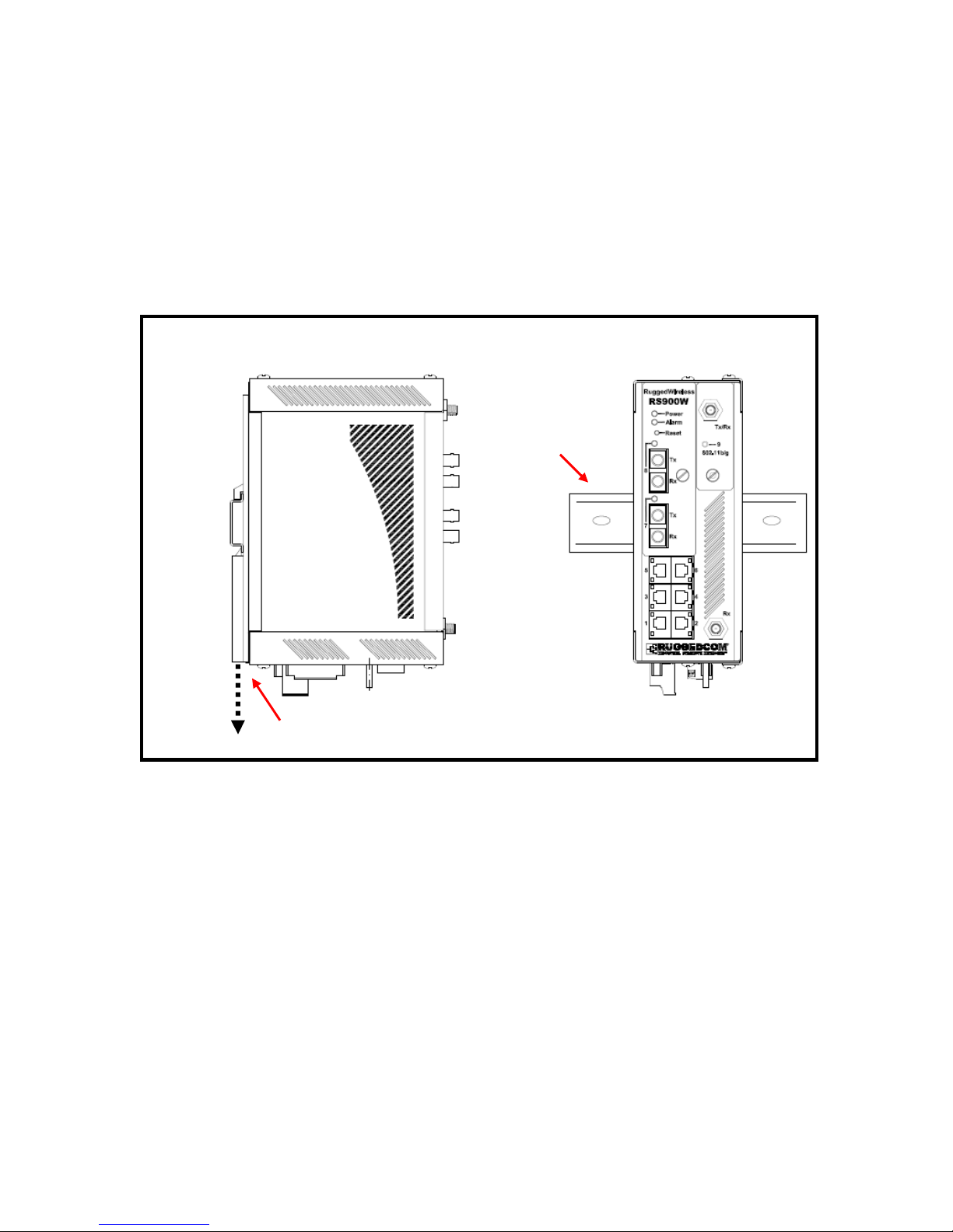
An optional DIN rail mounting bracket is available for the RS900 . Figure 2.1.1 details mounting
instructions for the standard 1” DIN Rail.
Figure 3 - DIN Rail Mounting
Din Rail
Din Rail
Optional
Din Rail
mounting
bracket
Release latch
Release
direction
8
2008 RuggedCom Inc. All rights reserved Rev103
2.2 Power Supply Wiring and Grounding
2.2.1 AC Power Supply Wiring and Grounding
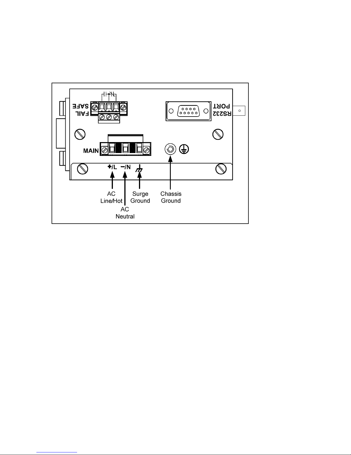
Figure 4 - Po er Supply Inputs
The AC power supply inputs should be connected as follows:
1. +/L should be connected to AC Line/Hot.
2. -/N should be connected to AC Neutral.
3. Surge Ground should be connected to the Chassis Ground via a braided cable or other
appropriate grounding wire. Surge Ground is used as the ground conductor for all surge
and transient suppression circuitry internal to the unit.
4. Chassis Ground must be connected to the AC ground terminal.
NOTES:
1. Equipment must be installed according to the applicable country wiring codes.
2. All line-to-ground transient energy is shunted to the Surge Ground terminal. In cases
where users require the inputs to be isolated from ground, remove the ground braid
between Surge and Chassis Ground. Note that all line-to-ground transient protection
circuitry will be disabled.

9
2008 RuggedCom Inc. All rights reserved Rev103
2.2.2 DC Power Supply Wiring and Grounding
Figure 5 - DC Po er supply iring and grounding diagram
The low voltage DC power supply features reverse polarity protection and dual independent inputs.
The latter feature allows the connection of two DC sources with the same nominal voltage to
provide redundant power supply inputs.
The DC power supply inputs should be connected as follows:
1. Connect to the DC inputs according to the polarity markings on the unit.
2. Surge Ground should be connected to the Chassis Ground via a braided cable or other
appropriate grounding wire. Surge Ground is used as the ground conductor for all surge
and transient suppression circuitry internal to the unit.
3. Chassis Ground must be connected to the protective earth.
NOTES:
1. Equipment must be installed according to the applicable country wiring codes.
2. All line-to-ground transient energy is shunted to the Surge Ground terminal. In cases
where users require the inputs to be isolated from ground, remove the ground braid
between Surge and Chassis Ground. Note that all line-to-ground transient protection
circuitry will be disabled.
10
2008 RuggedCom Inc. All rights reserved Rev103
2.3 Dielectric Strength (HIPOT) Testing
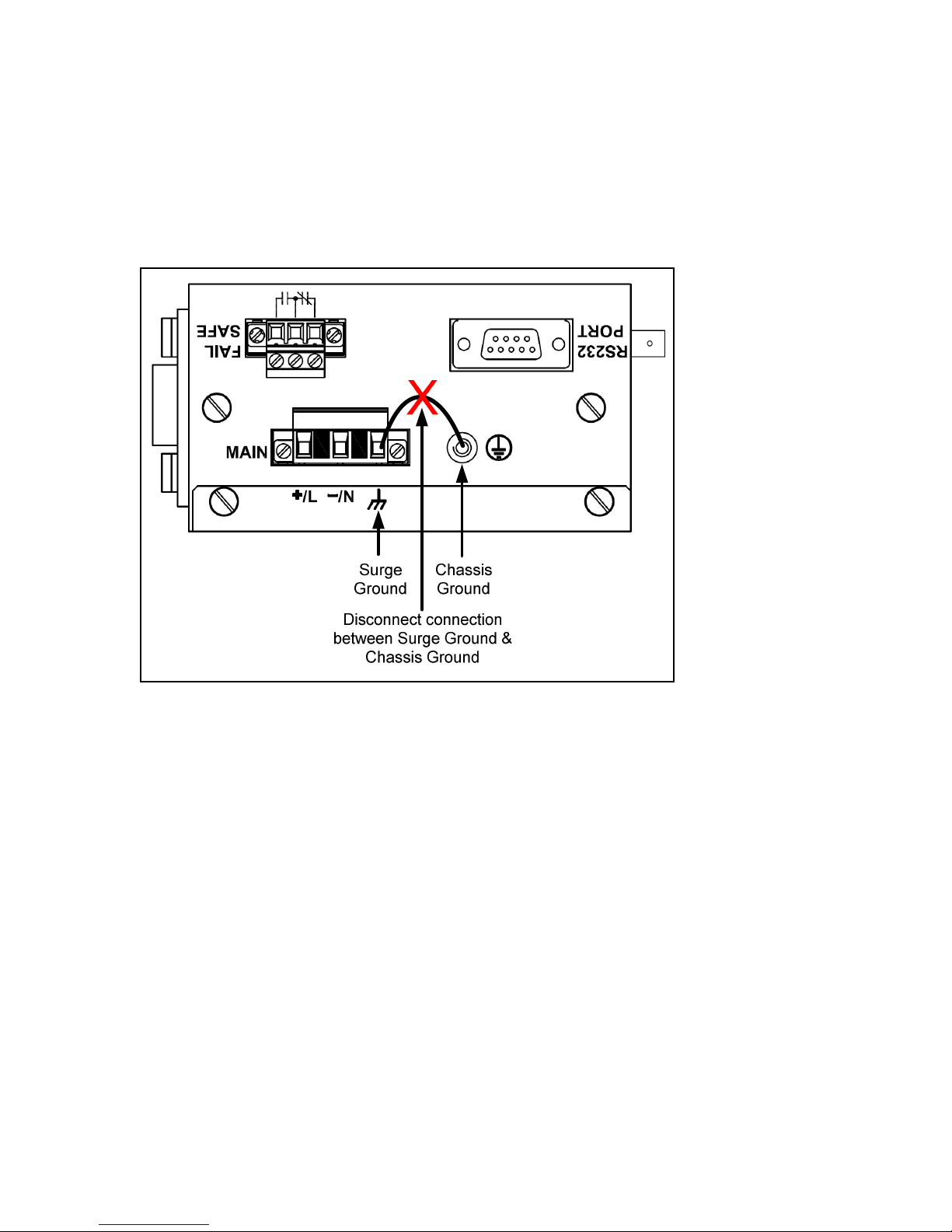
Units which are to have dielectric strength testing (HIPOT testing) done in the field must have the
braided ground cable disconnected during the test. This is required in order to prevent the surge
suppression circuitry, which is connected to surge ground, from being activated.
Figure 6 - Dielectric Strength Testing
Altri manuali per RuggedWireless RS900W Family
3
Indice
Altri manuali RuggedCom Punto di accesso wireless


