Sanyo LCD-32CA8Z Manuale utente

Model No. LCD-32CA8Z
LCD-37CA8Z
LCD-42CA8Z
(Indonesia,Malaysia,Vietnam,Thailand)
Service Ref.No.LCD-32CA8Z-00
LCD-37CA8Z-00
LCD-42CA8Z-00
SERVICE MANUAL LCD Television
Safety Notice................................................2
Specifications...............................................3
Chassis Block Diagrams..............................4
CPU Block Diagrams ..................................5
On-screen Service Menu System................6
Service Adjustments.................................7-8
Mechanical Disassembly........................8-14
Chassis Electrical Parts List.................15-35
Printed Wiring Board.............................36-40
Product Code: 32CA8Z:1-130-109-16
37CA8Z:1-130-110-16
42CA8Z:1-130-111-16
Original Version
Chassis Series:UH2-B
REFERENCE NO. SM3010271N5JV/N5KV/N5LV
Contents
FILE NO.
Give complete "SERVICE REF. NO." for parts
order or servicing.It is shown on the rating lable
at the cabinet back of the unit.
This T.V. receiver will not work properly in
foreign countries where the television
transmission system and power source
differ from the design specifications. Refer
to the specification table.
3&
79$9 :,'(
-/--
TIMER
DVD
PIP POP MAIN/SUB CHANGE
OK
ENTER BACK
MENU
PICTURE
PREV NEXT
BASS
TXT/TV
S.SYS SURROUND
SOUND
STILL

2
Safety Notice
Safety Precautions
The following precautions must be observed.
1:Comply with all caution and safety-related notes provided on the cabinet back, cabinet bottom, inside the
cabinet or on the chassis.
2:When replacing a chassis in the cabinet, always be certain that all the protective devices are installed
properly, such as, control knobs, adjustment covers or shields, barriers, etc..
DO NOT OPERATE THIS TELEVISION WITHOUT THE PROTECTIVE SHIELD IN POSITION AND
PROPERLY SECURED
3:Before replacing the cabinet cover, thoroughly inspect the inside of the cabinet to see that no stray parts or
tools have been left inside.
Before returning any televison to the customer, the service personnel must be sure that it is completely safe
to
operate without danger of electrical shock.
Product Safety Notice
Product safety should be considered when a component replacement is made in any area of a
receiver.
Components indicated by mark
i
in the parts list and the schematic diagram designate components in
which
safety can be of special significance. It is particularly recommended that only parts designated on the parts
list
In this manual be used for component replacement designated by mark . No deviations from
resistance
Wattage or voltage ratings may be made for replacement items designated by mark .

3
Specifications
Maximum Visible Range 32CA8Z:80cm ;37CA8Z:94cm ;42CA8Z:107cm (Screen Diagonal Size)
Picture Resolution: WXGA 1366(H) x 768(V)
Viewable Angle(Lە/3) L/R ± 89D, U/D ± 89D
Brightness ≥500cd/m²
Contrast LCD-32/37CA8Z: 1200:1 ; LCD-42CA8Z : 1500:1
Definition RF Analog Signals: Horizontal≥350; Vertical≥400
Degree of Color Coverage ≥32%
Mobile Trailer Time ≤20ms
Voltage and Power Consumption
AC100-242V 50/60Hz
32CA8Z:140W; 37CA8Z:158W; 42CA8Z:241W
Power Management VESA DPMS
Colour System PAL/NTSC/NTSC4.43/SECAM
Sound System D/K,I,M,B/G
Channel Coverage VHF:21 ~ 69, A14 ~ A69, J13 ~ J62
UHF:E2 ~ E12, R1 ~ R12, K1 ~ K9, J1 ~ J12, A2 ~ A13
CATV:S1 ~ S14, X, Y, Z, Z+1, Z+2
Aerial input impedance 75Ω
Speaker Size 6cm x 12cm x 2pcs
Sound speciality Left and Right audio input : Maximum Input Power is 9W
Total Harmonic Distortion(THD)≤10%
Input terminals PC terminal:RGB X 1
HDMI terminal:x1
Audio:Mini stereo jack x 1 (Audio input of PC)
Video:Composite video terminals x2(1Vp-p,75Ω)
*AV2 Video input is combined with component Y input.
S-VIDEO input: DIN 4-pin Jack x1
DVD input: Component Y, CB/PB, CR/PR input x 1
Audio input: (R/L)x 4
Output terminals Video Monitor Output: RCA jack x 1
Audio Monitor Output: L/R Stereo Output (RCA jack) x 1 set
Headphone Jack : Mini stereo jack x1
Dimensions(Width x Height x Depth)
LCD-32CA8Z: 819mm X 624mm X 271mm(Including Stand)
LCD-37CA8Z: 935mm X 695mm X 271mm(Including Stand)
LCD-42CA8Z: 1049mm X 758mm X 271mm(Including Stand)
Net Weight(Including Stand)
LCD-32CA8Z: <14.5KG LCD-37CA8Z: <19.6KG LCD-42CA8Z: <25.4KG
Operating Entironment
Operating Temperature 0ºC~40ºC(32ºF~104ºF)
Operating Humidity 20~80%
Storage Temperature -10ºC~50ºC(14ºF~122ºF)
Storage Humidity 20~80%
4
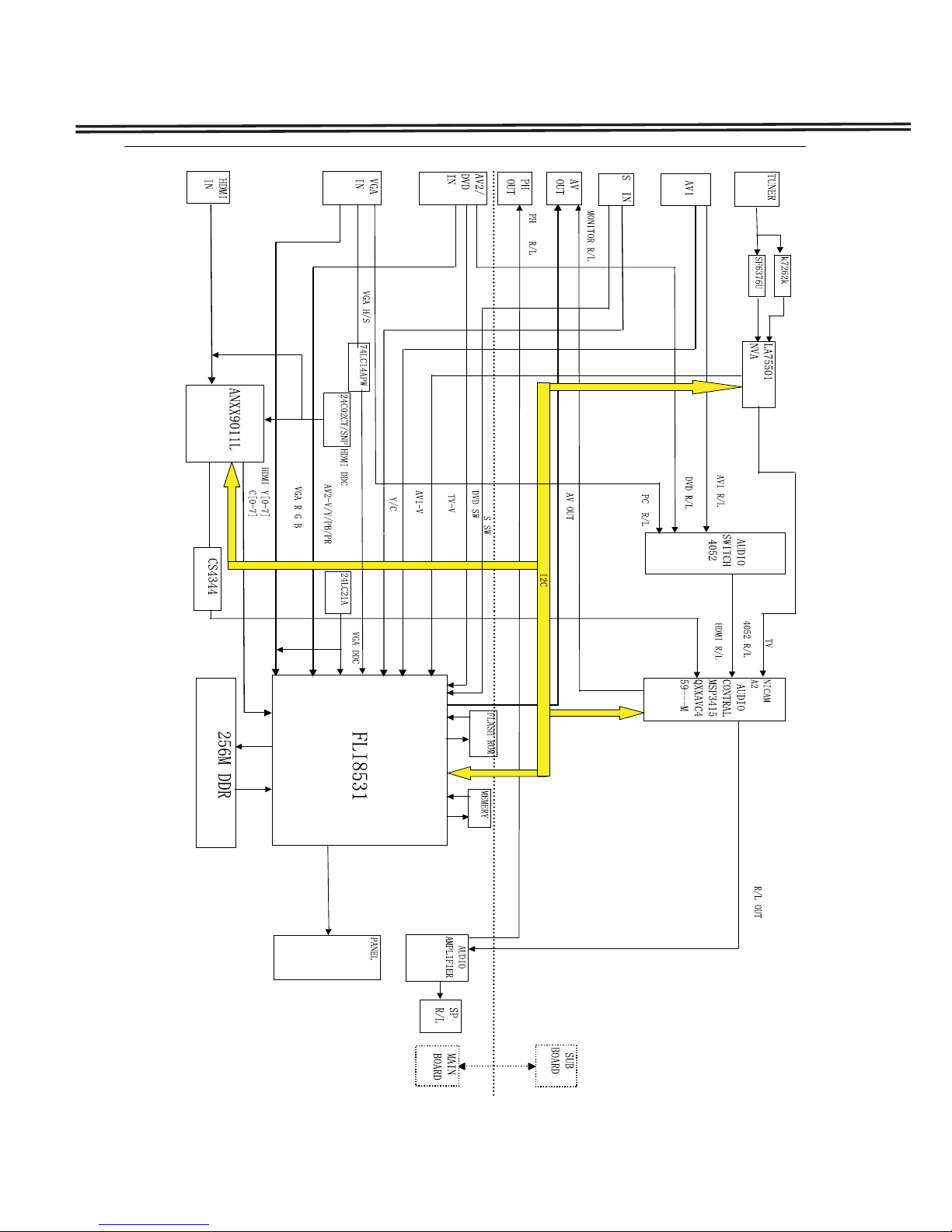
Chassis Block Diagrams
5
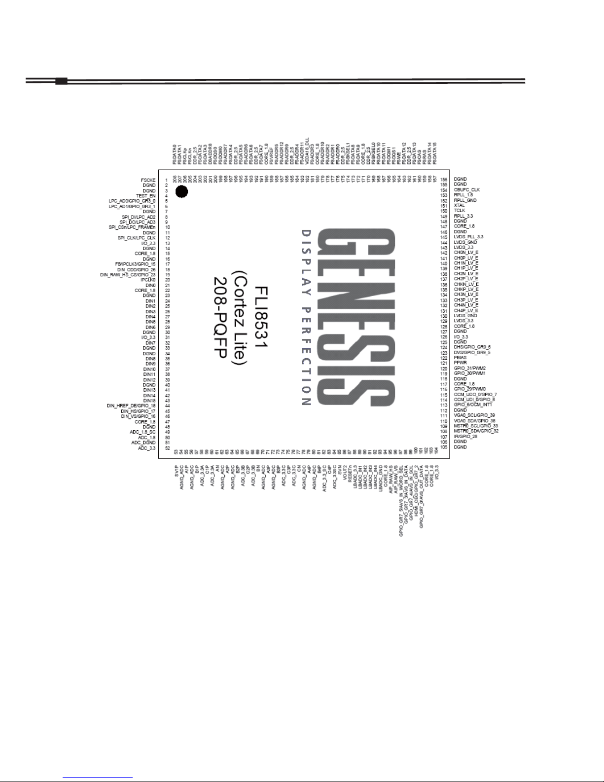
IC7200 QFLI8531-AB-M (FLI8531-ABM)
CPU Block Diagrams

6
On-screen Service Menu System
On-screen Service Menu System
1) How to enter the Service Menu
1. Press MENU button on SIDE controls, MENU will display.
2. Press and hold MUNE button on SIDE controls and press “1” button on remote controls. SERVICE
MENU will display.
General
This set has an On-screen Menu system included in the CPU that allows remote operation for most of the
service adjustments.
TIMER
DVD
"1"button
Remote controls
MUNE button
SIDE controls
2) How to select the service section and service item and change data value:
To select service section: Press the Cursor ▲or ▼button on the remote control hand set, and press the OK
button to enter the SUB menu.
To change data value: Select service item by pressing the Cursor ▲or ▼button , and change data value by
pressing the Cursor ◄or ►button.
3) Exit from the service menu
Press the MENU button repeatedly or turn off the TV set by pressing the POWER ON/OFF button.
7
How to adjust White Balance Adjustment
1. Input a white pattern(80%) to the composite input terminal.
2. Set the television to following conditions:
Picture mode: standard
Colour temperature: normal
Pre-heading time: more than 10 minutes
3. Enter the service mode, and select item 291with ▲or ▼key.
Select RGB with ▲or ▼key.
Press ◄► to adjust the value of RGB until the white balance R, G,B is all 85h.
3. After adjustment, confirm white balance again by normal picture.
ADC Adjustment
Note:
Because White Balance Adjustment will be changed when adjusting ADC. After adjusting ADC, please reset
White Balance Adjustment.
How to adjust ADC
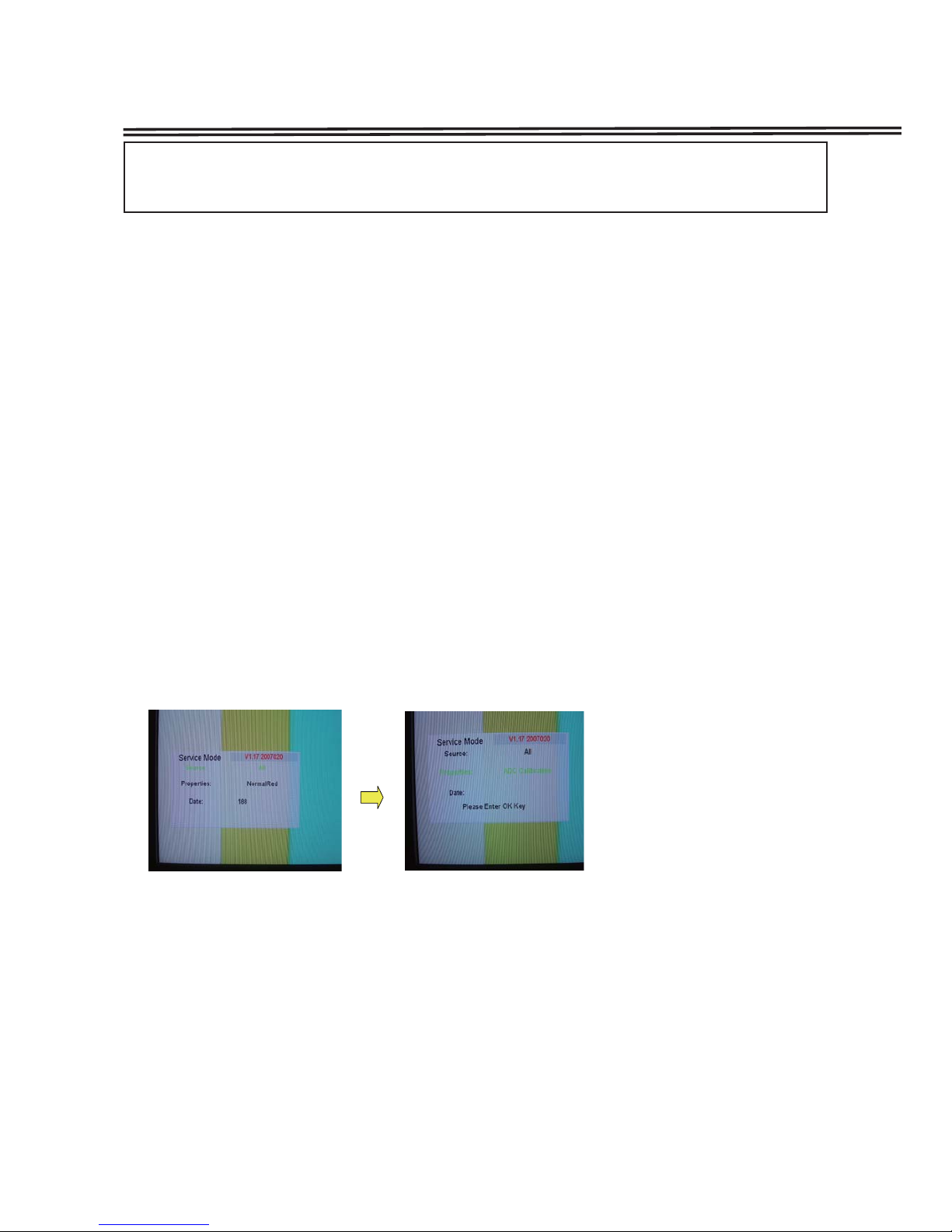
1.Recive 100% COLOUR BAR from AV1.
2. Enter to SERVICE MODE.
3. Remove the cursor from [Source] to [Properties]. And then select "ADC Calibration", press OK button.
4. Wait for about 15 seconds until the adjustment is finished. Then press MENU button to exit.
Service Adjustments
Important Notice:
Do not attempt to adjust service adjustments not listed below otherwise it may cause loss of performance
and for correct operation.
White Balance Adjustment

8
Service Adjustments
VCO Adjustment
How to adjust VCO
1. Receive PAL color bar pattern.(ANT input level:58dbuv 75ohms terminated)
2. Connect a digital volt meter to VCO level terminal(TP-VCO) and the ground.
3. Adjust T202, until the volt is 3.6±0.2v DC.
AGC Adjustment
How to adjust AGC
1. Receive PAL color bar pattern.(ANT input level:58dbuv 75ohms terminated)
2. Connect a digital volt meter to tuner-AGC terminal(TP-A) and the ground.
3. Adjust the variable resistance VR202, until the volt is 3.2±0.2v DC.
(一)Cabinet Back Removal
1.Remove screws A,B.
2.Take the Cabinet Back off.
(A:16pcs,B:4pcs)
A
A
A
A
A
A
AA A A图1
AA
AA
AA
B
Mechanical Disassembly(LCD-42CA8Z)

9
Mechanical Disassembly(LCD-42CA8Z)
Power board
LCD SCREEM
KEY&LED
BOARDS
main
board
SUB
board
(二)Chassis and Terminal Board Removal
1. Remove screws C , D and F, take the terminal board off.
2. Remove Screw E,take P Board off.
(C: 1pcs, D: 2pcs, E:15pcs, F:2pcs)
DC
F

10
Mechanical Disassembly(LCD-42CA8Z)
E
E
E
(一)Cabinet Back Removal
1.Remove screws A,B.
2.Take the Cabinet Back off.
(A:12pcs,B:6pcs)
Mechanical Disassembly(LCD-37CA8Z)
A
A
A
A
A
A
A
B
AA
AA
A
Altri manuali per LCD-32CA8Z
1
Questo manuale è adatto per i seguenti modelli
5
Indice
Altri manuali Sanyo Altro


