Seat C 2SP Manuale utente

Type C 2SP remote
controller
REF 819756/819757
The type C 2-speed remote controller is a safety device for controlling air flow regulation
at low and high speed depending on the position of the sash.
A speed sensor is used to determine the flow rate. Audible and visual alarm is set off in
case of insufficient speed or too high sash height and other malfunctions. The controller
engages the second gear by means of a contactor placed in the path of the sash.
The remote HMI is used to control the fume cupboard ventilation and to carry out the
following adjustments on site.
This controller complies with EN 14175 and RoHS Standards.

2
Table of contents
1. Presentation .................................................................................................................................... 3
1.1. HMI (Human Machine Interface) ................................................................................................ 3
1.2. CPU (Central Processing Unit) ..................................................................................................... 3
1.3. Schematic diagram ...................................................................................................................... 4
1.4. Connector specifications ............................................................................................................. 5
2. Installation and mounting ............................................................................................................... 6
2.1. Dimensions.................................................................................................................................. 6
2.2. Positioning on the fume hood..................................................................................................... 7
2.3. Cutting template ......................................................................................................................... 8
2.4. Installation tips............................................................................................................................ 9
3. Wiring diagram.............................................................................................................................. 10
4. Adjustment procedure .................................................................................................................. 11
5. Factory rest.................................................................................................................................... 13
6. Test mode...................................................................................................................................... 13
7. Change the audible alarm delay.................................................................................................... 14
8. Error messages (digital display option) ......................................................................................... 14
9. FAQ................................................................................................................................................ 14
10. Maintenance.............................................................................................................................. 15
11. Warranty.................................................................................................................................... 15
02/11/2021

3
1. Presentation
The remote type C 2SP remote controller consists of a small HMI, easily installed on a fume
hood, and a central processor.
1.1. HMI (Human Machine Interface)
1.2. CPU (Central Processing Unit)
Display
(Option)
Green LED: air flow OK
Red LED: insufficient air flow
Orange LED: Sash too high
Yellow LED: Ventilation ON/OFF
Push button: ON/OFF ventilation
Yellow LED: Lighting ON/OFF
Push button: ON/OFF lighting
Orange LED: auxiliary faults
Push button: stop buzzer
VENT1 : ON/OFF
ventilation relay
VENT2 : ON/OFF
ventilation relay
Alarm contact
Light relay
Overtaking sash
contact
Second velocity
switch
Output 0/10V
Transformer 230v/12v
connector
Speed probe
connector
Push-button
velocity display
Cut the resistance to activate
the night setback mode
Remote HMI
connector
4
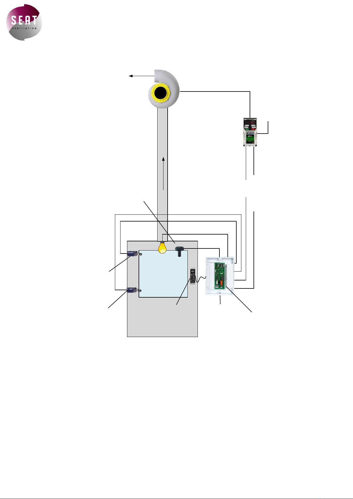
1.3. Schematic diagram
220v power
supply
FAN1 ON/OFF
0/10V
220v
power
supply
Switch sash
position
Velocity probe
Deported HMI CPU box
Second
velocity switch
The remote type C 2-speed controller is used to control the airflow of a fume hood.
Pressing the ventilation ON/OFF button on the remote HMI closes the two relays VENT 1 and 2, which
unlocks the drive. The controller then sends a 0/10v signal that the drive will interpret in order to change
the motor rotation speed and the flow rate. This is a two-speed controller: the CPU sends a fixed voltage
when the sash is low and another fixed voltage when it is high.
A speed sensor permits to measure whether the suction flow is sufficient (≥0.4 m/s) and indicates the
ventilation status by a green and red LED.
The front panel allows you to control the operation of the fume hood and in particular:
-An ON/OFF for lighting
-An ON/OFF for ventilation
-An alarm stop button

5
1.4. Connector specifications
Power supply
Electrical transformer 230v/12v 500mA. (delivered with)
VENT1/FAN1
ON/OFF Ventilation relay driving by
Disconnection voltage: 120v
Disconnection current: 0.5 A
VENT2/FAN2
Same VENT1
0/10v
0/10v output which returns a voltage according to the speed
measured by the sensor. This output must be sent to the
frequency inverter.
a
LIGHT
ON/OFF lighting relay driving by
Disconnection voltage: 220v
Disconnection current: 3 A
ALARM
Relay controlled by alarm activation. Normally open contact
Disconnection voltage: 120v
Disconnection current: 0.5 A
SASH Open
Sash contact which triggers a visual and audible alarm.
IDLE
Sash Contact which toggles from low speed to high speed.

6
2. Installation and mounting
2.1. Dimensions
HMI
CPU
Speed sensor
65 mm
40 mm
28 mm
22 mm
7
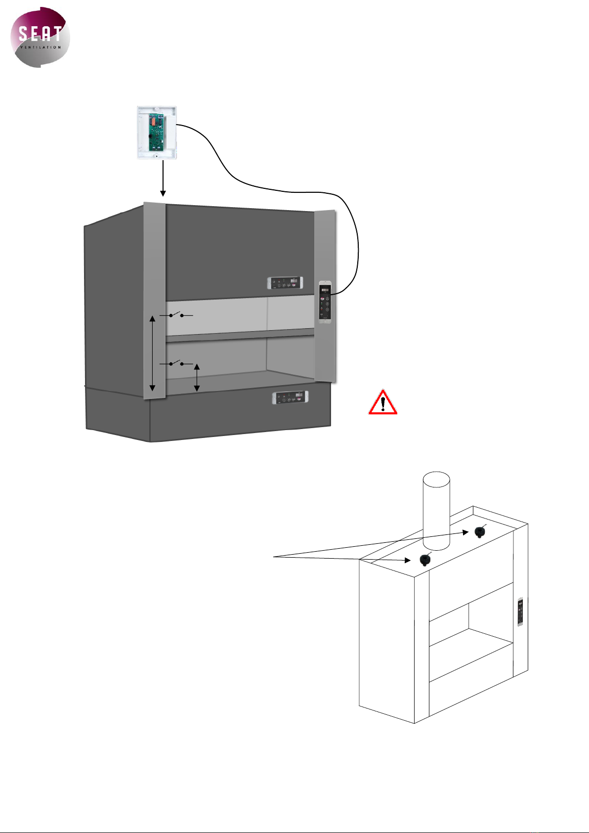
2.2. Positioning on the fume hood
The speed sensor must be positioned on
the fume hood ceiling in one of the two
positions shown in the diagram.
These locations must be respected so that
the probe is accurate.
Drill a 22mm diameter hole and put the
speed sensor in it.
An adhesive is provided on the sensor to
fix it correctly to the fume hood and
prevent leaks.
Where to install the speed sensor?
500mm
150 mm
Vertical HMI are usually attached to
the side frame of fume hoods.
Horizontal HMI’s can be set at the
user’s convenience.
◌
To comply with EN 14175
standard, you must install a
sash contact.
The sash contact must be fixed so that
it sets off when the sash exceeds
400mm or 500mm.
◌
The 2nd gear contact is installed
approximately 150mm above the work
surface.
◌
You can install the CPU
in the false ceiling of
the fume cupboard.
The controller is delivered with
a 2,5 meters cable.

8
2.3. Cutting template
If you want to install your fume hood controller without the surface bow mounting, you will
need to make the following cuts:
31mm
110mm

9
2.4. Installation tips
•Do not install the sensor on the extraction tube above the fume hood
•Avoid installing the sensor in a dead zone of the fume cupboard
•The probe must pass entirely through the fume cupboard ceiling. Otherwise, you
must use a 25mm PVC tube to extend the outlet.
•A speed of 0.2 m/s minimum must be measured through the sensor to ensure proper
operation.
•When adjusting the controllers, it is necessary that:
oThe fans are running
oThe laboratory is completely closed (doors, windows, etc.)
oHave an anemometer
•Pay attention to motor connections (star or delta)
230V single phase
power supply
400V three phases
power supply
400V three phases
output
230V three phases
output
DELTA
STAR

10
3. Wiring diagram
220v power
supply
220v power
supply
0/10V
ON/OFF
ventilation
Switch sash
position
Second velocity
switch
Switch sash position
2nd speed switch
Questo manuale è adatto per i seguenti modelli
2
Indice
Altri manuali Seat Telecomando


