Remote control LT5
Intruder alarm system Installation manual
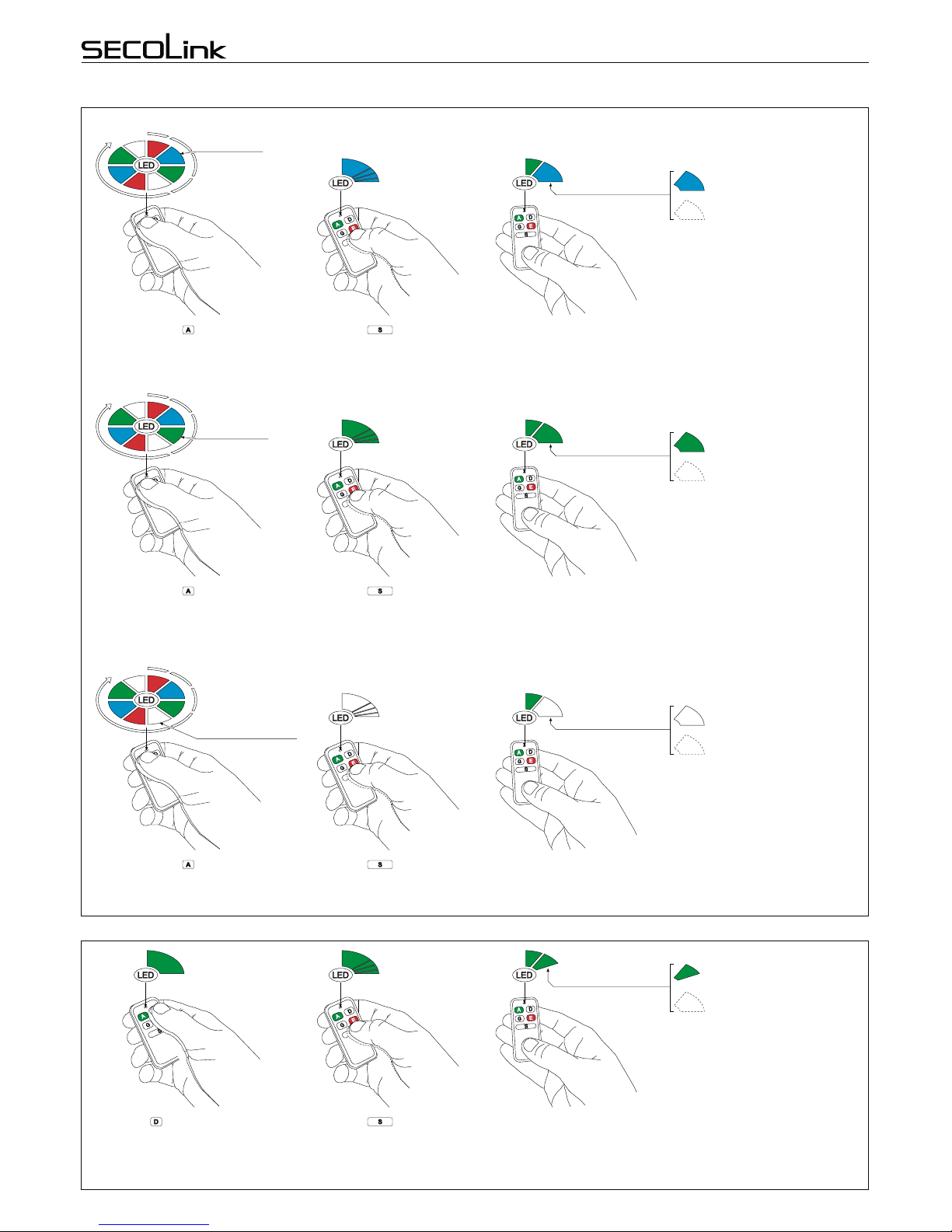
STATUS INQUIRY
ALARM CLEARING WITH BUTTON (SINGLE PRESS OPERATION)
TRIGGERING A PANIC ALARM WITH BUTTON. COMMAND SENDING BY PRESSING THE BUTTON
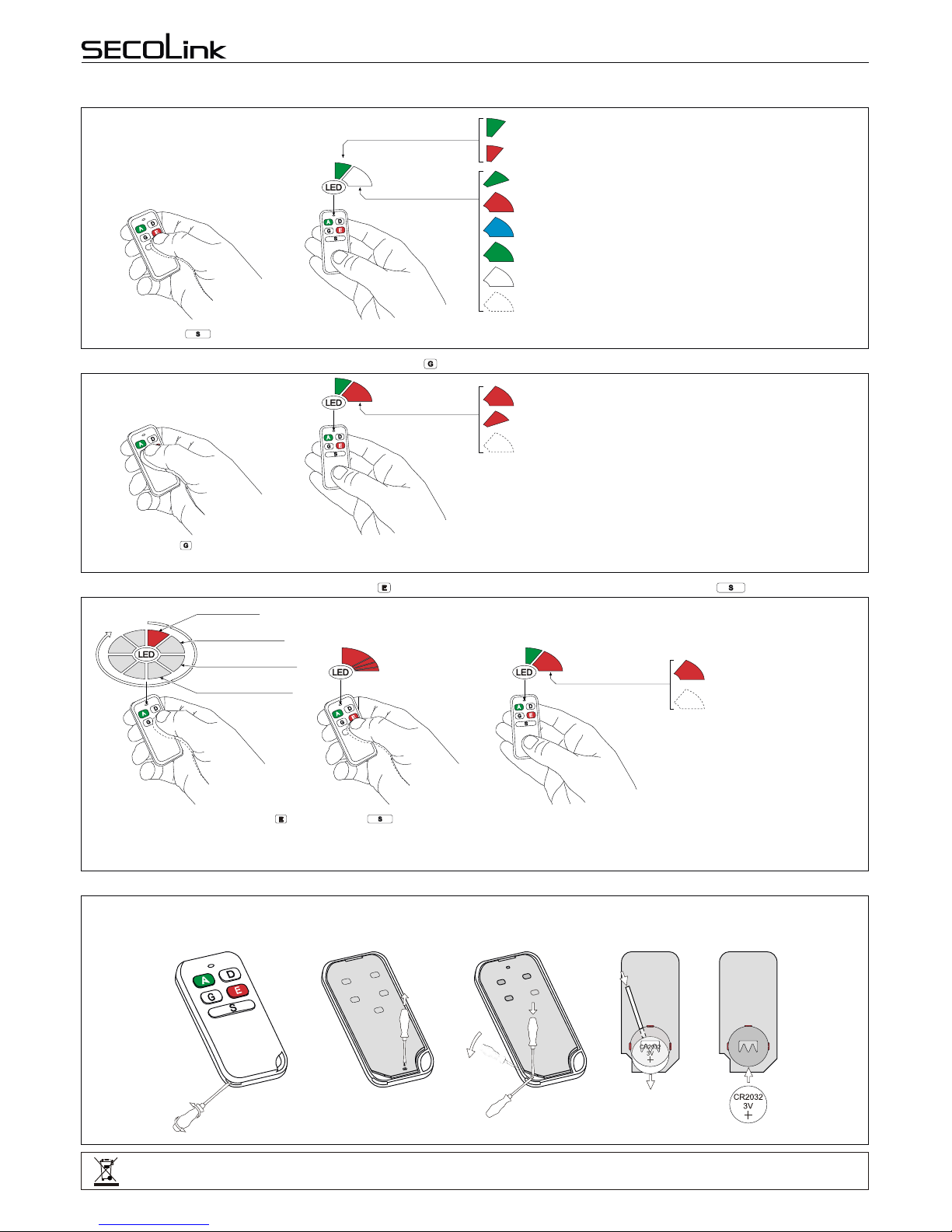
BATTERY REPLACEMENT
The answer from the system depends on system status (see picture).
Press the button.
GR
Red (short) = PGM output is turned Off
Red (long) = command is executed or PGM output is turned on
No flash = No answer from the system!
B
R
R
If the command is executed or PGM output is turned On, the answer from the system will be a long lasting Red
color flash. If the PGM output is turned Off, the answer from the system will be a short lasting Red color flash.
Green(short:~0,1sec)=batteryisgood
Red(short)=batteryislow
Answer from the
system
G?
G
R
Command sending and
battery status indication
Green (short: ~0,1 sec) = system is disarmed
Red (long: ~1 sec) = system is armed in Away mode
Blue (long) = system is armed in Night mode
Green (long) = system is armed in Stay mode
White (long) = system is armed in Max Away mode
No flash = No answer from the system!
B
R
G
W
G
Press the button while the
Red color light is visible on LED
and wait for the system to answer.
Only one command is assigned to
button in factory template. This is the
reason why only the Red color light will
be visible on LED.
If the panic alarm is succesfully triggered the answer from the system
will be a long lasting Red color flash on LED.
RRed (long) = panic alarm is
triggered
No flash = no answer from the
system!
Answer from the
system
GRR
Red =Panic
Green = Not Used
Blue = Not Used
White = Not Used
RB
G
WR
B
GW
Please act according to local laws. Don't throw away unusable alarm systems or its components along with household waste. This product’s
utilizationinEUstatesisregulatedbyEUdirective2002/96/EC
Remotecontrolunit’sbatterylifedependsontheenvironment,usage,andthespecificwirelessdevicesbeingused.Humidity,highorlowtemperatures,and
large swings in temperaturesmay all reduce the actual battery life.Remote control until will warn you about its discharged battery on LED. It will show the
batterystatusonLEDatatimewhenacommandwillbesenttoareceiver.
BATTERY REPLACEMENT
Insert the blade of a small
screwdriver between the remote
control unit plastic top and bottom
cover and slightly turn it.
Remove the screw that is holding
the electronic circuit board in place. Insert the blade of a small
screwdriver in place as it is shown in
picture and carefully remove the
electronic circuit board from plastic
housing.
Use an isolated stick and remove the old battery.
With a positive (+) end of a new battery facing UP,
insert the new battery as shown in picture.
New battery
2
1
Remote control LT5
Intruder alarm system Installation manual
STATUS INQUIRY
ALARM CLEARING WITH BUTTON (SINGLE PRESS OPERATION)
TRIGGERING A PANIC ALARM WITH BUTTON. COMMAND SENDING BY PRESSING THE BUTTON
BATTERY REPLACEMENT
The answer from the system depends on system status (see picture).
Press the button.
GR
Red (short) = PGM output is turned Off
Red (long) = command is executed or PGM output is turned on
No flash = No answer from the system!
B
R
R
If the command is executed or PGM output is turned On, the answer from the system will be a long lasting Red
color flash. If the PGM output is turned Off, the answer from the system will be a short lasting Red color flash.
Green(short:~0,1sec)=batteryisgood
Red(short)=batteryislow
Answer from the
system
G?
G
R
Command sending and
battery status indication
Green (short: ~0,1 sec) = system is disarmed
Red (long: ~1 sec) = system is armed in Away mode
Blue (long) = system is armed in Night mode
Green (long) = system is armed in Stay mode
White (long) = system is armed in Max Away mode
No flash = No answer from the system!
B
R
G
W
G
Press the button while the
Red color light is visible on LED
and wait for the system to answer.
Only one command is assigned to
button in factory template. This is the
reason why only the Red color light will
be visible on LED.
If the panic alarm is succesfully triggered the answer from the system
will be a long lasting Red color flash on LED.
RRed (long) = panic alarm is
triggered
No flash = no answer from the
system!
Answer from the
system
GRR
Red =Panic
Green = Not Used
Blue = Not Used
White = Not Used
RB
G
WR
B
GW
Please act according to local laws. Don't throw away unusable alarm systems or its components along with household waste. This product’s
utilizationinEUstatesisregulatedbyEUdirective2002/96/EC
Remotecontrolunit’sbatterylifedependsontheenvironment,usage,andthespecificwirelessdevicesbeingused.Humidity,highorlowtemperatures,and
large swings in temperaturesmay all reduce the actual battery life.Remote control until will warn you about its discharged battery on LED. It will show the
batterystatusonLEDatatimewhenacommandwillbesenttoareceiver.
BATTERY REPLACEMENT
Insert the blade of a small
screwdriver between the remote
control unit plastic top and bottom
cover and slightly turn it.
Remove the screw that is holding
the electronic circuit board in place. Insert the blade of a small
screwdriver in place as it is shown in
picture and carefully remove the
electronic circuit board from plastic
housing.
Use an isolated stick and remove the old battery.
With a positive (+) end of a new battery facing UP,
insert the new battery as shown in picture.
New battery
2
1
Old battery
Press the button.
Page 3
Rev.12/09/16_KF