Sel D1000 Manuale utente

SELCO A/S D1000 Manual
Revision: 29-07-2011 Page 1
D1000 Arc Detection Relay
Manual

SELCO A/S D1000 Manual
Revision: 29-07-2011 Page 2
Contents
1Introduction..................................................................................................................................4
2Installation ...................................................................................................................................5
3Power Supply...............................................................................................................................6
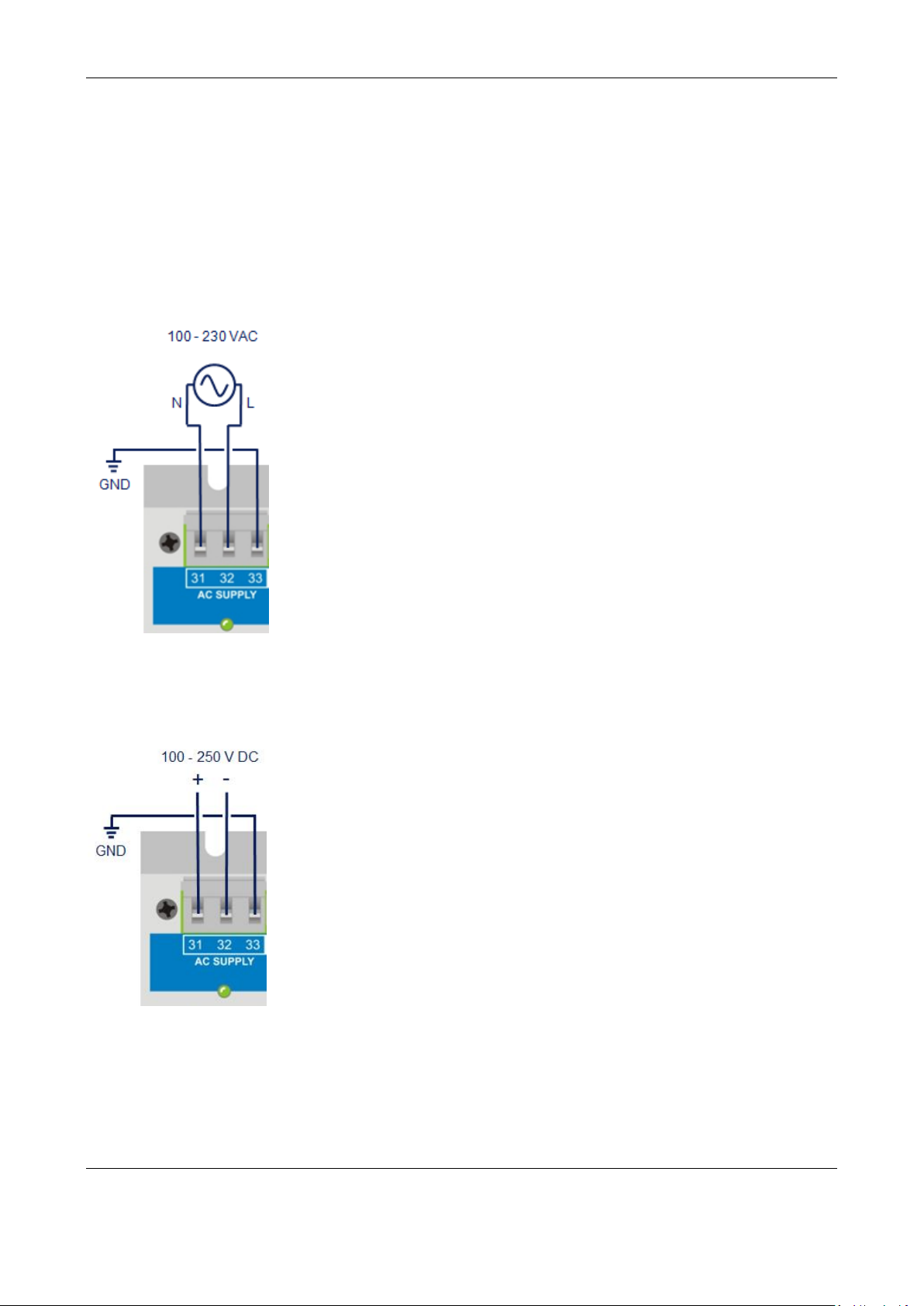
3.1 AC Supply 100 V to 230 V......................................................................................................6
3.2 DC Supply 100 V to 250 V......................................................................................................6
3.3 DC Supply 12 V to 48 V..........................................................................................................7
3.4 Battery Supply 24 V.................................................................................................................7
4Link..............................................................................................................................................8
4.1 Link interface...........................................................................................................................8
4.2 Link configuration ...................................................................................................................8
4.3 Button function ........................................................................................................................8
5Sensor Inputs ...............................................................................................................................9
5.1 Photoelectric point sensors with cable monitoring................................................................10
5.1.1 Connection of point sensors:..............................................................................................10
5.1.2 Installation of point sensors in the switchboard.................................................................11
5.2 A2000 fibre sensor with cable monitoring.............................................................................11
5.2.1 Fibre...................................................................................................................................12
5.2.2 Receiver .............................................................................................................................13
5.2.3 Transmitter.........................................................................................................................13
5.2.4 Sensor adjustment according to fiber length......................................................................14
5.2.5 Sensor adjustment in small compartments.........................................................................14
5.3 A0200 and A0300 point sensors without cable monitoring...................................................15
6Placement of sensors..................................................................................................................16
6.1 Switchboard Protection..........................................................................................................16
6.2 Transformer Protection..........................................................................................................17
7Current Sensor ...........................................................................................................................18
8Auxiliary Inputs.........................................................................................................................19
8.1 Inhibit.....................................................................................................................................19
8.2 Trip.........................................................................................................................................19
8.3 Reset.......................................................................................................................................19
9Outputs.......................................................................................................................................20
9.1 Online.....................................................................................................................................20
9.2 Service....................................................................................................................................20
9.3 Tripped...................................................................................................................................20
9.4 Trip Coil output......................................................................................................................21

SELCO A/S D1000 Manual
Revision: 29-07-2011 Page 3
10 D1000 LEDs..............................................................................................................................22
11 D1000 buttons............................................................................................................................25
11.1 Mode......................................................................................................................................25
11.2 Trip.........................................................................................................................................25
11.3 Reset.......................................................................................................................................25
11.4 Mode +Trip............................................................................................................................25
12 Configuration.............................................................................................................................26
12.1 Connecting to the PC .............................................................................................................27
12.2 Description of the configuration tool.....................................................................................28
12.3 General description of buttons in the configuration tool .......................................................29
12.3.1 Revert.............................................................................................................................29
12.3.2 Reset...............................................................................................................................29
12.3.3 Save all...........................................................................................................................29
12.3.4 Reset page......................................................................................................................29
12.3.5 Revert page ....................................................................................................................29
12.4 General Parameters:...............................................................................................................30
12.5 Configuration of light sensors................................................................................................31
12.5.1 Common delays and limits.............................................................................................31
12.5.2 Sensor 1..........................................................................................................................32
12.5.3 Front panel sensor..........................................................................................................32
12.6 Configuration of current sensor .............................................................................................33
12.6.1 Setup ..............................................................................................................................33
12.7 Configuration of digital inputs...............................................................................................36
12.7.1 Inhibit input...................................................................................................................36
12.7.2 Trip input .......................................................................................................................37
12.7.3 Reset input .....................................................................................................................38
12.8 Configuration of trip output...................................................................................................39
12.9 Advanced settings..................................................................................................................40
12.10 About..................................................................................................................................40
13 Event logging.............................................................................................................................41
14 Commissioning..........................................................................................................................42
14.1 Configuration of installed sensors .........................................................................................42
14.2 Testing the sensors.................................................................................................................43
14.3 Testing the trip coil................................................................................................................43
14.4 Full operation Test (online) ...................................................................................................44
14.5 Adjustment of Sensor Sensitivity..........................................................................................44
15 Specifications.............................................................................................................................45

SELCO A/S D1000 Manual
Revision: 29-07-2011 Page 4
1Introduction
The D1000 Arc detection relay is a stand-alone, high speed arc protection unit for electrical power
distribution systems. The D1000 supports both point and fibre sensor technologies for optical arc
detection. The D1000 has inputs for up to six sensors and the sensors can be combined depending
on the application and requirements.
In case of an arc fault, the D1000 detects and generates a tripping pulse in less than 1 millisecond.
The tripping pulse is typically used to trip the circuit breaker(s) supplying the installation. The total
arcing time is thus reduced to the mechanical opening time of the circuit breaker, which are
approximately 50 to 75 milliseconds. The trip circuit is based on a solid state switch (IGBT), which
provides fast reaction and sufficient drive capability for even the largest circuit breakers.
The D1000 can be powered from either a DC or AC source. If the D1000 is powered from AC, it
can charge a backup battery, which can drive the trip circuit by 24 V DC.
Built-in over current protection
The D1000 integrates 3-phase current measurements for detection of short circuit and over current
with a reaction time of approximately 1 millisecond. This makes it possible to reduce unintended
tripping from external light sources, e.g. lightning or welding flashes without the extra delay and
expense of an external over current relay. The over current function can also be used to trip the
breaker in case of short circuits or long-lasting overloads without arcing.
Efficient self-supervision
The D1000 provides continuous surveillance of the complete system including the connected
sensors. Any system faults, e.g. a sensor cable fault is indicated by a flashing online LED and is
logged and reported.
Real-time event logging
The built-in USB connection provides easy access to a real-time event log, which provides detailed
diagnostic information on all events, including near misses and events related to daily operation
(e.g. configuration changes, test, reset, and power cycling).
Extended coverage with the Link Input
In order to form a larger protection system the D1000 is easily expandable. With the Link Input, up
to 4 D1000 units can be connected together, giving a total of 24 sensor inputs. Alternatively, the
link feature can be used for RS485 MODBUS RTU communication (SCADA), and thereby easily
integrate into an external monitoring and control system.

SELCO A/S D1000 Manual
Revision: 29-07-2011 Page 5
2Installation
The D1000 is secured to the rear of the switch board using four 5 mm screws or alternatively DIN
rail mounting. In case DIN rail mounting is intended, mounting brackets can be purchased
separately from SELCO.
Please ensure that enough space is given around the module so that the plug-in terminals can be
removed and re-inserted. The length of the cables should also allow for the easy removal and
insertion of the plug-in terminals.

SELCO A/S D1000 Manual
Revision: 29-07-2011 Page 6
3Power Supply
The D1000 Arc Detecting Relay can be supplied by AC or DC.
3.1 AC Supply 100 V to 230 V
Terminals 31 and 32 are used for the AC supply. The supply voltage must be between 85 to 265 V
(rated voltages from 100 V-15% to 230 V+15%).
3.2 DC Supply 100 V to 250 V
Alternatively terminals 31 and 32 can be used for the DC supply. The supply voltage must be
between 85 to 300 V (rated voltages from 100 V-15% to 250 V+20%).

SELCO A/S D1000 Manual
Revision: 29-07-2011 Page 7
3.3 DC Supply 12 V to 48 V
Terminals 34 and 36 can be used for the DC supply. The supply voltage must be between 8 V to 60
V (rated voltages from 12 V-30%to 48 V+25%).
3.4 Battery Supply 24 V
Terminals 35 and 36 can be used for DC supply by battery. The battery (Gel Cell) voltage is 24 V
DC.
Note: The D1000 includes a battery charger that will maintain the battery fully charged as
long as there is voltage on the power supply terminals 31 and 32 (regardless if this is AC or
DC). The power supply on terminals 34 and 36 cannot charge the battery.
In case the D1000 is charged by battery only and the battery voltage drops below 20 V, the D1000
will shut down in order to protect the battery. Arc monitoring is then suspended.

SELCO A/S D1000 Manual
Revision: 29-07-2011 Page 8
4Link
The D1000 Link function supports up to 4 D1000 modules that together form one system.
The Link function enables D1000 to share sensors inputs and relay outputs as if they were one unit.
In case of an arc trip, all trip outputs of all connected D1000 modules will trip.
For the Link function to work it is necessary to configure this in the configuration tool.
4.1 Link interface
D1000 link function is programmed by selecting Link interface in the drop down menu.
4.2 Link configuration
Each D1000 must have a unique link address. The lowest address must always be 1.
The D1000 link function continuously monitors cable break faults and therefore it is required to
program the number of D1000 that are connected to the link lines.
Link terminal connections.
-Terminal 37 Link A
-Terminal 38 Link B
4.3 Button function
When the D1000 is
configured for link the front
buttons are considered linked.
Therefore if one D1000 is set
in service mode all the linked
modules are in service mode.
This also applies to the reset
button.
The Trip button will only
work locally, meaning that if
the trip button is activated in
service mode the selected
D1000 will be the only unit
that trips.

SELCO A/S D1000 Manual
Revision: 29-07-2011 Page 9
5Sensor Inputs
6 sensor inputs for light sensitive sensors are available. Four different sensor types at supported:
A1000 Photoelectric point sensors with cable monitoring
A2000 fibre optic sensors with cable monitoring
A0200 / A0300 Photoelectric point sensors without cable monitoring
Connection of the various types of sensors is explained in paragraph 4.1.1 for SENSOR 1 input
(terminals 1 –4). All other sensor inputs can be connected in the same way.
A1000 photoelectric point sensor A2000 fibre optic sensors with cable
monitoring with cable monitoring
A0200 / A0300 photoelectric point sensors without cable monitoring

SELCO A/S D1000 Manual
Revision: 29-07-2011 Page 10
5.1 Photoelectric point sensors with cable monitoring
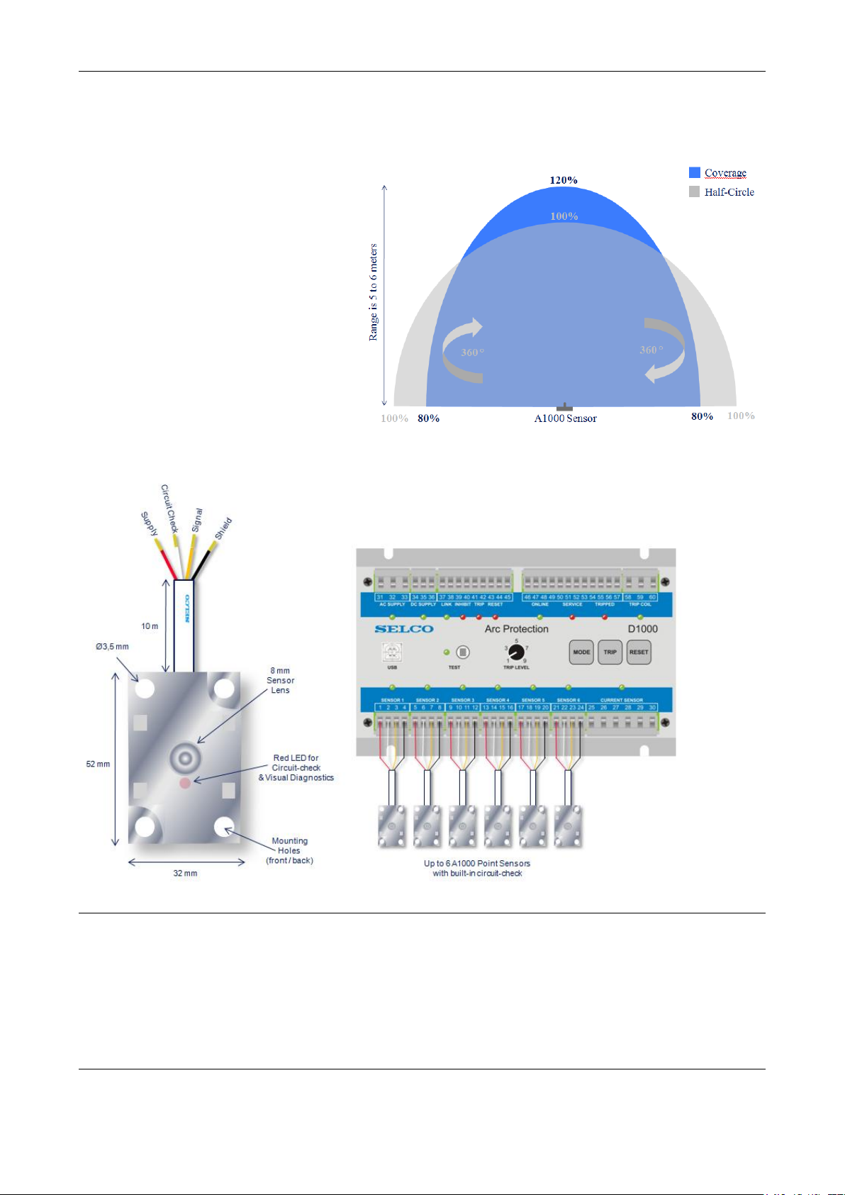
This sensor has a sensitive area of 180°.
The sensor signal is a mA current
signal. The sensor is factory calibrated
to 0.5 mA / klux.
The cable monitoring works via a built
in LED that is fired once every second.
In case the sensor does not detect the
light of the circuit check LED, the
sensor fail alarm is triggered.
5.1.1 Connection of point sensors:
Terminal Function Colour
Terminal 1 Supply Red
Terminal 2 Circuit Check White
Terminal 3 Signal Yellow
Terminal 4 Shield Black / Copper
Questo manuale è adatto per i seguenti modelli
1
Indice
Altri manuali Sel Staffetta

Sel
Sel SEL-300 Series Guida utente

Sel
Sel SEL-487E-5 Manuale utente

Sel
Sel SEL-421-4 Manuale utente

Sel
Sel SEL-487E-3 Manuale utente

Sel
Sel SEL-2664S Manuale utente

Sel
Sel SEL-751 Manuale utente

Sel
Sel 411L Manuale utente

Sel
Sel SEL-421 Manuale utente

Sel
Sel SEL-787 Manuale utente

Sel
Sel SEL-751A Manuale utente