
Servomex AquaXact 1688 Manuale utente
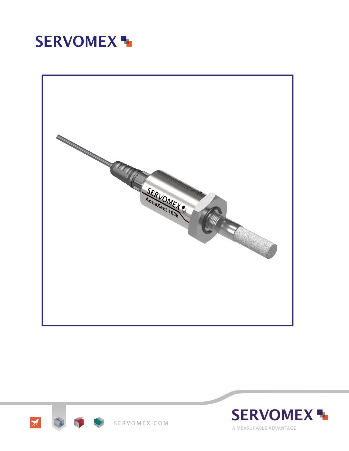
AquaXact 1688 Dew Point Transmitter
Operator Manual

2 © Servomex Group Limited 2017 AquaXact Issue 1.0
IMPORTANT INFORMATION
Continued safe and reliable operation of this equipment is conditional on all installation, operation and
maintenance procedures being carried out in accordance with the appropriate manuals, by personnel having
appropriate qualifications, experience and training. Failure to observe the requirements of the manual may result
in the user being held responsible for the consequences and may invalidate any warranty. Servomex accepts no
liability for unauthorised modifications to Servomex supplied equipment.
Servomex has paid particular attention to Health and Safety throughout this manual. Where special precautions
need to be taken due to the nature of the equipment or product, an appropriate safety icon and warning
message is shown. Special attention should be made to section 3 – Safety, where all such messages are
summarized.
This document, and all specifications and drawings within the document, are the property of Servomex, unless
agreed otherwise by contract, and are issued in strict confidence. They must not be reproduced, copied or
transmitted in any form, or by any means, or used as the basis for the manufacture or sale of apparatus,
programs or services without permission.
In line with our continuous policy of research and development, Servomex reserves the right to amend models
and specifications without prior notice, therefore the information in this document is subject to change without
notice and does not represent a commitment on the part of Servomex Group Limited. This handbook is accurate
at the date of printing, but will be superseded and should be disregarded if specifications or appearance are
changed. Check the internet for updates to the manual. The latest revision of this manual is available in Adobe
Acrobat format at www.servomex.com.
The customer agrees that in accepting and using this instrument Servomex’s liability arising from or in any way
connected with this instrument shall be limited exclusively to performing a new calibration or replacement or
repair of the instrument or sensor, at Servomex’s sole option, as covered by Servomex’s warranty. In no event
shall Servomex be liable for any incidental, consequential or special damages of any kind or nature whatsoever,
including but not limited to lost profits arising from or in any way connected with this instrument or items
hereunder, whether alleged to arise from breach of contract, express or implied warranty, or in tort, including
without limitation, negligence, failure to warn or strict liability.
Servomex is a registered trademark of Servomex Group Inc. The use of all trademarks in this document is
acknowledged.
North America:
Europe:
Representative:
Servomex Group Inc.
4 Constitution Way
Woburn MA 01801-1087
United States
Servomex Group Ltd
Jarvis Brook
Crowborough
East Sussex TN6 3FB
United Kingdom
t: +1 781 935 4600
+1 800 433 2552 (US toll free)
f: + 1 781 938 0531
e: americ[email protected]
w: www.servomex.com
t: + 44 (0) 1892 652 181
f: + 44 (0) 1892 662 253
e: europe_sales@servomex.com
w: www.servomex.com
© 2017. Servomex Group Limited. A Spectris Company. All rights reserved

AquaXact Issue 1.0 © Servomex Group Limited 2017 3
Contents
1Introduction ............................................................................................................................ 5
About this manual ........................................................................................................... 51.1
Product overview ............................................................................................................ 61.2
Product identification ....................................................................................................... 61.3
Ordering options ............................................................................................................. 61.4
2Unpacking............................................................................................................................... 7
3Safety ...................................................................................................................................... 8
Installation ....................................................................................................................... 83.1
Operation ........................................................................................................................ 93.2
Electromagnetic compatibility considerations .................................................................. 93.3
4Installation ............................................................................................................................ 10
Sensor installation ......................................................................................................... 104.1
Mechanical installation .................................................................................................. 134.2
Electrical installation...................................................................................................... 144.3
5Operation .............................................................................................................................. 16
Starting up .................................................................................................................... 16
5.1
6Technical specification ........................................................................................................ 17
Instrument ..................................................................................................................... 176.1
Sensor .......................................................................................................................... 186.2
Approvals / classifications ............................................................................................. 186.3
7Routine maintenance ........................................................................................................... 19
Preventative maintenance ............................................................................................. 197.1
8Troubleshooting ................................................................................................................... 20
Instrument ..................................................................................................................... 208.1
Sensor .......................................................................................................................... 218.2
9Storage and disposal ........................................................................................................... 23
Storage ......................................................................................................................... 239.1
Disposal ........................................................................................................................ 249.2
10 Spares ................................................................................................................................... 25
11 Warranty ............................................................................................................................... 26
Maintenance policy ....................................................................................................... 2711.1
Return Authorization Request ....................................................................................... 2711.2

4 © Servomex Group Limited 2017 AquaXact Issue 1.0
Appendix A Mechanical Drawings ......................................................................................... 29
A.1 Dew point transmitter .................................................................................................... 29
A.2 Sample block ................................................................................................................ 30
A.3 Sampling panel ............................................................................................................. 31
Appendix B Current vs. dew point ......................................................................................... 32
Appendix C Relationship of 4-20 mA output and instrument reading in ppmV or LBS ..... 34
Appendix D Uncertainty in LBS & ppmV calculations ......................................................... 35
Appendix E Sensor response time ........................................................................................ 36
E.1 AquaXact 1688 Calibration Options .............................................................................. 37
Index ............................................................................................................................................ 38

AquaXact Issue 1.0 © Servomex Group Limited 2017 5
1 Introduction
About this manual 1.1
1.1.1 Scope of the manual
This manual covers the installation, operation and routine maintenance of the AquaXact
1688 Dew Point Transmitter. It is intended for those already familiar with the installation,
use and maintenance of analytical or process instrumentation.
1.1.2 Safety information
Read this manual and make sure you fully understand its contents before you attempt to
install, use or maintain the device.
The following icons are used throughout this manual to identify any potential hazards that
could cause serious injury to people. Always follow the safety instructions and be aware of
the hazard.
This symbol warns of specific hazards which, if not taken into account,
may result in personal injury or death.
This symbol warns of specific hazards due to high voltages which, if not
taken into account, may result in personal injury or death.
This symbol warns of specific hazards due to high temperatures which, if
not taken into account, may result in personal injury or death.
This symbol warns of specific hazards due to hazardous substances
which, if not taken into account, may result in personal injury or death.
This symbol warns of specific hazards due to caustic or corrosive
substances which, if not taken into account, may result in personal injury
or death.
This symbol highlights where you must take special care to ensure the
equipment or property is not damaged.
1.1.3 Other information provided by the manual
Note:
Notes give extra information about the equipment.
Hint:
Hints give helpful tips and highlights information which is useful for you to be
aware of, for example, specific operating conditions.
6 © Servomex Group Limited 2017 AquaXact Issue 1.0
Product overview 1.2
The basic AquaXact 1688 dew point transmitter is a microprocessor based 4-20 mA loop-
powered hygrometer designed to measure moisture content in gases in a wide range from
-100 °C to +20 °C dew point in gases.
The measurement is transmitted by varying the current drawn (4-20 mA) from the power
supply, where the current varies in a proportional manner to the selected measurement
units.
In addition to the 4-20mA transmission a digital output can be used in conjunction with a
Servomex 1688 controller or MonoExact DF310E analyzer. Thus the AquaXact 1688 is
capable of communicating with properly equipped external computers or DCS systems as
well as the proprietary Servomex controllers. The AquaXact controller also allows field
span measurements and supports the field based sensor tip replacement process
(Appendix E). The AquaXact 1688’s advanced design allows it to be housed in a small
stainless steel enclosure behind the sensor probe making the transmitter and sensor a
single integrated unit.
The AquaXact 1688 uses the Servomex thin film Al2O3 technology sensor which is
encapsulated in sintered stainless steel making it compatible with a wide variety of
environments.
The sensor is a sensitive device and it should be handled accordingly.
Product identification 1.3
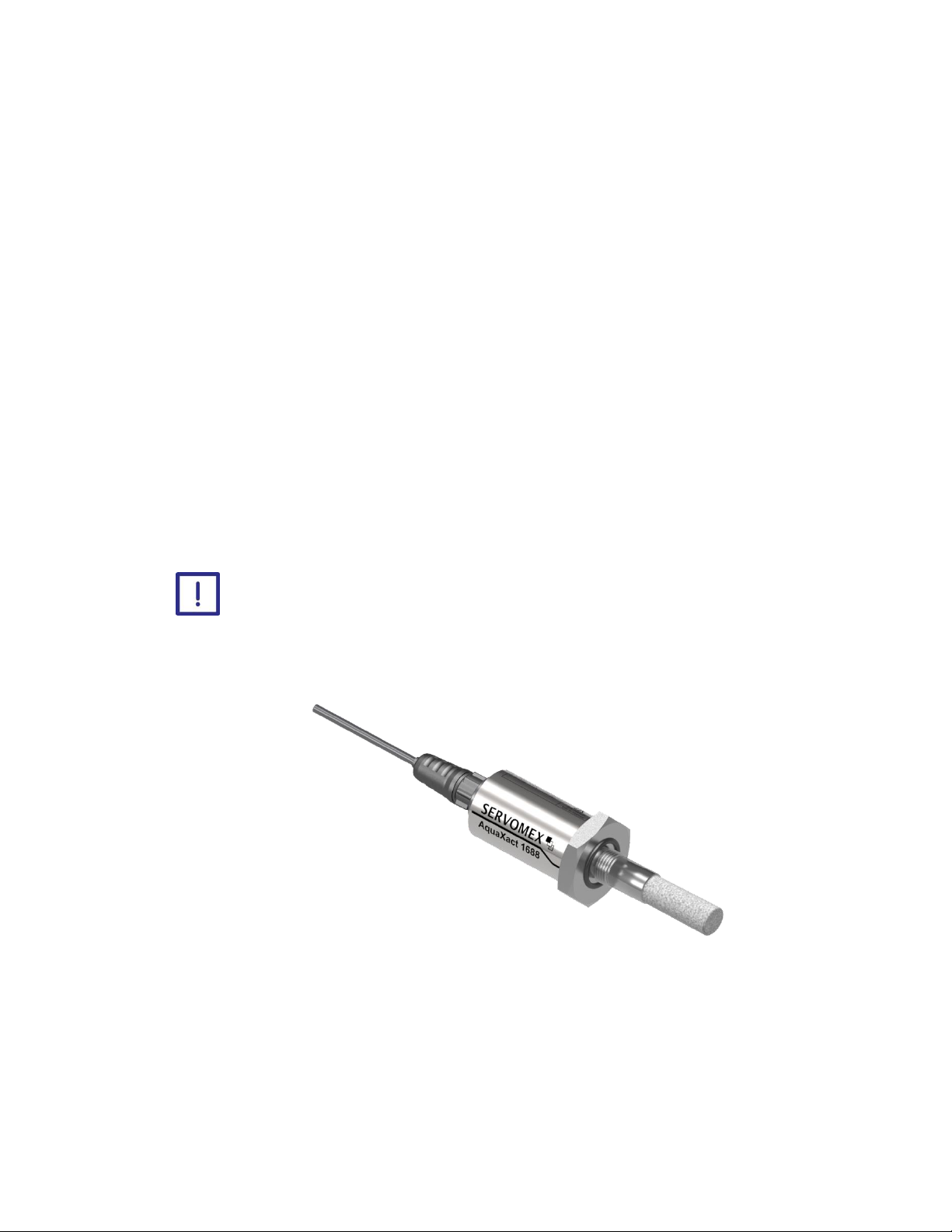
Figure 1-1: The AquaXact 1688 Dew Point Transmitter
Ordering options 1.4
For the latest ordering options please contact your local Servomex agent or visit
www.servomex.com.

AquaXact Issue 1.0 © Servomex Group Limited 2017 7
2 Unpacking
Read this manual carefully BEFORE you remove the AquaXact 1688 Dew
Point Transmitter from its box, or you attempt to install, commission or
use the equipment.
1. Examine the AquaXact package for damage or mishandling. If any damage is evident
notify the carrier and request an inspection.
2. Unpack the box. It should contain:
Transmitter and sensor in desiccant container. The transmitter should be stored in
the desiccant container when not in use.
Mating connector.
3. A USB memory stick with calibration files and an Adobe Acrobat file of this manual.
Check that you have received all of the items that you ordered. If any item is missing,
contact Servomex or your local Servomex agent immediately.
4. Inspect the items supplied, and check that they are not damaged. If any item is
damaged, contact Servomex or your local Servomex agent immediately.
5. Read section 3 – Safety before proceeding further.
Hint:
Keep the shipping documentation and packaging for future use, for example
when moving the equipment, or returning it for service or repair.

8 © Servomex Group Limited 2017 AquaXact Issue 1.0
3 Safety
The Servomex thin film Al2O3 sensor is designed and field proven to be highly reliable,
rugged and maintenance free. However the user should be aware of the following
precautions:
Installation 3.1
To avoid prolonged dry-down (when expecting to measure dew points
drier than -65 ºC), do not expose the sensor to room air longer than 1 - 2
minutes.
Do not open the desiccated sensor container before you are ready to
install the sensor.
The sensor container has desiccant to keep the sensor dry during
shipping and to avoid damage due to condensation. Close the container
using the attached red plug immediately after removing the sensor to
avoid degradation of the desiccant.
Do not throw away the sensor container. You may use it again to
transport the sensor between locations, to store it between uses or to
ship it back to the factory for certification. The container can be attached
to the loop cable, by trapping the cable with the lid strap.
Do not expose the sensor to corrosive gases or liquids such as ones
containing Chlorine, Ammonia or HCl. Cyanide, Br2, I2, NH3 and HNO3
may harm the gold layer of the sensor and limit the sensor life.
Do not expose the sensor to liquid water, as it may get damaged.
Do not breathe directly onto the sensor, as condensation may form
which could damage the sensor element.
Do not install the sensor near high heat sources such as radiators or air
ducts.
Do not install the sensor in places subject to extreme mechanical
vibration or shock.
Do not disassemble the porous metal filter encapsulation. This will
damage the sensor and void your factory warranty.
Before you install the probe, make sure that no contaminants are present
in the system (e.g. oil, liquid water).

AquaXact Issue 1.0 © Servomex Group Limited 2017 9
Operation 3.2
The AquaXact 1688 uses state-of-the-art microelectronics to provide a miniature full
functioning transmitter. The user should consider the following precautions when using any
sensitive electronic device:
Do not install the unit near heat sources such as radiators or air ducts.
Do not install the unit in places subject to extreme mechanical vibration
or shock.
Observe the appropriate electrical safety codes and regulations.
Electromagnetic compatibility considerations 3.3
The AquaXact 1688 has been designed and verified by testing to meet the requirements of
the EU EMC Directive 2014/30/EU, for Industrial, Scientific & Medical equipment. The
sensor and the 4-20 mA loop are electrically connected, however they are isolated from
the AquaXact 1688 housing and sample cell fitting threads. Please consider the following
electromagnetic interference issues during installation:
In order to provide an acceptable noise environment for the AquaXact 1688 or any
other digital equipment in the proximity of switching inductive loads, it is recommended
that there be varistors placed across the inductors to keep down the high voltage spikes
during transitions.
AC power wiring should be routed as far away from the AquaXact 1688 and its wiring
as practical.

10 © Servomex Group Limited 2017 AquaXact Issue 1.0
4 Installation
Do not attempt to install, commission, maintain or use the AquaXact
1688 Dew Point Transmitter unless you are trained and know what you
are doing.
Follow the instructions in this section to safely install the AquaXact 1688
Dew Point Transmitter.
Do not install the unit in places subject to extreme mechanical vibration
or shock. If you do, sample measurements may not be accurate and the
transmitter may be damaged.
Sensor installation 4.1
The moisture content at the sensor is not only due to the moisture of the gas being
measured, but is also due to desorption of water from tubing, trapped moisture (at the
interconnection points, valves, filters and other hygroscopic materials in the system), leaks
in the system and others. As a result the measurement may vary from what is expected
and care should be taken in choosing the sampling approach utilized in the measurement.
Factors such as gas pressure, flow rate, materials of construction, length and diameter of
tubing, number of interconnecting fittings, dead space in tubing and manifolds will
influence the observed measurement value and response time.
The high-capacitance thin-film sensor can be installed either directly in the line to be
sampled (in-situ), or in a slip stream of a sample system (extractive). To assure a long and
accurate performance of the sensor, it should be protected from contaminants such as
liquids (water, oil etc.), and particulates. The sintered stainless steel sensor encapsulation
protects from particulates larger than 100 microns, finer particulates (e.g. from degraded
desiccant or rust) should be filtered with a particulate filter with suitable capability, do not
use hygroscopic filter materials.
4.1.1 In-situ installation
In-situ installation is recommended only for measurements where the gas pressure is
expected to be constant, the gas is expected to be free of contaminants, the gas
temperature is within the operating specifications of the sensor and there is no chance of
liquids coalescing. Examples of applications suited for in-situ installations are pure gases
or output of desiccant dryers (for instrument air), glove boxes, etc. For most other
applications in-situ installation should be avoided for the following reasons:
Sample conditioning is almost always necessary to avoid exposure of the sensor to
liquid water and other contaminants, such as hydrocarbons, which may damage the
sensor or affect accuracy over time.
If the gas line is under pressure, it is more likely that water condensation occurs which
may damage the sensor.
Indice
Altri manuali Servomex Trasmettitore


