SICK WTB4-3Teach-in Manuale utente

OPERATING I N S T R U C T I O N
en / de / fr / it / pt / es / zh / ru
SICK AG, Erwin-Sick-Strasse 1, D-79183 Waldkirch
8011166.126R
2006/42/EG
NO
SAFETY

Photoelectric proximity sensor
Operating instructions
1 Safety notes
■Read the operating instructions before commissioning.
■Connection, mounting, and setting may only be performed by trained specialists.
■Not a safety component in accordance with the EU Machinery Directive.
■UL: Only for use in applications in accordance with NFPA 79. These devices shall
be protected by a 1 A fuse suitable for 30 V DC. Adapters listed by UL with connec‐
tion cables are available. Enclosure type 1.
■When commissioning, protect the device from moisture and contamination.
■These operating instructions contain information required during the life cycle of
the sensor.
2 Correct use
The WTB4-3 is an opto-electronic photoelectric proximity sensor (referred to as "sensor"
in the following) for the optical, non-contact detection of objects, animals, and persons.
If the product is used for any other purpose or modified in any way, any warranty claim
against SICK AG shall become void.
Photoelectric proximity sensor with background suppression.
Image: A
3 Commissioning
1 Check the application conditions: Adjust the sensing range and distance to the ob‐
ject or background and the remission capability of the object according to the cor‐
responding diagram [H] (x = sensing range, y = transition range between the set
sensing range and suppression of the background as a % of the sensing range (ob‐
ject remission / background remission). Remission: 6% = black , 18% = gray ,
90% = white (referring to standard white as per DIN 5033).
8011166.126R | SICK
Subject to change without notice 1
Technical data, see page 72.
The minimum distance (= y) for background suppression can be determined from
diagram [H] as follows:
Example: x = 100 mm, y = 7 => 7 % of 100 mm = 7 mm. That is, the background is
suppressed at a distance of > 107mm from the sensor.
25
5
10
15
20
0
mm
(inch)
25
(0.98)
50
(1.97)
75
(2.95)
100
(3.94)
125
(4.92)
150
(5.91)
Distance in mm (inch)
% of sensing distance
6 %/90 %
18 %/90 %
90 %/90 %
Image: H
2 Mount the sensor using a suitable mounting bracket (see the SICK range of acces‐
sories).
Note the sensor's maximum permissible tightening torque of 0.8 Nm.
Note the preferred direction of the object relative to the sensor [see A].
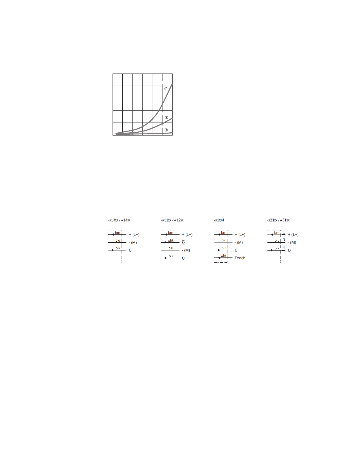
3 The sensors must be connected in a voltage-free state (VS = 0 V). The information
in the graphics [B] must be observed, depending on the type of connection:
– Male connector connection: pin assignment
– Cable: core color
Image: B
Only apply voltage/switch on the power supply (VS > 0 V) once all electrical connec‐
tions have been completed. The green LED indicator lights up on the sensor.
Explanations of the connection diagram (Graphic B):
Switching outputs Q and /Q (according to Graphic B):
Teach-in = external teach-in (ET) (see Adjustment)
WTB4-3Exxxx and WTB4-3Fxxxx
D: dark-switching, output (Q) switches off when an object is present in the sensing
range.
WTB4-3P1362 and WTB4-3Px1xx
WTB4-3N1362 and WTB3Nx1xx
L: light switching, output (Q) switches when an object is present in the sensing ran‐
ge.
WTB4-3P1162 and WTB4-3N1162
WTB4-3Px262 and WTB4-3Nx262
ANT: complementary outputs Q and Q/
WTB4-3Pxxx4 and WTB4-3Nxxx4
L: light switching, output (Q) switches when an object is present in the sensing ran‐
ge. In addition: ET: teach-in function via cable.
Connect ET cable (PIN 2) to UV for > 2 s (PNP output)
Connect ET cable (PIN 2) to M for > 2 s (NPN output)
3 COMMISSIONING
28011166.126R | SICK
Subject to change without notice

4 Align the sensor with the object. Select the position so that the red emitted light
beam hits the center of the object. You must ensure that the optical opening (front
screen) of the sensor is completely clear [E]. We recommend making the adjust‐
ments using an object with a low remission.
Image: E
5
Image: F
Sensor with teach-in button:
The sensing range is adjusted by pressing the teach-in button. Do not operate the
teach-in button using sharp objects. We recommend placing the switching state in
the object, e. g., see graphic F. Once the sensing range has been adjusted, the ob‐
ject is removed from the path of the beam, which causes the background to be
suppressed and the switching output to change (see graphic C).
The sensor is adjusted and ready for operation. Refer to graphics C and G to check
the function. If the switching output fails to behave in accordance with graphic C,
check application conditions. See section Fault diagnosis.
COMMISSIONING 3
3
8011166.126R | SICK
Subject to change without notice

Image: C
Image: G
Teach-in mode
for objects /
Teach-in mode
for objects
Teach-in time /
Teach-in time
Alignment /
Alignment
LED indicator /
LED indicator
Results /
Results
Single teach-in
pushbutton /
Single teach-in
pushbutton
Approx. 0.5 s /
Approx. 0.5 s
Sensor to ob‐
ject /
Sensor to object
Sensing range is
adjusted accor‐
ding to object /
Sensing range is
adjusted accor‐
ding to object
ET: Connect pin 2
or white wire to
UV for > 2 to < s
(PNP). /
ET: Connect pin 2
or white wire to
UV for > 2 to < s
(PNP).
> 2 s Sensor to ob‐
ject /
Sensor to object
Sensing range is
adjusted accor‐
ding to object /
Sensing range is
adjusted accor‐
ding to object
4
48011166.126R | SICK
Subject to change without notice

5 Fault diagnosis
Table indicates which measures are to be taken if the sensor stops working.
6 Table Fault diagnosis
LED indicator/fault pattern /
LED indicator/fault pattern
Cause /
Cause
Measures /
Measures
Green LED does not light up /
Green LED does not light up
No voltage or voltage below
the limit values /
No voltage or voltage below
the limit values
Check the power supply,
check all electrical connecti‐
ons (cables and plug connecti‐
ons) /
Check the power supply,
check all electrical connecti‐
ons (cables and plug connecti‐
ons)
Green LED does not light up /
Green LED does not light up
Voltage interruptions /
Voltage interruptions
Ensure there is a stable power
supply without interruptions /
Ensure there is a stable power
supply without interruptions
Green LED does not light up /
Green LED does not light up
Sensor is faulty /
Sensor is faulty
If the power supply is OK, re‐
place the sensor /
If the power supply is OK, re‐
place the sensor
Yellow LED flashes /
Yellow LED flashes
Sensor is still ready for opera‐
tion, but the operating conditi‐
ons are not ideal /
Sensor is still ready for opera‐
tion, but the operating conditi‐
ons are not ideal
Check the operating conditi‐
ons: Fully align the beam of
light (light spot) with the ob‐
ject. / Clean the optical surfa‐
ces . / Readjust the sensitivity
(teach-in) / Check sensing
range and adjust if necessary;
see graphic F. /
Check the operating conditi‐
ons: Fully align the beam of
light (light spot) with the ob‐
ject. / Clean the optical surfa‐
ces . / Readjust the sensitivity
(teach-in) / Check sensing
range and adjust if necessary;
see graphic F.
Yellow LED flashes (only brie‐
fly) /
Yellow LED flashes (only briefly)
Teach-in mode /
Teach-in mode
Check the teach-in mode /
Check the teach-in mode
Yellow LED lights up, no object
in the path of the beam /
Yellow LED lights up, no object
in the path of the beam
/ Distance between the sen‐
sor and the background is too
short /
/ Distance between the sen‐
sor and the background is too
short
Reduce the sensing range,
see graphic F /
Reduce the sensing range,
see graphic F
Object is in the path of the be‐
am, yellow LED does not light
up /
Object is in the path of the be‐
am, yellow LED does not light
up
Distance between the sensor
and the object is too long or
sensing range is set too
short /
Distance between the sensor
and the object is too long or
sensing range is set too short
Increase the sensing range,
see graphic F /
Increase the sensing range,
see graphic F
FAULT DIAGNOSIS 5
5
8011166.126R | SICK
Subject to change without notice

7 Disassembly and disposal
The sensor must be disposed of according to the applicable country-specific regulati‐
ons. Efforts should be made during the disposal process to recycle the constituent ma‐
terials (particularly precious metals).
8 Maintenance
SICK sensors are maintenance-free.
We recommend doing the following regularly:
•Clean the external lens surfaces
•Check the screw connections and plug-in connections
No modifications may be made to devices.
Subject to change without notice. Specified product properties and technical data are
not written guarantees.
7 DISASSEMBLY AND DISPOSAL
68011166.126R | SICK
Subject to change without notice

Reflexions-Lichttaster
Betriebsanleitung
9Sicherheitshinweise
■Vor der Inbetriebnahme die Betriebsanleitung lesen.
■Anschluss, Montage und Einstellung nur durch Fachpersonal.
■Kein Sicherheitsbauteil gemäß EU-Maschinenrichtlinie.
■UL: Nur zur Verwendung in Anwendungen gemäß NFPA 79. Diese Geräte müssen
mit einer für 30V DC geeigneten 1A-Sicherung abgesichert werden. Von UL geliste‐
te Adapter mit Anschlusskabeln sind verfügbar. Enclosure type 1.
■Gerät bei Inbetriebnahme vor Feuchte und Verunreinigung schützen.
■Diese Betriebsanleitung enthält Informationen, die während des Lebenszyklus des
Sensors notwendig sind.
10 Bestimmungsgemäße Verwendung
Die WTB4-3 ist ein optoelektronischer Reflexions-Lichttaster (im Folgenden Sensor ge‐
nannt) und wird zum optischen, berührungslosen Erfassen von Sachen, Tieren und Per‐
sonen eingesetzt. Bei jeder anderen Verwendung und bei Veränderungen am Produkt
verfällt jeglicher Gewährleistungsanspruch gegenüber der SICK AG.
Reflexionslichttaster mit Hintergrundausblendung.
Abb.: A
7
Technische Daten siehe Seite 72.
8011166.126R | SICK
Subject to change without notice

11 Inbetriebnahme
1 Einsatzbedingungen prüfen: Schaltabstand und Distanz zum Objekt bzw. Hinter‐
grund sowie Remissionsvermögen des Objektes mit dem zugehörigen Diagramm
[vgl. H] abgleichen (x = Schaltabstand, y = Übergangsbereich zwischen eingestell‐
tem Schaltabstand und Ausblendung des Hintergrundes in % des Schaltabstands
(Remission Objekt / Remission Hintergrund)). Remission: 6 % = schwarz , 18 % =
grau , 90 % = weiß (bezogen auf Standardweiß nach DIN 5033).
Die minimale Distanz (= y) für die Hintergrundausblendung kann aus dem Dia‐
gramm [vgl. H] wie folgt ermittelt werden:
Beispiel: x = 100 mm, y = 7 => 7 % von 100 mm = 7 mm. D. h. der Hintergrund
wird ab einer Distanz von > 107 mm vom Sensor ausgeblendet.
25
5
10
15
20
0
mm
(inch)
25
(0.98)
50
(1.97)
75
(2.95)
100
(3.94)
125
(4.92)
150
(5.91)
Distance in mm (inch)
% of sensing distance
6 %/90 %
18 %/90 %
90 %/90 %
Abb.: H
2 Den Sensor an einen geeigneten Befestigungswinkel montieren (siehe SICK-Zube‐
hör-Programm).
Maximal zulässiges Anzugsdrehmoment des Sensors von 0.8 Nm beachten.
Vorzugsrichtung des Objektes zum Sensor beachten [vgl. A].
3 Anschluss der Sensoren muss spannungsfrei (VS = 0 V) erfolgen. Je nach An‐
schlussart sind die Informationen in den Grafiken [vgl. B] zu beachten:
– Steckeranschluss: Pinbelegung
– Leitung: Adernfarbe
10 BESTIMMUNGSGEMÄSSE VERWENDUNG
88011166.126R | SICK
Subject to change without notice

Abb.: B
Erst nach Anschluss aller elektrischen Verbindungen die Spannungsversorgung (VS
> 0 V) anlegen bzw. einschalten. Am Sensor leuchtet die grüne Anzeige-LED.
Erläuterungen zum Anschlussschema (Grafik B):
Schaltausgänge Q bzw. /Q (gemäß Grafik B):
Teach = externer Teach (ET) (siehe Einstellung)
WTB4-3Exxxx und WTB4-3Fxxxx
D: dunkelschaltend, Ausgang (Q) schaltet aus, wenn sich ein Objekt im Tastbereich
befindet.
WTB4-3P1362 und WTB4-3Px1xx
WTB4-3N1362 und WTB3Nx1xx
L: hellschaltend, Ausgang (Q) schaltet, wenn sich ein Objekt im Tastbereich befin‐
det.
WTB4-3P1162 und WTB4-3N1162
WTB4-3Px262 und WTB4-3Nx262
ANT: Antivalente Ausgänge Q und Q/
WTB4-3Pxxx4 und WTB4-3Nxxx4
L: hellschaltend, Ausgang (Q) schaltet, wenn sich ein Objekt im Tastbereich befin‐
det. Zusätzlich: ET: Teach-Funktion über Leitung.
Leitung ET (PIN 2) > 2 s auf UV legen (PNP-Ausgang)
Leitung ET (PIN 2) > 2 s auf M legen (NPN-Ausgang)
4 Sensor auf Objekt ausrichten. Positionierung so wählen, dass der rote Sendelicht‐
strahl in der Mitte des Objekts auftrifft. Es ist darauf zu achten, dass die optische
Öffnung (Frontscheibe) des Sensors vollständig frei ist [vgl. E]. Wir empfehlen, die
Einstellung mit einem Objekt von niedriger Remission vorzunehmen.
Abb.: E
INBETRIEBNAHME 11
9
8011166.126R | SICK
Subject to change without notice
Indice
Lingue:
Altri manuali SICK Accessori

SICK
SICK Lector620 Manuale utente

SICK
SICK DC12-24V Manuale utente

SICK
SICK DME4000 Manuale utente

SICK
SICK IQ80-50BPP-KC0 Manuale utente

SICK
SICK SIM1004 Manuale utente

SICK
SICK RMS3 Series Manuale utente

SICK
SICK AS30 Prime Edge Manuale utente

SICK
SICK HTB18 Manuale utente

SICK
SICK MIS Manuale utente

SICK
SICK TiM781 Manuale utente

SICK
SICK MPS-G Manuale utente

SICK
SICK Lector64x Flex Manuale utente

SICK
SICK OL1 Manuale utente

SICK
SICK WLA26 Series Manuale utente

SICK
SICK HTE18 Series Manuale utente

SICK
SICK GTB6L Manuale utente

SICK
SICK GSE2 Flat Side Manuale utente

SICK
SICK OD1000 Manuale utente

SICK
SICK PowerProx Mini WTT4SLC Manuale utente

SICK
SICK VISIC100SF Manuale utente


