SICK i10P Manuale utente

OPERATING INSTRUCTIONS
i10P, i10R
Safety position switch

Described product
i10P, i10R
Manufacturer
SICK AG
Erwin-Sick-Str. 1
79183 Waldkirch
Germany
Legal information
This work is protected by copyright. Any rights derived from the copyright shall be
reserved for SICK AG. Reproduction of this document or parts of this document is
only permissible within the limits of the legal determination of Copyright Law. Any modi‐
fication, abridgment or translation of this document is prohibited without the express
written permission of SICK AG.
The trademarks stated in this document are the property of their respective owner.
© SICK AG. All rights reserved.
Original document
This document is an original document of SICK AG.
2O P E R A T I N G I N S T R U C T I O N S | i10P, i10R 8027228/1CY5/2022-05-24 | SICK
Subject to change without notice

Contents
1 Scope.................................................................................................. 4
2 On safety............................................................................................. 5
2.1 Qualified safety personnel....................................................................... 5
2.2 Applications of the safety switches......................................................... 5
2.3 Correct use................................................................................................ 5
2.4 General protective notes and protective measures............................... 6
3 Mounting............................................................................................. 7
3.1 Change actuator entry direction.............................................................. 8
3.2 Protection against surroundings.............................................................. 8
4 Electrical installation........................................................................ 9
5 Commissioning.................................................................................. 10
5.1 Tests before the first commissioning...................................................... 10
5.2 Periodic technical inspections................................................................. 10
6 Disposal.............................................................................................. 11
7 Technical specifications................................................................... 12
7.1 General system data................................................................................ 12
7.2 Dimensional drawings.............................................................................. 13
8 Conformities and certificates.......................................................... 14
8.1 EU declaration of conformity.................................................................... 14
8.2 UK declaration of conformity................................................................... 14
CONTENTS
8027228/1CY5/2022-05-24 | SICK O P E R A T I N G I N S T R U C T I O N S | i10P, i10R 3
Subject to change without notice

1 Scope
These operating instructions are applicable to the i10R and i10P safety position
switches.
These operating instructions are original operating instructions.
1 SCOPE
4O P E R A T I N G I N S T R U C T I O N S | i10P, i10R 8027228/1CY5/2022-05-24 | SICK
Subject to change without notice

2 On safety
This chapter deals with your own safety and the safety of the equipment operators.
bThese operating instructions are applicable to the i10R and i10P safety position
switches.
The national/international rules and regulations apply to the installation, commission‐
ing, use and periodic technical inspections of the safety switches, in particular
•the Machinery Directive,
•the Low Voltage Directive,
•the Work Equipment Directive,
•the safety regulations as well as
•the work safety regulations/safety rules.
Manufacturers and operators of the machine on which the protective devices are used
are responsible for obtaining and observing all applicable safety regulations and rules.
2.1 Qualified safety personnel
Only qualified safety personnel are authorised to mount, install and commission the
safety position switch i10R/i10P. Qualified safety personnel are defined as persons
who
•have undergone the appropriate technical training
and
•have been instructed by the responsible machine owner in the operation of the
machine and the current valid safety guidelines
and
•who have access to these operating instructions.
2.2 Applications of the safety switches
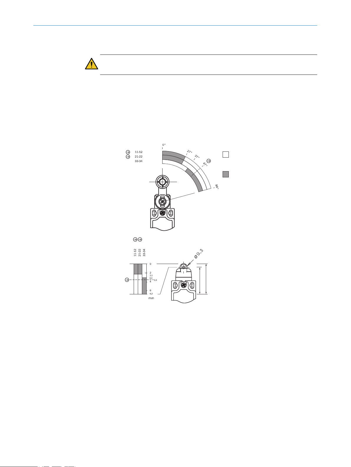
Safety position switches of type series i10R/i10P are position switches with forced
opening that are activated by roller levers (R) or roller tappets (P). They meet the
requirements according to EN 60947-5-1.
•the dangerous state of the machine can only be switched on when the guard is
closed,
•a STOP command is triggered if the protective device is opened while the machine
is operating.
For the control this means that
•activation commands that cause dangerous conditions, may only become active
when the guard is in the protective position and the dangerous conditions have
been terminated before the protective position is cancelled.
Prior to the use of safety switches, a risk assessment must be performed on the
machine.
2.3 Correct use
Safety position switch i10R/i10P must only be applied as defined in section 2.2 “Appli‐
cations of the safety position switch”. The safety position switch must only be used on
the machine where it has been fitted, installed and by qualified safety personnel and in
compliance with these operating instructions.
ON SAFETY 2
8027228/1CY5/2022-05-24 | SICK O P E R A T I N G I N S T R U C T I O N S | i10P, i10R 5
Subject to change without notice

If the device is used for any other purposes or modified in any way – also during
mounting and installation – any warranty claim against SICK AG shall become void.
The correct use includes the regular inspection of the protective device by qualified
safety personnel in accordance with section 5.2.
2.4 General protective notes and protective measures
Safety position switches serve the purpose of protecting individuals. Tampering or
incorrect installation may result in severe personal injury.
WARNING
Do not override safety position switches (by bridging contacts), turn them from their
protective position, remove them or defeat them in any other way.
2 ON SAFETY
6O P E R A T I N G I N S T R U C T I O N S | i10P, i10R 8027228/1CY5/2022-05-24 | SICK
Subject to change without notice

3 Mounting
WARNING
Mounting is only allowed to be performed by qualified safety personnel.
bPay attention to EN ISO 14119 on mounting the safety switch.
Mount the safety position switch such that
•It is difficult to access by operating personnel when the protective equipment is
open.
•it can be inspected and replaced.
WARNING
Do not use the safety position switch as a mechanical stop.
WARNING
The safety position switch must be adequately secured against movement.
In order to meet these requirements,
•the mounting components must be reliable and require a tool to be released,
•the use of elongated holes must be restricted to the initial settings,
•the roller lever must be mounted on the motor shaft with a positive fit.
bAssemble safety switch with 2 bolts M4 and tighten screws at 2.5–3 Nm.
bTake note of the data in the switch-path diagram when mounting the radial cam.
21
PA
RA
Contacts open
Contacts closed
Idle position
End position
Figure 1: Switching position diagram RA = roller lever, PA = roller tappet)
MOUNTING 3
8027228/1CY5/2022-05-24 | SICK O P E R A T I N G I N S T R U C T I O N S | i10P, i10R 7
Subject to change without notice

3.1 Change actuator entry direction
1. Undo screws on actuating head.
2. Set direction required (4 × 90°).
3. Tighten screws to 0.4–0.45 Nm.
3.2 Protection against surroundings
A precondition for a durable and perfect safety function is the protection of the
actuating head against penetration by foreign matter such as shavings, sand, abrasive
materials etc.
Cover the control slot, the actuator and the type label when painting.
3 MOUNTING
8O P E R A T I N G I N S T R U C T I O N S | i10P, i10R 8027228/1CY5/2022-05-24 | SICK
Subject to change without notice

4 Electrical installation
DANGER
The electrical connection is only allowed to be made by qualified safety personnel.
bInstall cable connector M20 with the required IP protection.
bConnection see figure 2
bOperate all contact pairs within the same voltage range.
bConnect all live parts on one side of the contact block.
bTighten clamping screws to 0.9 ... 1.0 Nm.
bCheck sealing at conduit entry.
bClose switch lid and tighten screws.
21
PA
RA
Contacts open
Contacts closed
Idle position
End position
Figure 2: Switching position diagram RA = roller lever, PA = roller tappet)
ELECTRICAL INSTALLATION 4
8027228/1CY5/2022-05-24 | SICK O P E R A T I N G I N S T R U C T I O N S | i10P, i10R 9
Subject to change without notice

5 Commissioning
5.1 Tests before the first commissioning
•Mechanical function test
bTest the movement of the roller lever/roller tappet for smoothness of operation.
•Electrical function test
bActuate the roller lever/roller tappet and test the switching function.
•Electrical performance test in safety switching circuits.
bClose safety guard.
bTurn on machine.
WARNING
Check whether opening the safety guard stops the machine.
bTurn off machine.
bOpen safety guard.
WARNING
Machine must not start while safety guard is open!
5.2 Periodic technical inspections
To ensure correct function over the long term, regular checks are necessary.
Daily or prior to the start of the shift the operator must check for:
•correct function
•no visible evidence of tampering
Regularly according to the machine maintenance schedule by qualified safety person‐
nel:
•correct switching function
•safe mounting of the modules
•deposits and wear and tear
•correct sealing of the cable entry or plug connection
•loose cable connections or plug connectors
DANGER
The entire switch and actuator must be replaced in the case of damage or wear and
tear. It is not permitted to exchange individual components or modules!
Safety switches must be completely replaced after 1 million switching operations.
5 COMMISSIONING
10 O P E R A T I N G I N S T R U C T I O N S | i10P, i10R 8027228/1CY5/2022-05-24 | SICK
Subject to change without notice
Questo manuale è adatto per i seguenti modelli
1
Indice
Altri manuali SICK Interruttore

SICK
SICK T4000 Direct Unicode Manuale utente

SICK
SICK ES21 Manuale utente

SICK
SICK T4000 Direct Unicode Manuale utente

SICK
SICK TR4 Manuale utente

SICK
SICK L25 Manuale utente

SICK
SICK IQB2S Manuale utente

SICK
SICK RE1 Manuale utente

SICK
SICK i10R Manuale utente

SICK
SICK ES11 Manuale utente

SICK
SICK SLG-2 Manuale utente

SICK
SICK WSU 26/2 Manuale elenco delle parti

SICK
SICK WLL190T-2 Manuale utente

SICK
SICK PAC50 Manuale utente

SICK
SICK MSL Series Manuale utente

SICK
SICK T4000 Direct Unicode Manuale utente

SICK
SICK LFV 310 Manuale utente

SICK
SICK ES11-SA1A4 Manuale utente

SICK
SICK TR4 Manuale utente

SICK
SICK TBS Manuale utente

SICK
SICK i17S Manuale utente


