SICK IN4000 Standard Manuale utente

OPERATING INSTRUCTIONS
IN4000 Standard
Safety switches
Described product
IN4000 Standard
Manufacturer
SICK AG
Erwin-Sick-Str. 1
79183 Waldkirch
Germany
Legal information
This work is protected by copyright. Any rights derived from the copyright shall be
reserved for SICK AG. Reproduction of this document or parts of this document is
only permissible within the limits of the legal determination of Copyright Law. Any modi‐
fication, abridgment or translation of this document is prohibited without the express
written permission of SICK AG.
The trademarks stated in this document are the property of their respective owner.
© SICK AG. All rights reserved.
Original document
This document is an original document of SICK AG.
2O P E R A T I N G I N S T R U C T I O N S | IN4000 Standard 8027276/1CZ6/2022-12-13 | SICK
Subject to change without notice

Contents
1 About this document........................................................................ 5
1.1 Purpose of this document........................................................................ 5
1.2 Target group.............................................................................................. 5
1.3 Information depth..................................................................................... 5
1.4 Scope......................................................................................................... 5
1.5 Symbols and document conventions...................................................... 6
2 On safety............................................................................................. 7
2.1 Qualified safety personnel....................................................................... 7
2.2 Applications of the safety switches......................................................... 7
2.3 Intended use............................................................................................. 8
2.4 Reasonably foreseeable misuse.............................................................. 8
2.5 General safety notes and protective measures...................................... 8
3 Product description........................................................................... 10
3.1 IN4000 Standard Series safety switches................................................ 10
3.2 Features and principle of operation........................................................ 10
3.3 Enable zone and assured switch-off distance........................................ 10
3.4 LED indicators........................................................................................... 12
3.4.1 Displays in operating mode..................................................... 12
3.4.2 Displays in adjustment mode................................................. 12
3.5 Signal behavior......................................................................................... 13
3.6 Response times of the safety switch....................................................... 14
3.7 Manipulation prevention.......................................................................... 15
4 Mounting............................................................................................. 16
4.1 Mounting the IN40-D0101K safety switch............................................. 16
4.2 Mounting the IN40-D03.. and IN40-D0202K safety switches.............. 18
5 Connection and adjustment............................................................ 20
5.1 Electrical connection................................................................................ 20
5.2 Series connection of inductive safety switches...................................... 21
5.3 Adjustment................................................................................................ 21
6 Commissioning and operation........................................................ 22
6.1 Checks before initial commissioning....................................................... 22
6.1.1 Checking the start function..................................................... 22
6.2 Periodic technical inspections................................................................. 22
6.2.1 Daily check............................................................................... 22
6.2.2 Inspections by qualified safety personnel.............................. 22
6.3 Response to errors................................................................................... 23
7 Troubleshooting................................................................................. 24
7.1 Safety......................................................................................................... 24
7.2 Troubleshooting........................................................................................ 24
CONTENTS
8027276/1CZ6/2022-12-13 | SICK O P E R A T I N G I N S T R U C T I O N S | IN4000 Standard 3
Subject to change without notice

7.3 Safe status when an error occurs............................................................ 24
8 Maintenance...................................................................................... 25
8.1 Maintenance............................................................................................. 25
9 Decommissioning............................................................................. 26
9.1 Disposal..................................................................................................... 26
10 Technical data.................................................................................... 27
10.1 Data sheet................................................................................................. 27
10.2 Pin assignment......................................................................................... 28
10.3 Dimensional drawings.............................................................................. 29
11 Ordering information........................................................................ 30
11.1 Devices...................................................................................................... 30
11.2 Accessories............................................................................................... 30
12 Annex.................................................................................................. 31
12.1 Conformities and certificates................................................................... 31
12.1.1 EU declaration of conformity................................................... 31
12.1.2 UK declaration of conformity.................................................. 31
13 List of figures..................................................................................... 32
14 List of tables....................................................................................... 33
CONTENTS
4O P E R A T I N G I N S T R U C T I O N S | IN4000 Standard 8027276/1CZ6/2022-12-13 | SICK
Subject to change without notice

1 About this document
1.1 Purpose of this document
These operating instructions provide technical personnel of the machine manufacturer
ormachine operator with instructions regarding the safe mounting, parameterization,
electrical installation, commissioning, operation and thorough check of the inductive
safety switch.
These operating instructions do not provide information on operating the machine in
which a safety switch is integrated. For information about this, refer to the operating
instructions of the specific machine.
1.2 Target group
These operating instructions are intended for planning engineers, developers, and oper‐
ating entities of plants and systems that are to be protected by one or more inductive
safety switches. They are also intended for people who integrate the safety switch into a
machine, or perform the initial commissioning or inspection.
1.3 Information depth
These operating instructions contain information about the inductive safety switch on
the following topics:
•Mounting,
•Electrical installation,
•Hardware commissioning,
•Fault diagnosis and troubleshooting,
•Part numbers,
•Conformity and approval.
Please note that technical skills not covered by this document are also required when
planning and using SICK protective devices.
The official and legal regulations for operating the inductive safety switch must always
be complied with.
General information on the topic of safety technology can be found in the “Guide for
Safe Machinery”.
NOTE
Please also refer to the website at: www.sick.com
There you will find:
•example applications
•a list of frequently asked questions
1.4 Scope
Product
This document applies to the following products:
•Product code: IN4000 Standard
Document identification
Document part number:
•This document: 8027276
•Available language versions of this document: 8010934
ABOUT THIS DOCUMENT 1
8027276/1CZ6/2022-12-13 | SICK O P E R A T I N G I N S T R U C T I O N S | IN4000 Standard 5
Subject to change without notice

You can find the current version of all documents at www.sick.com.
1.5 Symbols and document conventions
The following symbols and conventions are used in this document:
Safety notes and other notes
DANGER
Indicates a situation presenting imminent danger, which will lead to death or serious
injuries if not prevented.
WARNING
Indicates a situation presenting possible danger, which may lead to death or serious
injuries if not prevented.
CAUTION
Indicates a situation presenting possible danger, which may lead to moderate or minor
injuries if not prevented.
NOTICE
Indicates a situation presenting possible danger, which may lead to property damage if
not prevented.
NOTE
Indicates useful tips and recommendations.
Instructions to action
bThe arrow denotes instructions to action.
1. The sequence of instructions for action is numbered.
2. Follow the order in which the numbered instructions are given.
✓The check mark denotes the result of an instruction.
LED symbols
These symbols indicate the status of an LED:
oThe LED is off.
ÖThe LED is flashing.
OThe LED is illuminated continuously.
1 ABOUT THIS DOCUMENT
6O P E R A T I N G I N S T R U C T I O N S | IN4000 Standard 8027276/1CZ6/2022-12-13 | SICK
Subject to change without notice

2 On safety
This section concerns your own safety and the safety of the system operator.
bPlease read this section carefully before you begin working with the IN4000 Stand‐
ard series of inductive safety switches, or the machine protected by these safety
switches in conjunction with the corresponding protective devices.
National and international legal regulations apply to the use/installation of the IN4000
Standard series of safety switches as well as to their commissioning and recurring
technical inspections, in particular
•the Machinery Directive,
•the EMC Directive,
•the Work Equipment Directive,
•the safety regulations, and
•the accident prevention regulations and work safety regulations.
2.1 Qualified safety personnel
The safety switches must only be installed and commissioned by qualified safety per‐
sonnel. A person is considered qualified safety personnel if he/she
•has taken part in adequate technical training
and
•has been instructed by the machine operator in machine operation and the appli‐
cable safety guidelines
and
•can access these operating instructions.
2.2 Applications of the safety switches
The IN4000 Standard series of safety switches are inductive safety proximity switches
that are actuated by metal in a non-contact manner. The safe state is the de-energized
state.
The IN4000 Standard series of safety switches and the corresponding machine or
system controller can be used, for example, to protect movable physical guards in such
a way that:
•the dangerous state of the machine or system can only be switched on when the
protective devices are closed.
•a stop command is triggered if a protective device is opened while the machine is
running.
For the controller, this means that:
•switch-on commands that result in dangerous states may only be activated when
the protective devices are in the protective position,
and
•dangerous states must be ended before the protective devices are moved out of
the protective position.
Before using the safety switches, a risk assessment must be carried out on the
machine.
Intended use also includes compliance with the relevant requirements for installation
and operation.
ON SAFETY 2
8027276/1CZ6/2022-12-13 | SICK O P E R A T I N G I N S T R U C T I O N S | IN4000 Standard 7
Subject to change without notice

The safety switches must be subjected to periodic technical inspections (see "Periodic
technical inspections", page 22).
2.3 Intended use
The IN4000 Standard series of safety switches may only be used as described in
section “Applications of the safety switches”. The safety switches may only be installed
by qualified safety personnel and may only be used on the machine on which they
were installed and commissioned for the first time by qualified safety personnel in
accordance with these operating instructions.
The product may be used in safety functions.
The safety switch must only be used within the limits of the prescribed and specified
technical data and operating conditions at all times.
If used in any other way or if alterations are made to the devices – including in the
context of mounting and installation – any warranty claims directed to SICK AG will be
rendered void.
2.4 Reasonably foreseeable misuse
The safety switch is not suitable for the following applications, among others:
•In the vicinity of chemical and biological media (solid, liquid, gaseous)
•In environments with increased levels of ionizing radiation
2.5 General safety notes and protective measures
The safety switch performs a personal protection function. Improper installation or
manipulation can lead to serious personal injuries.
The safety switch complies with the following safety requirements:
•SIL3 according to IEC 61508,
•SILCL3 according to EN 62061,
•Performance Level e according to EN ISO 13849-1 (depending on application).
Change information
•For devices up to CW24 2018, the following applies:
PFHD 1.33 × 10⁻⁹/Category 4 (EN ISO 13849-1)
•For devices on or after CW25 2018, the following applies :
PFHD 1.0 × 10⁻⁸/Category 3 (EN ISO 13849-1)
bPlease check whether the device meets the safety requirements of your applica‐
tion.
Note regarding the classification of the device according to EN60947--5-2:
•The IN40-D0101K safety switch complies with I1C40SP2M or I2C40SP2M classifi‐
cation, depending on the installation method.
•The IN40-D0303K safety switch complies with the I2A18SP2M classification.
•The IN40-D0202K safety switch complies with the I2A30SP2M classification.
•The IN40-D0304K safety switch complies with the I1A18SP2M classification.
2 ON SAFETY
8O P E R A T I N G I N S T R U C T I O N S | IN4000 Standard 8027276/1CZ6/2022-12-13 | SICK
Subject to change without notice

WARNING
Safety switches must not be circumvented, rotated away, removed, or rendered ineffec‐
tive in any other way. Their contacts must not be bridged.
The inductive safety switches respond to metallic objects. Other metallic objects that
are not intended to trigger the safety function must not be placed on the sensing face
of the safety switches under any circumstances. Appropriate measures must therefore
be taken to prevent this.
Please observe the installation measures according to ENISO14119.
Damaged devices must be replaced.
ON SAFETY 2
8027276/1CZ6/2022-12-13 | SICK O P E R A T I N G I N S T R U C T I O N S | IN4000 Standard 9
Subject to change without notice
3 Product description
3.1 IN4000 Standard Series safety switches
The IN4000 Standard series of safety switches are based on the same principle of
operation, but differ in their design, installation method, response ranges, and classifi‐
cation.
The IN40-D0101K safety switch has a cuboid housing with an alignable active sensor
face. It can also be installed flush or flush on one side, except in steel.
The IN40-D0303K and IN40-D0202K safety switches are enclosed in a cylindrical
housing and are not suitable for flush or one-sided flush installation.
The IN40-D0304K safety switch is enclosed in a cylindrical housing and is suitable for
flush installation.
3.2 Features and principle of operation
The IN4000 Standard series of safety switches are typically used for safe posi‐
tion detection, as is the case, for example, when monitoring a movable protective
device. The sensor detects the presence of metal. In order to meet the requirements
against easy manipulation, the switching range of the sensor is monitored in time and
space.
Its status can be read directly on the sensor or the protective device by means of
LEDs. Errors, such as a coil break, short-circuit or wire break are detected by the
self-monitoring function of the sensor.
The safety switch can be connected directly to a safe PLC or to a SICK safety controller,
e.g., Flexi Classic or Flexi Soft.
The IN4000 Standard series of safety switches can be cascaded (see "Series connec‐
tion of inductive safety switches", page 21).
Information on connection can also be found in the operating instructions of the safety
controller used (e.g., Flexi Classic or Flexi Soft).
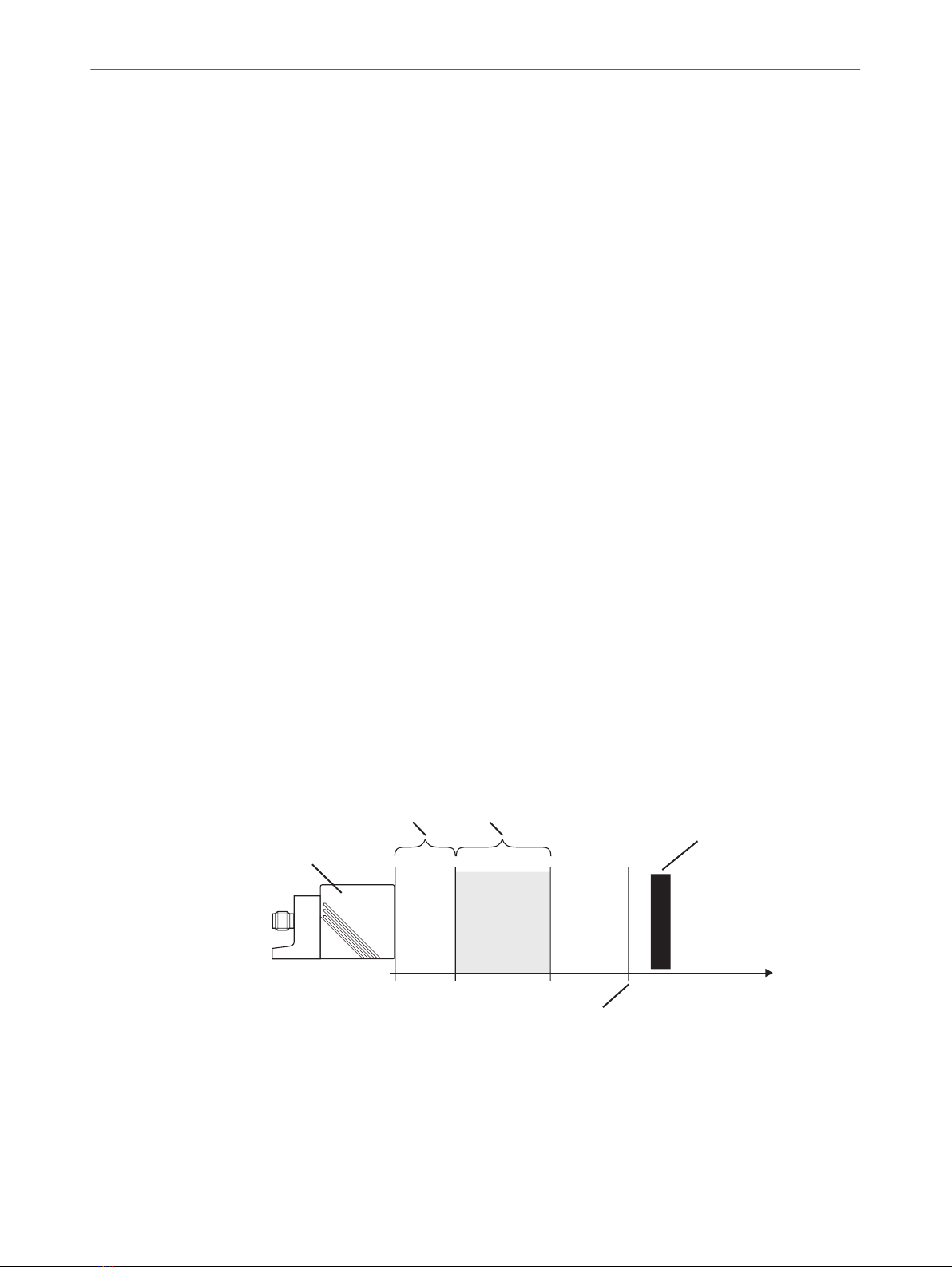
3.3 Enable zone and assured switch-off distance
Near range Enable Zone Actuating object
(metal)
Safe switch off
distance
Sensor
Distance
Figure 1: Schematic illustration of the zones
The output of the safety switch is only enabled in the event of actuation within the
enable zone. Outside the enable zone, i.e., also in the close range, the output remains
switched off.
3 PRODUCT DESCRIPTION
10 O P E R A T I N G I N S T R U C T I O N S | IN4000 Standard 8027276/1CZ6/2022-12-13 | SICK
Subject to change without notice
Indice
Altri manuali SICK Interruttore

SICK
SICK MLP1 Manuale utente

SICK
SICK TR4 Manuale utente

SICK
SICK i110P Manuale utente

SICK
SICK T4000 Standard Manuale utente

SICK
SICK LFV 330 Manuale utente

SICK
SICK RE1 Manuale utente

SICK
SICK i12S Manuale utente

SICK
SICK LBV 331 Manuale di istruzioni

SICK
SICK TR4 Manuale utente

SICK
SICK i17S Manuale utente

SICK
SICK IME2S Manuale utente

SICK
SICK WI180C-IOA00 Manuale utente

SICK
SICK L26 Manuale utente

SICK
SICK WLL190T-2 Manuale utente

SICK
SICK T4000 Direct Unicode Manuale utente

SICK
SICK WSU 26/2 Manuale elenco delle parti

SICK
SICK i110H Manuale utente

SICK
SICK L25 Manuale utente

SICK
SICK T4000 Direct Unicode Manuale utente

SICK
SICK NAMUR IM08 N ZWO Series Manuale utente


