
Signode PSD-109 Manuale di istruzioni

PSD-109
STRAP DISPENSER

2
READ THESE INSTRUCTIONS CAREFULLY.
FAILURE TO FOLLOW THESE INSTRUCTIONS CAN RESULT IN SEVERE PERSONAL INJURY.
GENERAL SAFETY CONSIDERATIONS
1. EYE INJURY HAZARD.
Failure to wear safety glasses with side shields can result in severe eye injury or
blindness. Always wear safety glasses with side shields which conform to ANSI
Standard Z87.1 or EN 166.
2. CUT HAZARD.
Handling strap or sharp parts could result in cut hands or fingers. Wear
protective gloves.
3. TRAINING.
This dispenser must not be used by persons not properly trained in its use. Be certain that
you receive proper training from your employer. If you have any questions contact your
Signode Representative.
4. DISPENSER CARE.
Take good care of this dispenser. Inspect and clean it weekly. Replace any worn or broken
parts.
5. WORK AREA.
Keep work areas uncluttered and well lighted.
SAFETY PROCEDURES FOR DISPENSER OPERATION
1. Before loading a coil of strap into the dispenser, read the loading and safety instructions.
!Install dispenser properly before using it.
!Maintain proper footing and balance when loading dispenser.
!Do not load dispenser when you are in an awkward position. Use proper lifting
techniques when loading a coil of strap into the dispenser.
!When mounting dispensers on wall and/or columns, use the proper Signode suspension
brackets.
2. Tuck strap end back into dispenser straptroller area when not in use.
CUTTING TENSIONED STRAP
Use only cutters designed for cutting strap; never use claw hammers, crowbars, chisels, axes or
similar tools. Such tools will cause the strap to fly apart with hazardous force. Before using any
Signode product read its Operation and Safety manual.

3
PSD-109 ACCUMULATING DISPENSER
RIGHT-HAND PAYOFF (P/N 513684)
LEFT-HAND PAYOFF (P/N 513685)
TABLE OF CONTENTS
General Safety Instructions 2
Introduction 3
Specifications 3
Major Components 4
Installation 5
Coil Loading Instructions 5
Operation 6
Adjustments 7
Parts Removal & Replacement 9
Troubleshooting 13
Parts List 16
INTRODUCTION
This dispenser is to be used with power strapping equipment only. It is tension actuated and
multi-roller design can accumulate 30 feet of retracted strap available at an actuation force of 5
pounds.
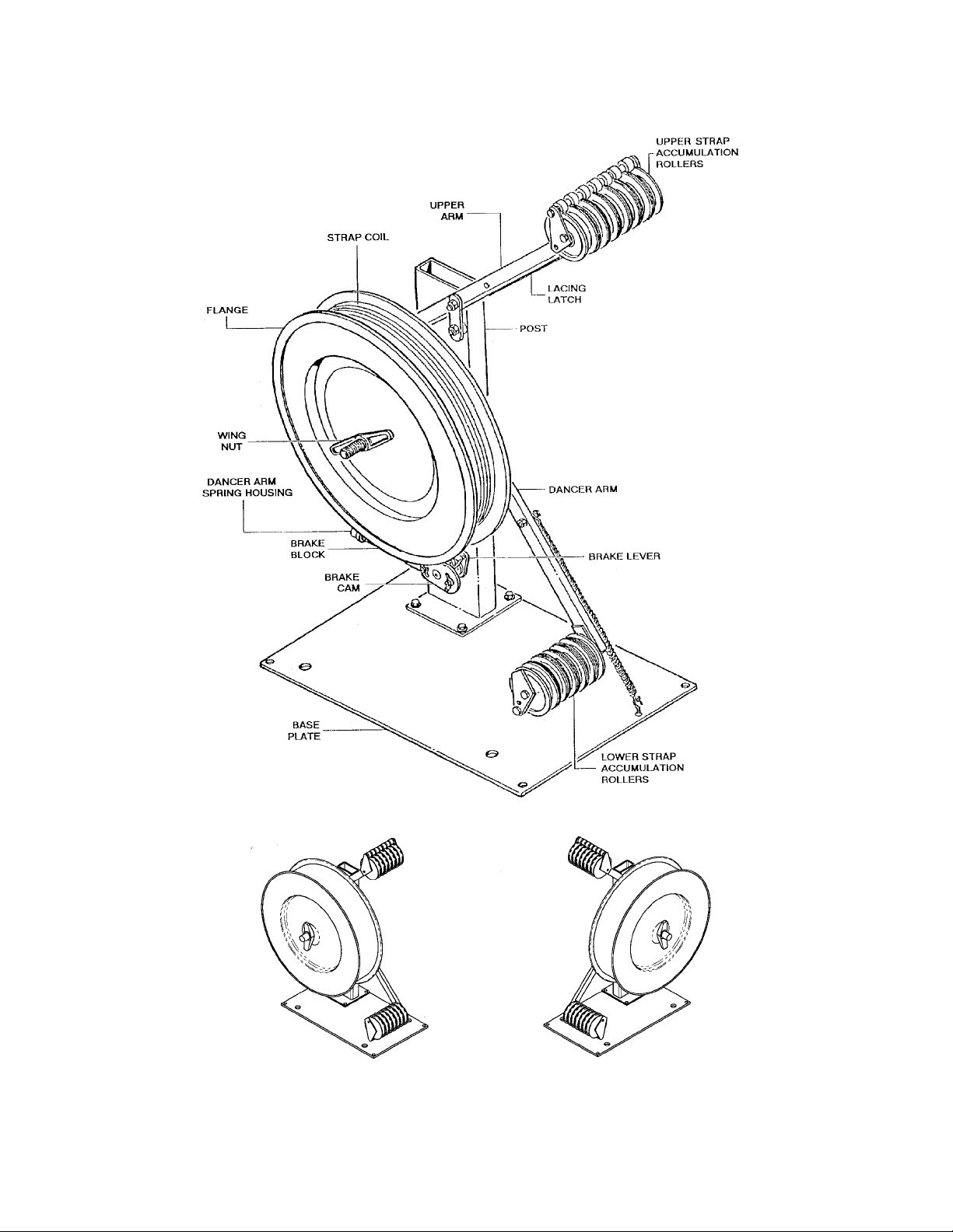
SPECIFICATIONS
MODEL STRAPPING
PSD-109
TYPE WIDTH COIL SIZE
Polyester
or
Polypropylene
Up to 16mm 24"OD x 16"ID x 6"W
4
RIGHT-HAND ORIENTATION LEFT HAND ORIENTATION
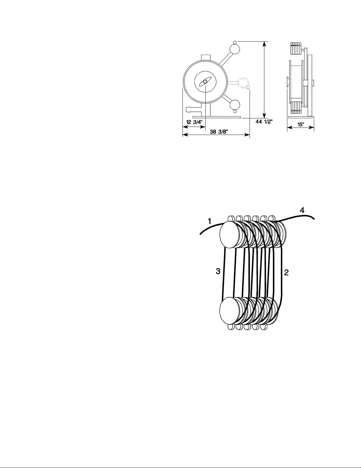
MAJOR COMPONENTS
5
INSTALLATION
The dispenser should be placed at least 4 feet
from the machinery that it will be serving.. The
Options Section contains the optional hardware
required to accommodate the less common
locations relative to the machine. Once
permanent location has been determined, use
the base as a template to transfer the mounting
hole locations to the floor to accept 3/8"
anchors. Securely fasten the dispenser in
place.
COIL LOADING INSTRUCTIONS
There are two methods used to load a coil of strap into the dispenser. The first assumes that
there is no strap in the dispenser and requires hand threading the multi-roller accumulating
system. The second method takes advantage of strap already threaded through the system.
NO STRAP IN THE DISPENSER
1. Remove the wing nut then lift the outer flange
from the dispenser.
2. Swing the lacing latch down from the upper arm.
Raise the dancer arm and hook it onto the latch.
This will release the brake and reduce the
distance between the dancer arm and the upper
arm.
3. Before installing the coil of strap, note the
direction of pay-off of the lead end. The coil
should be placed on the dispenser with the lead
end of hte strap feeding off the top towards the
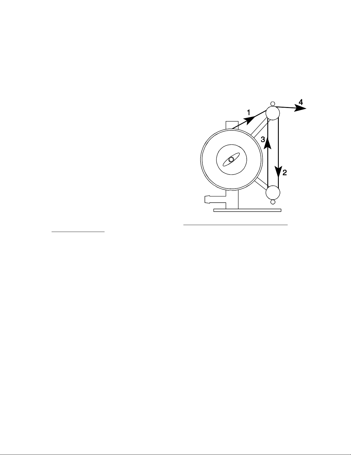
upper roller stack, (1).
4. Leave the crossties and the face blocks intact.
Place new coil on the step of the rear flange and
reinstall the outer reel disc assembly. Snug the wing nut.
5. Cut the crossties on the coil, carefully remove the ties and the face blocks and securely
tighten the wing nut.
6. Make sure there are no twists or kinks in the strap. Feed it around the outermost roller on the
upper roller stack.
7. Direct the lead end down and around the outermost roller on the lower roller stack (2).
6
COIL LOADING INSTRUCTIONS, Continued
8. Guide strap back up and over the next roller on the upper roller stack, (3). Repeat this
process until all the rollers are loaded. The lead end of the strap should terminate at the
innermost upper arm roller, (4).
9. Hold on to the strap lead end and release the dancer arm latch. The spring loaded dancer
arm will return to its lower position and the strap is ready to be inserted into the machine.
Return the lacing latch to its storage position on the
upper arm.
STRAP IN THE DISPENSER
Strap threading can be simplified if the dispenser is
reloaded just before the coil runs out.
1. Re move the strap from the strapping machine and
make sure the dancer arm is in its lowermost
position.
2. Cut the strap at the coil and follow steps 1,3, and 5,
Method One, to load a new coil on the dispenser.
3. Tape the lead end of the new coil to the trailing end
of the old strap and manually draw the new strap
through the roller stacks.
4. Remove and discard the old strap and the tape. Tape must not be allowed to enter the
strapping machine,
5. Insert the new strap into the strapping machine.
DISPENSER OPERATION
As strap is drawn from the dispenser, the dancer arm is raised and the flange brake is released.
The multi-roller design permits the strap coil to accelerate smoothly to full speed and strap is
dispensed. When strap demand is complete, the dancer arm returns to its lowermost position.
The brake is engaged, the strap coil stops rotating and the excess strap is accumulated within
the multi-roller configuration.
7
ADJUSTMENTS
WEAR SAFETY GLASSES WITH SIDE SHIELDS WHICH CONFORM TO ANSI STANDARD
Z87.1. FAILURE TO WEAR SAFETY GLASSES COULD RESULT IN SEVERE PERSONAL
INJURY. PROTECT YOUR EYES. READ GENERAL SAFETY INSTRUCTIONS IN THE FRONT
OF THIS MANUAL
• Only trained people should service machine
• Unless specified, shutoff and lock out all electrical power.
• Follow all service instructions.
• Use Correct tools.
• Never adjust, repair or oil moving machinery
DANCER ARM COMPRESSION SPRING
This adjustment has been factory made and should
not be readjusted. Any additional preloading on this
spring may cause chain or connecting link failure
during operation.
BRAKE BLOCK PRESSURE
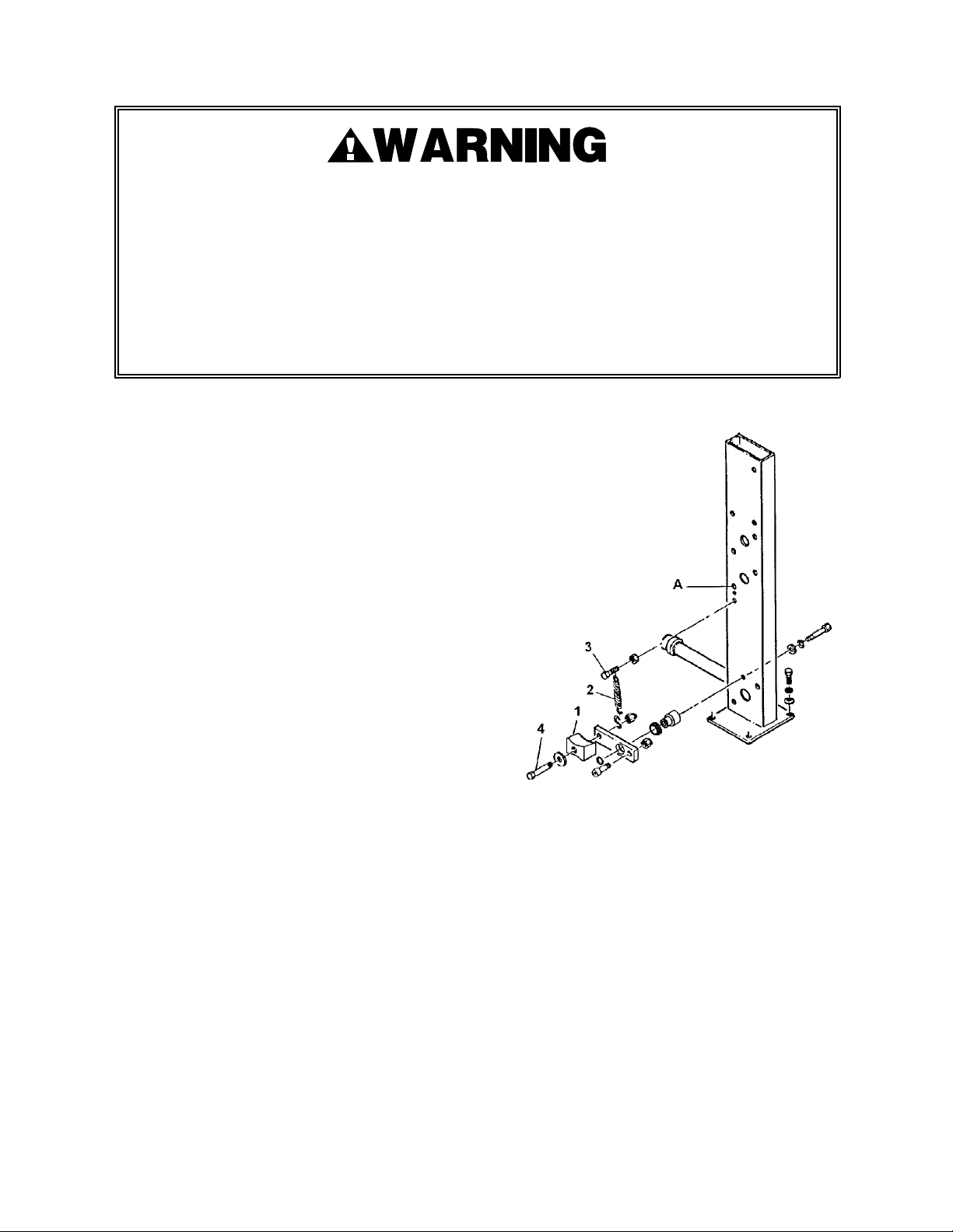
Pressure is applied to the brake block (1) by means of
an extension spring (2) connected between the brake
block mounting screw (4) and a 5/16 hex head cap
screw (3) extending from the dispenser post (A) just
beneath the dispenser shaft mounting hole. At this
upper location are two 5/16-24 tapped holes.
Additional spring tension can be gained by removing
the 5/16 hex head screw and moving it to the upper
hole. Make sure the screw extends no more than 3/4"
and it is securely locked to the post with nut
provided.
BRAKE BLOCK ROTATION
The friction surface on the brake block (1) will eventually wear to a point that proper pressure
gained from the extension spring (2) is no longer possible. When that occurs, loosen the brake
block mounting screw (4) and rotate the block 180 degrees. Make sure the mounting screw has
been securely tightened. When both sides of the brake block are fully worn, replace the block.

8
ADJUSTMENTS, Continued
STRAP ACCUMULATION
The amount of strap retracted from the strapping
machine by the dispenser is dependent upon the
position of the dancer arm when the brake is
engaged.
If the brake engages too near the lower end of the
dancer arm travel, very little strap is retracted and
accumulated. The loops between the roller stacks
and the length of strap between the dispenser and
the strapping machine can become excessively
loose.
Brake engagement too near the upper end of the
dancer arm travel will result in excessive coil
acceleration and high back tension on the strap
entering the strapping machine.
Since proper strap accumulation depends on the
application, the factory setting must be considered
nominal and some fine tuning may be required.
The brake is engaged when the cam follower (1)
on the brake lever (2) is driven in an upward
direction by the cam (3) on the dancer arm shaft
(4). The amount of pre-travel adjusted into the
cam will determine the point at which the brake is
engaged.
To adjust the brake engagement point, loosen the two cam fasteners (5) and reposition the cam
as needed. If more adjustment is needed than is available through use of the slots in the cam,
reposition the fasteners in the adjacent tapped holes provided.
Make sure the cam fasteners are securely tightened to maintain the setting.
NOTE: If the release point s set to occur above the dancer arm latching position, the dispenser
will not be free to turn during the strap threading procedure.

9
PARTS REMOVAL AND REPLACEMENT
WEAR SAFETY GLASSES WITH SIDE SHIELDS WHICH CONFORM TO ANSI STANDARD
Z87.1. FAILURE TO WEAR SAFETY GLASSES COULD RESULT IN SEVERE PERSONAL
INJURY. PROTECT YOUR EYES. READ GENERAL SAFETY INSTRUCTIONS IN THE FRONT
OF THIS MANUAL
• Only trained people should service machine
• Unless specified, shutoff and lock out all electrical power.
• Follow all service instructions.
• Use Correct tools.
• Never adjust, repair or oil moving machinery
BRAKE BLOCK
To remove and replace the brake block:
1. Lift the dancer arm and hang it on the
lacing hatch. This will discharge the
brake.
2. Disconnect the extension spring (1) at the
S-hook (2) on the brake lever (3).
3. Remove the 1/2-20 stop nut (4), the hex
head cap screw (5), the flat washer (6) and
the worn brake block (7) from the brake
lever.
4. Install the brake block and reassemble all
parts. At this point, just snug the stop nut.
5. Turn the brake block so that the rolled
edge of the inner flange will make as much
contact with the brake block as possible.
6. Attach the extension spring to the S-hook.
7. Tighten the stop nut until the brake block
is firmly held between the flat washer and
brake lever.
8. Release the dancer arm and return the lacing latch to its storage position on the upper arm.
9. Readjust the brake block pressure, if needed. Refer to the Adjustments Section for details.

10
PARTS REMOVAL AND REPLACEMENT, Continued
DANCER ARM COMPRESSION SPRING
To remove and replace the dancer arm
compression spring (6):
1. Place dancer arm in its lowest position.
2. Remove the pipe cap (1) from the spring
housing (2).
3. Remove hex nut (3) and the spring stud (5).
This may be difficult to do as thread sealant
was applied during factory assembly.
4. Remove and replace the dancer arm
compression spring. NOTE: Make sure the
chain remains on the brake camshaft
sprocket during this procedure.
5. Apply thread adhesive, Loctite 242 or
equivalent, to the spring stud and
reassemble the spring bushing and hex nut.
6. Tighten the hex nut until the slack is
removed from the chain-then tighten no
further. If the dancer arm compression
spring is overtightened, the chain or the
connecting link may fail during operation.
7. Reinstall the pipe cap.
Failure to install the pipe cap could result in injury to personnel if the chain or connecting
link should fail during operation. A sudden release of dancer arm compression should
propel the spring stud, bushing, etc. from end of the spring housing at high velocity.
Altri manuali per PSD-109
1
Questo manuale è adatto per i seguenti modelli
2
Indice
Altri manuali Signode Distributore


