Snazzi SN1510-A1 Manuale utente

A SERIES
Operang Instrucons
NETWORK RECEIVER BOX
Model No. SN1510-A1
Snazzi*

net•TV |RECEIVER
Contents
Check the Package Contents·········································································································································4
Locating Control and Ports············································································································································5
Hardware Installation······················································································································································7
Viewing the Remote Control········································································································································11
Connect the Transmitter Box·······································································································································14
Use the AV Video Source (only for 8960A5/A7) ·········································································································18
Record Programs··························································································································································19
Play Recorded Files······················································································································································20
Set the Receiver Box····················································································································································22
<< 3>>
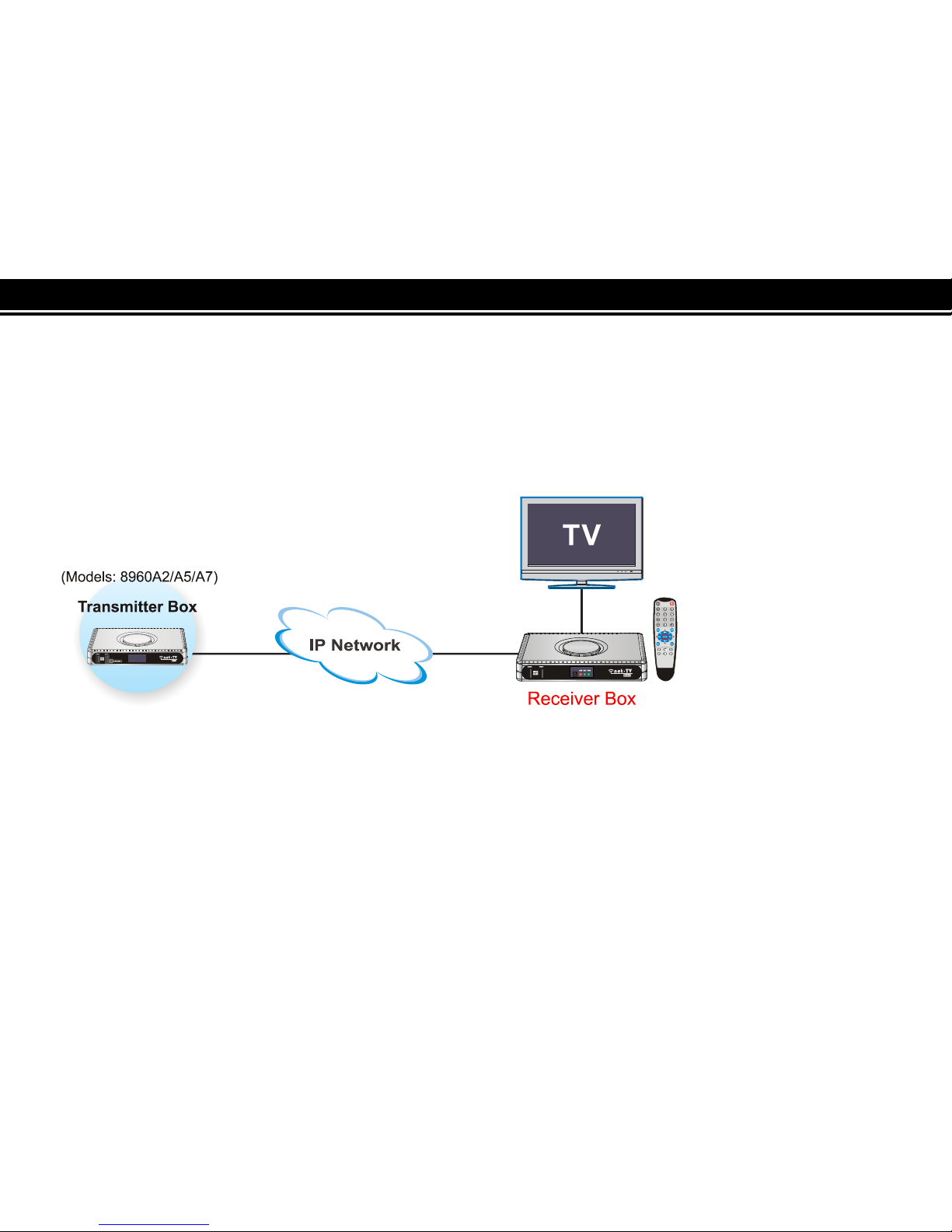
The net-TV Box has two parts: Encoding Transmitter Box (including models PTA-8960A2/8960A5/8960A7)
and this decoding Receiver Box. The Receiver Box must be connected to the Transmitter Box via the network
(LAN or WAN) to enjoy programs.
Ready? Please refer to the following instructions to use net-TV Box.
<< 4>>
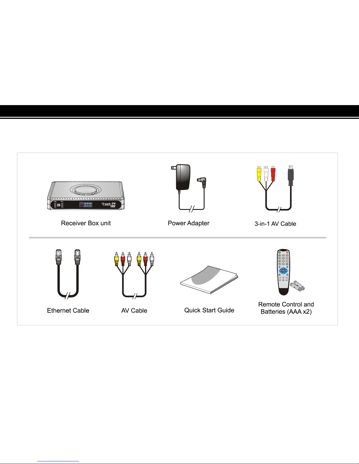
Check the Package Contents
After unpacking, check that if all the following items have been included:
<< 5>>
Locating Control and Ports
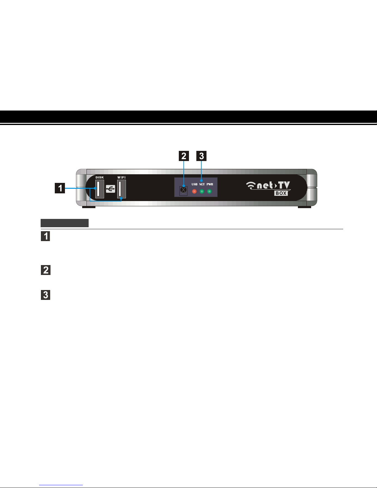
Front Panel
USB Port:
DISK: Connect a USB storage device for record or playback.
WiFi: Connect the specific WiFi wireless USB adapter or 3.5G Modem to access network.
Remote Sensor:
Point remote control here.
Status indicators:
Show the current status of this product.
USB :USB storage indication
NET: Network connection indication
PWR: Power indication.
<< 6>>
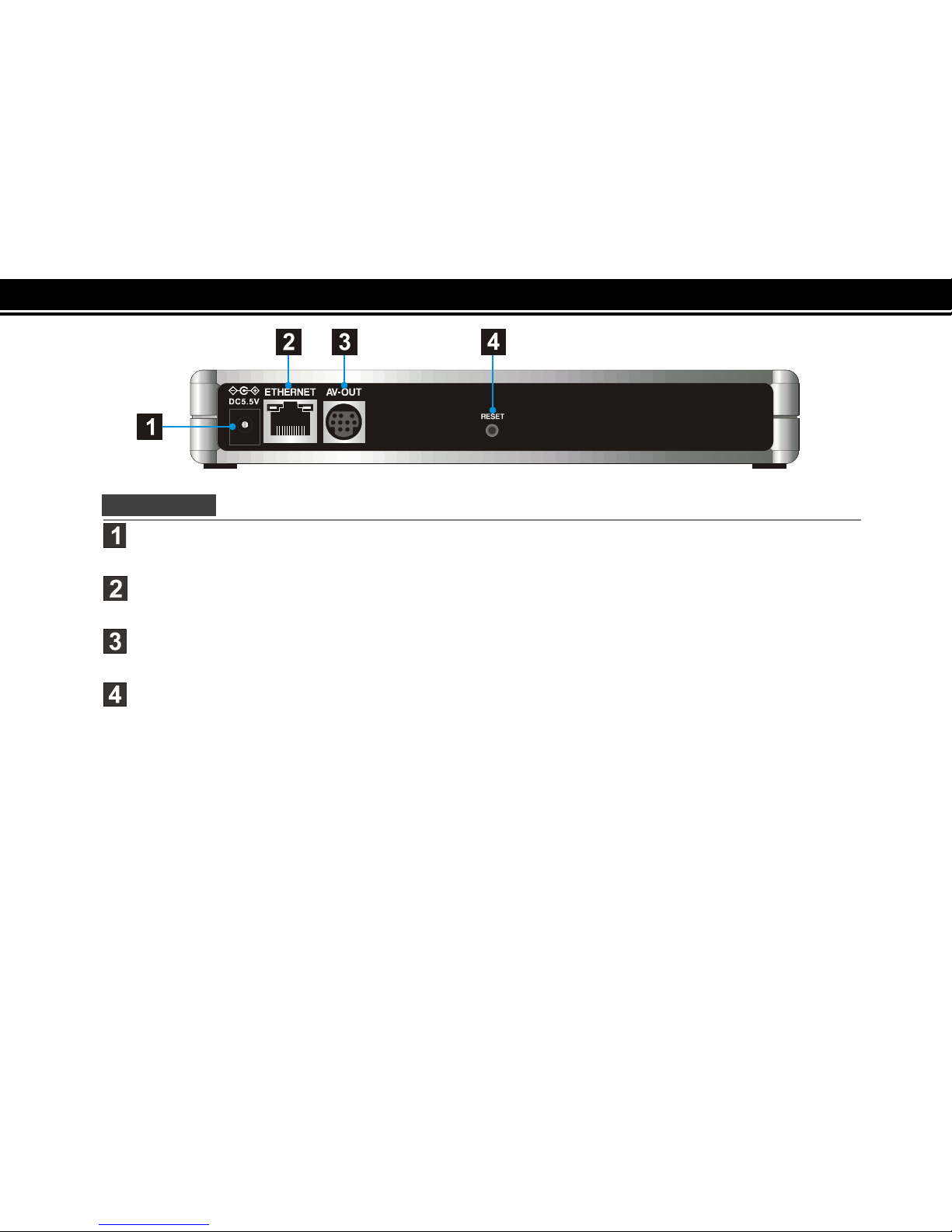
Rear Panel
DC-IN:
Connect the supplied power adapter.
ETHERNET:
Connect a network with an always-on broadband connection.
AV-OUT:
Connect to the A/V input of TV by the supplied 3-in-1 AV cable.
RESET:
Press it with pen-point for three seconds, the box will reset to the default setting.
<< 7>>
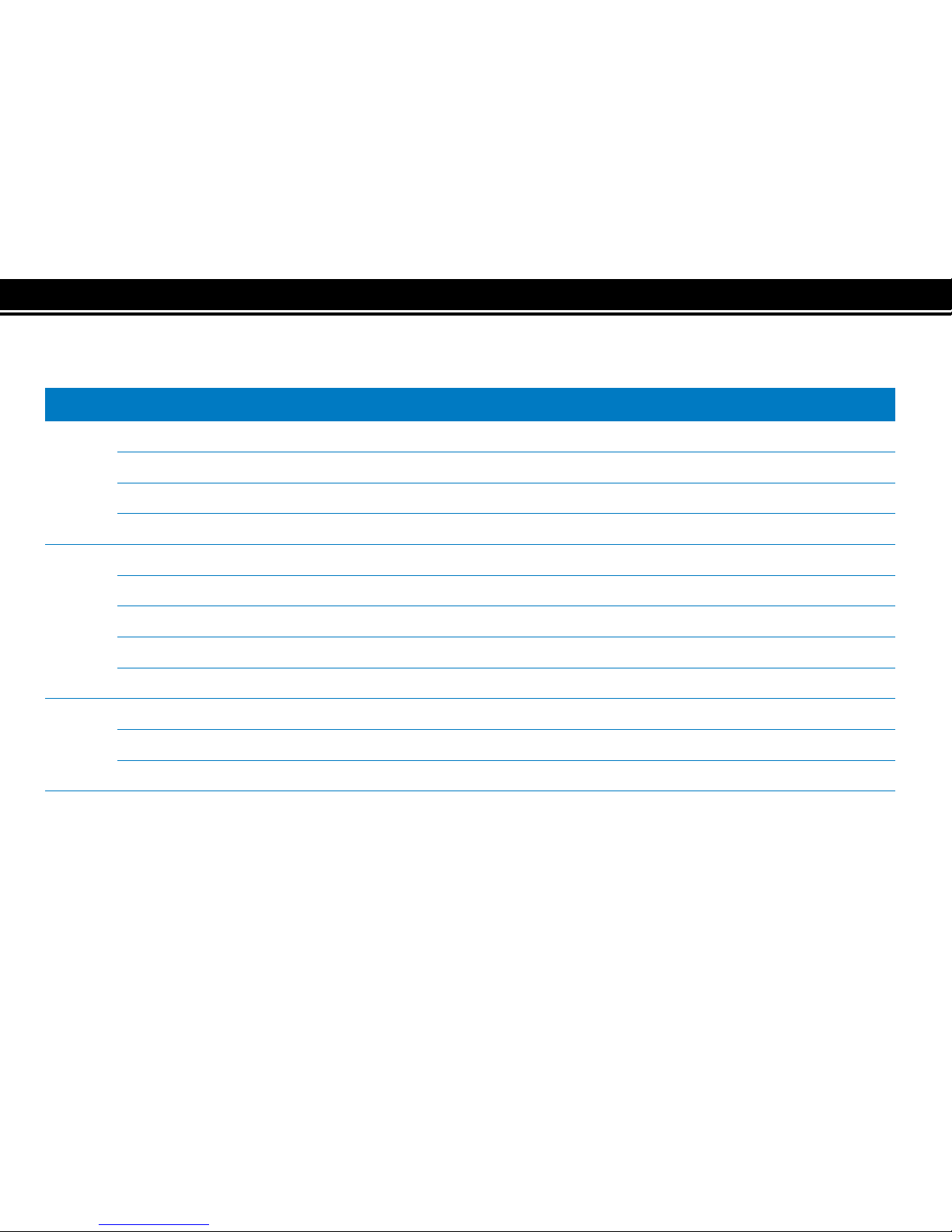
Table 1 The Status Indicators:
The Receiver Box has three status lights on the front to indicate what’s happening.
LED
Indication
Meaning
PWR
●Light off The power of the box is off.
●Dark green static The box is starting up or in standby.
●Light green static The box is operating.
☀
Green flashing
The box is resetting to the factory defaults.
NET
●Light off Both the WAN and LAN connection are not ready, or have failed.
●
Red static LAN functionality is enabled.
☀
Red flashing The box is sending or receiving data over LAN.
●
Green static
Either WAN or WAN+LAN functionality is enabled.
☀
Green flashing The box is sending or receiving data over either WAN or WAN+LAN.
USB
●Light off The USB storage is not being used.
●Red static The USB storage is plugged into the USB port.
☀
Red flashing
Illuminates when data is read from or written to the USB storage.
<< 8>>
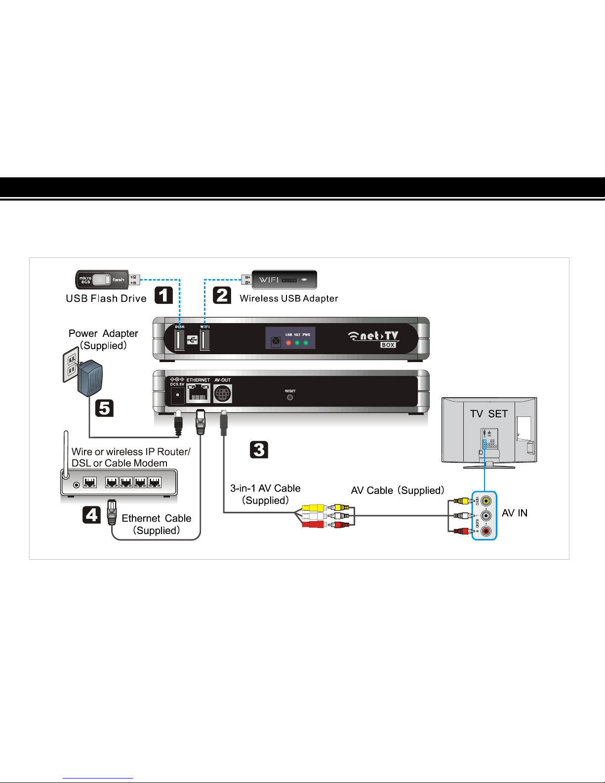
Hardware Installation
Please connect the Receiver Box as the following diagram.
<< 9>>
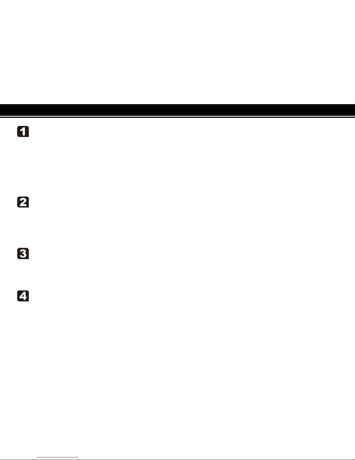
Connect USB Storage
If you want to record the programs or play recorded files, you should plug a USB storage device in the
DISK port at the front panel of the Box.(You can skip the step if you don’t need record)
✍
If the USB storage can’t work when plugged into the DISK port, you can try to plug it into the
3.5G/WiFi port and plug the 3.5G/WiFi device into the DISK port.
Connect 3.5G Modem or WiFi wireless adapter
Plug the 3.5G Modem or WiFi wireless adapter into the 3.5G/WiFi port, and set 3.5G or wiFi as the
network configuration of the Receiver Box (24), and then you can get to internet via the 3.5G or WiFi
wireless network.
Connect Video Output
Use the supplied 3-in-1 AV cable to connect the terminal marked AV-OUT on the Box, then connect
the other end of it to the supplied AV cable, then to the AV IN [VIDEO & L-AUDIO-R] of your TV.
Connect to Your Network
Connect the Receiver Box’s ETHERNET port to the corresponding port on your Modem or Router
using the supplied Ethernet cable.

<< 10 >>
Connect Power Source
Connect the power adapter to the port labeled DC5.5V. Plug the power adapter into an electrical
outlet.
[Note]Remember to place the step at last.
Indice


