
Sony VPL-FX500L Manuale utente

4-191-106-11 (1)
© 2010 Sony Corporation
Data
Projector
Operating Instructions
Before operating the unit, please read this manual and supplied Quick Reference Manual
thoroughly and retain it for future reference.
VPL-FX500L

2Table of Contents
Table of Contents
Overview
Location and Function of Controls .... 3
Main Unit ..................................... 3
Connector Panel ........................... 4
Remote Commander and Control
Panel .......................................... 5
Preparation
Connecting the Projector ................... 8
Connecting a Computer ................ 8
Connecting a Video Equipment ... 9
Connecting an External
Monitor ................................... 10
Projecting/Adjusting an
Image
Projecting an Image ......................... 11
Adjusting the Focus, Size, and
Position of the Projected
image ....................................... 12
Turning Off the Power ................ 13
Adjustments and Settings
Using a Menu
Using a MENU ................................ 14
The Picture Menu ............................. 15
The Screen Menu ............................. 16
The Function Menu .......................... 18
The Operation Menu ........................ 19
The Connection/Power Menu .......... 20
The Installation Menu ...................... 21
The Information Menu ..................... 22
Network
Using Network Features ...................23
Displaying the Control Window of
the Projector with a Web
Browser ...................................23
Confirming the Information
regarding the Projector ............24
Operating the Projector from a
Computer .................................24
Using the Mail Report
Function ...................................24
Others
Indicators ..........................................26
Messages List ...................................27
Troubleshooting ................................28
Replacing the Lamp ..........................30
Replacing the Air Filter
Cartridges ......................................32
Attaching/Removing the Projection
Lens ...............................................34
Attaching .....................................34
Removing ....................................38
Specifications ...................................39
Projection Distance and Lens Shift
Range ............................................45
Dimensions .......................................49
Index .................................................52
3
Location and Function of Controls
Overview
BOverview
Location and Function of Controls
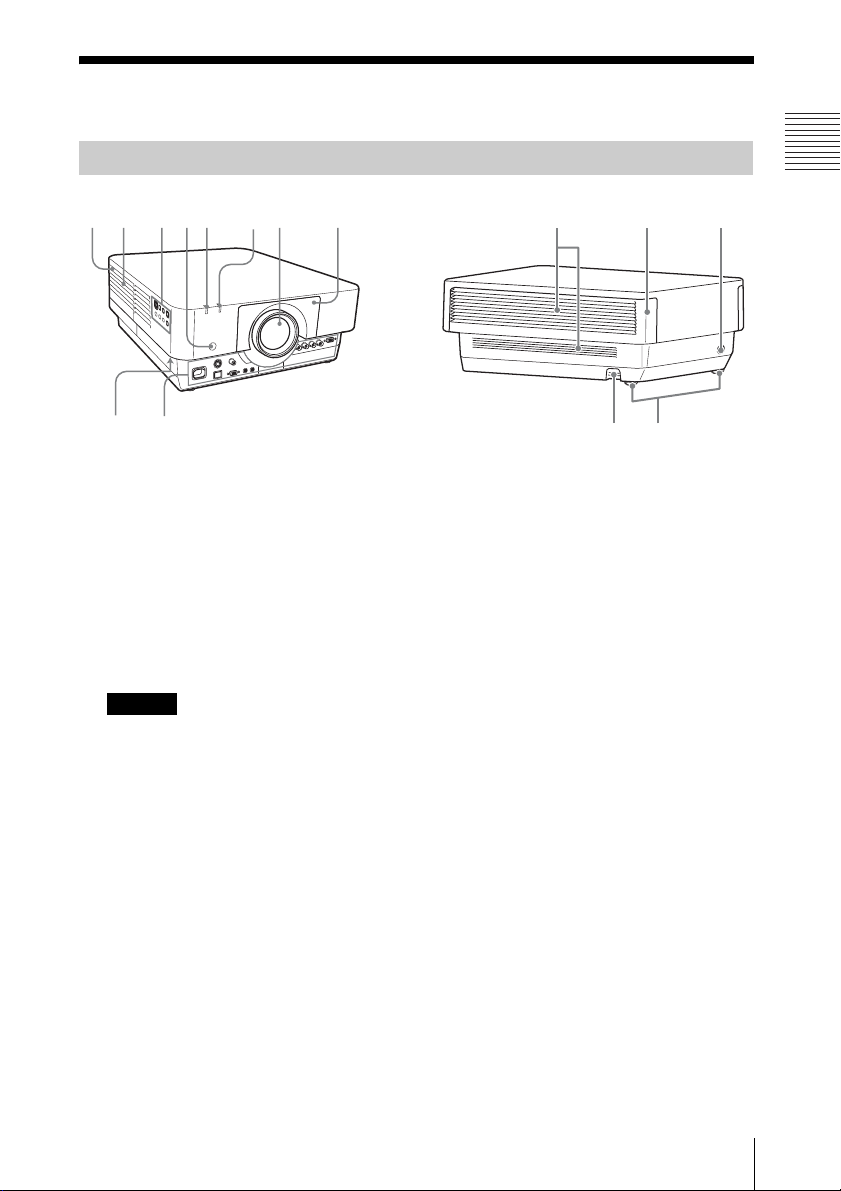
aLens (not supplied) (page 34)
bFront panel (page 34)
cLamp cover (page 30)
dAir filter cover (page 32)
eVentilation holes (intake)
fVentilation holes (exhaust)
Do not place anything near the ventilation
holes as this may cause internal heat
buildup. Do not place your hand near the
ventilation holes and the circumference as
this may cause injury.
gON/STANDBY indicator
(page 26)
hLAMP/COVER indicator
(page 26)
iControl panel (page 5)
jConnector panel (page 4)
kRemote control detectors
lAdjusters (page 12)
mSecurity lock
Connects to an optional security cable
manufactured by Kensington.
For details, visit Kensington’s web site.
http://www.kensington.com/
nSecurity bar
Connects to a commercially available
security chain or wire.
Main Unit
69qa3
q;
712
8
qd
54
q
s
qf
qa
Caution
4Location and Function of Controls
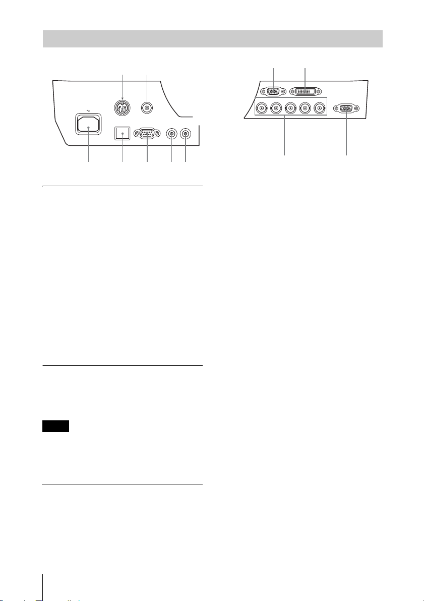
Input (pages 8, 9)
aINPUT A
Video: RGB/YPBPRinput connector
(RGB HD VD/YPBPR)
bINPUT B
Video: RGB input connector (RGB)
cINPUT C
Video: DVI-D input connector (DVI-D)
dS VIDEO (S VIDEO IN)
Video: S video input connector
eVIDEO (VIDEO IN)
Video: Video input connector
Output (page 10)
fOUTPUT
Video: Monitor output connector
(MONITOR)
This connector outputs the image. Output as a
computer signal input from the RGB input
connector or a video signal input from the
YPBPRinput connector.
Others
gRS-232C connector
RS-232C compatible control connector
hLAN connector (page 23)
iCONTROL S input connector
(DC power supply) (CONTROL S
IN PLUG IN POWER)
Connects to the CONTROL S output
connector on the supplied Remote
Commander with a connecting cable
(stereo mini plug (not supplied)) when
using it as a wired Remote Commander.
You do not need to install batteries in the
Remote Commander, as the power is
supplied from this connector.
jCONTROL S output connector
(CONTROL S OUT)
For coupling control of multiple
projectors with the wired Remote
Commander.
kAC IN (∼) socket
Connects the supplied AC power cord.
Connector Panel
S VIDEO IN
LAN RS-232C CONTROL S
VIDEO IN
INPUT B RGB INPUT C DVI-D
PLUG INPOWER
IN OUT
R/PRG/Y HD VD OUTPUT
MONITOR
B/PB
INPUT A
4
q
a
879q
;
523
16
Note
5
Location and Function of Controls
Overview
Remote Commander
Control Panel
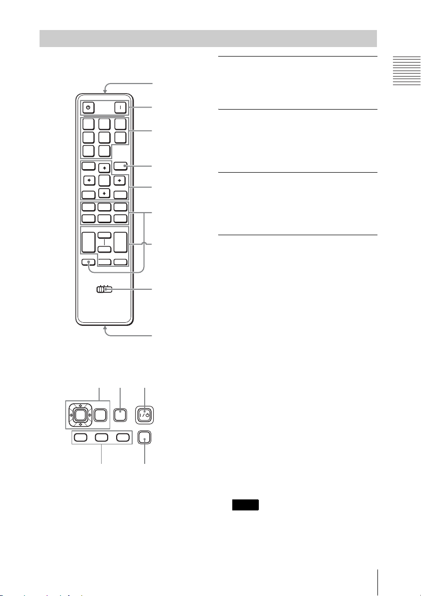
aTurning on the power/Going to
standby mode
?(On) key
1(Standby) key
bSelecting an input signal
(page 11)
INPUT key (main unit)
Direct input select keys (Remote
Commander)
cOperating a menu (page 14)
ENTER /V/v/B/b(arrow) keys
MENU key
RETURN key
RESET key
dAdjusting the image (page 12)
FOCUS key
Use this key when attaching the power
focus lens.
ZOOM key
Use this key when attaching the power
zoom lens.
SHIFT key
ASPECT key (pages 16, 17)
Changes the aspect ratio of the projected
image.
KEYSTONE key
Adjusts the vertical trapezoidal
distortion of the image manually. When
you press this key, the Keystone menu is
displayed. Use the arrow keys (V/v/B/
b) for adjustment.
PATTERN key
APA (Auto Pixel Alignment) key
Automatically adjusts a picture to its
clearest while a signal is input from a
computer. You can cancel the adjustment
by pressing the APA key again while
adjusting.
*Use this key when inputing a computer
signal via the RGB input connector.
Remote Commander and Control Panel
ONSTANDBY
INPUT
ABC
DE F
VIDEO
MENU
ECO
MODE
S
VIDEO
ENTER
RESETRETURN
SHIFTZOOMFOCUS
ASPECT PATTERN
KEY-
STONE
D ZOOM VOLUME
MUTING
PIC
AUDIO
+
–
+
–
TWIN FREEZEAPA
1 2 3
ID MODE
1
7
2
6
3
4
8
9
5
ECO
MODE
ENTER
MENU
SHIFT ZOOM
FOCUS
INPUT
312
46
Note

6Location and Function of Controls
eUsing various functions during
projecting
D ZOOM (Digital Zoom) +/– key*1
Enlarges a portion of the image while
projecting.
1Press the D ZOOM + key to display
the digital zoom icon on the projected
image.
2Press the V/v/B/bkeys to move the
digital zoom icon to the point on the
image you wish to enlarge.
3Press the D ZOOM + key or the D
ZOOM – key repeatedly to change the
enlargement ratio. The image can be
enlarged up to 4 times.
Press the RESET key to restore the
previous image.
MUTING key
PIC: Cuts off the image. Press again to
restore the image.
AUDIO: This function is not provided
in this projector.
VOLUME +/– key
This function is not provided in this
projector.
TWIN (double-window) key
This function is not provided in this
projector.
FREEZE key*2
Pauses a projected image. Press again to
restore the image.
*1: Use this key when inputting a
computer signal. But it may not be
enabled, depending on the resolution
of the input signal.
*2: Use this key when inputting a
computer signal.
fSetting the energy–saving mode
easily
ECO MODE key
Energy-saving mode can be set easily,
using a Remote Commander. Energy-
saving mode consists of “Lamp Mode,”
“Power Saving Mode” and “Standby
Mode.”
1Press the ECO MODE key to display
the ECO Mode menu.
2Press the V/vkey or ECO MODE key
to select ECO or User mode.
ECO: Sets each mode to the optimum
energy-saving value.
Lamp Mode: Standard
Power Saving Mode: Standby
Standby Mode: Low
(go to step 6)
User: Sets each item of the energy-
saving mode menu as you desire
(go to step 3).
3Select “User” then press the bkey.
The setting items appear.
4Press the V/vkey to select the ECO
Mode item then press the bkey or the
ENTER key.
5Press the V/vkey to select the setting
value.
6Press the RETURN key to restore the
previous image.
For details on ECO Mode settings, see
“Lamp Mode” (page 18) on the Function
menu and “Standby Mode” (page 20)
and “Power Saving Mode” (page 20) on
the Connection/Power menu.
Others
gInfrared transmitter
hID MODE 1/2/3 switch (page 19)
Sets an ID mode of the Remote
Commander. If you assign a different ID
number to each projector when multiple
projectors are used, you can control only
the projector with the same ID mode as
that of the Remote Commander.
Notes
ECO
User
Sel Back
ECO Mode
ECO Mode Menu
Lamp Mode Standard
Power Saving Mode Off
Standby Mode Standard
Sel Back
User
Set

7
Location and Function of Controls
Overview
iCONTROL S output connector
Connects to the CONTROL S input
connector on the projector with a
connecting cable (stereo mini plug (not
supplied)) when using the Remote
Commander as a wired one.
You do not need to install batteries in the
Remote Commander, as the power is
supplied from the projector.
About Remote Commander operation
• Make sure that nothing obstructs the
infrared beam between the Remote
Commander and the remote control
detector on the projector. Direct the
Remote Commander toward the remote
control detector.
• The operation range is limited. The shorter
the distance between the Remote
Commander and the projector is, the wider
the angle within which the Remote
Commander can control the projector
becomes.
8Connecting the Projector
BPreparation
Connecting the Projector
• Use the proper cables for each connection.
• Insert the cable plugs firmly; Loose connections may reduce performance of picture signals or
cause a malfunction. When pulling out a cable, be sure to grip it by the plug, not the cable itself.
• For more information, refer also to the instruction manuals of the equipment you are connecting.
Connection with a computer is explained for each input signal.
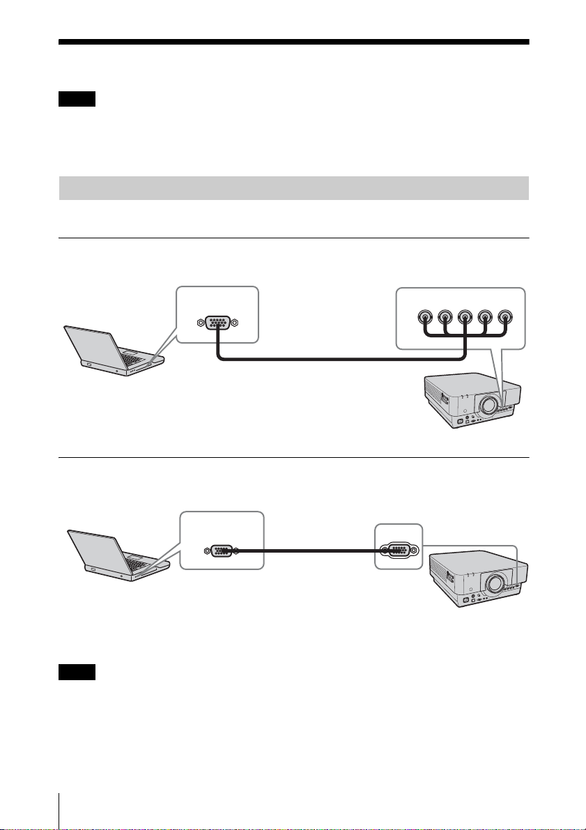
INPUT A
For connection when there is some distance between a computer and the projector.
INPUT B
For connecting a computer with an RGB output connector.
• It is recommended that you set the resolution of your computer to 1024 × 768 pixels for the
external monitor.
• To connect a Macintosh computer equipped with a video output connector of a type having two
rows of pins, use a commercially available plug adaptor.
Notes
Connecting a Computer
R/PRG/Y B/PBHD VD
INPUT A
Mini D-sub 15-pin – BNC cable
(not supplied)
RGB output
connector
Computer
Notes
INPUT B RGB
Mini D-sub 15-pin
cable (not supplied)
RGB output
connector
Computer

9
Connecting the Projector
Preparation
INPUT C
For connecting a computer with a DVI-D output connector.
Connections with a VHS video deck, DVD player, or BD player are explained for each input
signal.
S VIDEO IN
For connecting video equipment with an S-video output connector.
VIDEO IN
For connecting video equipment with a video output connector.
Connecting a Video Equipment
INPUT C DVI-D
DVI-D cable
(not supplied)
DVI-D output
connector
Computer
S video cable (not supplied)
S video output
connector
Video equipment
Video – BNC cable
(not supplied)
Video output
connector
Video equipment
10 Connecting the Projector
INPUT A
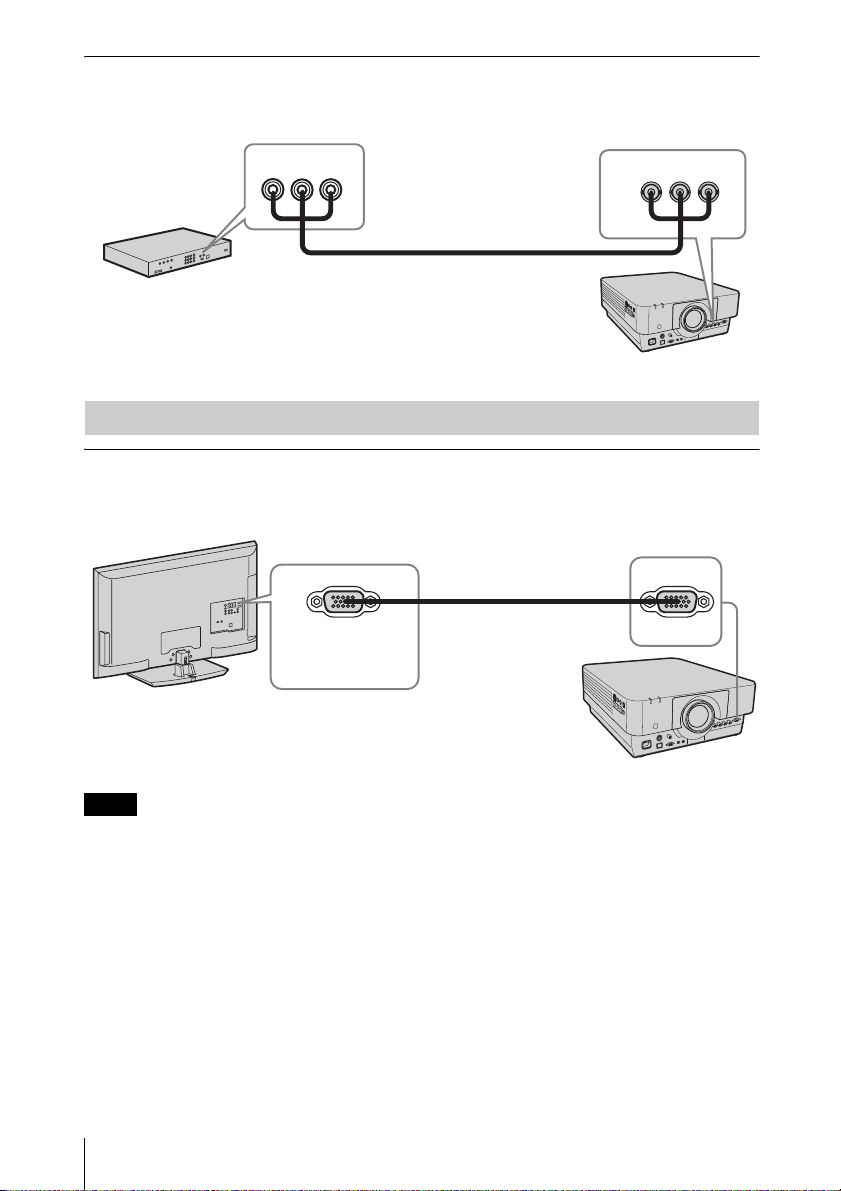
For connection when there is some long distance between the video equipment and projector.
OUTPUT
Projected images can be output to display equipment such as a monitor.
Output only as a computer signal input from the RGB input connector or a video signal input from
the YPBPRinput connector.
R/PRG/Y B/PB
INPUT A
Component – BNC cable (not supplied)
Video equipment
YPBPRoutput
connector
Connecting an External Monitor
Note
OUTPUT
MONITOR
Mini D-sub 15-pin cable
(not supplied)
RGB input
connector
Display equipment
Altri manuali per VPL-FX500L
4
Indice
Altri manuali Sony Proiettore

Sony
Sony VPD-LE100 Manuale utente

Sony
Sony IFB-X2000E Manuale utente

Sony
Sony VPL-CH355 Manuale utente

Sony
Sony KP-53XBR4CT Manuale utente

Sony
Sony VPL-PS10 Manuale utente

Sony
Sony VPL-CS10 Manuale utente

Sony
Sony VPL-X600U Mk II Manuale utente

Sony
Sony SRX-R515P Manuale utente

Sony
Sony VPL-SX125 Manuale utente

Sony
Sony SRX-T105 Manuale utente

Sony
Sony VPL-CX76 Manuale utente

Sony
Sony VPL-FX30 Manuale utente

Sony
Sony VPL-FHZ61 Manuale utente

Sony
Sony VPL-PX21 Manuale utente

Sony
Sony HDMI VPL-FE40 Manuale utente

Sony
Sony VPLFH31/B Manuale utente

Sony
Sony VPL-CX76 Manuale utente

Sony
Sony VPL-FHZ120L Manuale utente

Sony
Sony VPL-FH31 Manuale di servizio

Sony
Sony Superbright VPL-PX40 Manuale utente


