Sorotec COMPACT 0605 Manuale utente

SOROTEC GmbH
Withig 12
77836 Rheinmünster
Tel.: +49 (0) 7227-994255-0
Fax: +49 (0) 7227-994255-9
E-Mail: [email protected]
Web: www.sorotec.de
Assembly instructions
CNC portal milling machine kit
Basic-Line
Version 2.3.3
MPF.BLxxxx.01.B

Page 1/26
Assembly instructions
Basic-Line kit
www.sorotec.de V 2.3.3
Technical specications
Basic-Line 0605 0607 1005 1007
Travel X: 650 mm
Y: 530 mm
Z: 140 mm
X: 650 mm
Y: 730 mm
Z: 140 mm
X: 1050 mm
Y: 530 mm
Z: 140 mm
X: 1050 mm
Y: 730 mm
Z: 140 mm
Clearance
under portal
180 mm 180 mm 180 mm 180 mm
Clamping area X: 840 mm
Y: 530 mm
X: 840 mm
Y: 730 mm
X: 1240 mm
Y: 530 mm
X: 1240 mm
Y: 730 mm
Outer dimensions L: 950 mm
B: 790 mm
H: 820 mm
L: 950 mm
B: 990 mm
H: 820 mm
L: 1350 mm
B: 790 mm
H: 820 mm
L: 1350 mm
B: 990 mm
H: 820 mm
Ball screw spindles
Tolerance class T07
X: 16 x 10 mm
Y: 16 x 10 mm
Z: 16 x 5 mm
X: 16 x 10 mm
Y: 16 x 10 mm
Z: 16 x 5 mm
X: 16 x 10 mm
Y: 16 x 10 mm
Z: 16 x 5 mm
X: 16 x 10 mm
Y: 16 x 10 mm
Z: 16 x 5 mm
Weight without
accessories
approx. 46 kg approx. 52 kg approx. 50 kg approx. 57 kg
© 2023 Sorotec GmbH
Reproduction, duplication or translation, also in extracts, without the written approval of
Sorotec GmbH is not permitted. All rights under the Copyright Act remain the
Sorotec GmbH expressly reserved.
Technical changes reserved.
Made in Germany.

Page 2/26
Assembly instructions
Basic-Line kit
www.sorotec.de V 2.3.3
Introduction
Congratulations on the purchase of our kit for a
Basic-Line CNC portal milling machine. We recom-
mend reading through these instructions completely
before assembly and then assembling the kit step by
step as described.
Required tools
The following tools and aids must or should be avai-
lable during assembly:
• Common hand tools, such as Allen keys,
screwdrivers, plastic hammers, etc.
• Work surface as at as possible in the size of
the base frame
• Flat or stop angle, at least
• 300 mm long in tolerance class 1 or better
• Dial indicator with stand / holder
• Torque wrench from 6 Nm up to
• at least 25 Nm1)
1) In order to avoid warping due to screws tightened
unevenly, the use of a torque wrench for load-bearing
screws M5 to M8 is recommended. By observing the
prescribed tightening torque also prevents unwanted
loosening during later operation of the machine.
Optional accessories
The fully assembled machine can be supplemented
and adapted to your requirements with optional ac-
cessories. In the Sorotec shop you will nd:
• Performance Kit 2)
• Milling spindles
• Electrical installation kit
• Control electronics
• Control software
• T-slot plate
• Vacuum table
• Minimum quantity lubrication
Caution!
Only carry out the work if you are familiar with the
necessary actions and suitable tools are available.
Sorotec GmbH assumes no liability for damage to
property or personal injury occurring during assem-
bly or operation of the CNC portal milling machine!
General information
Please assemble the kit as carefully and precisely
as possible - the accuracy of the nished machine
does not only depend on the quality of the delivered
components, but also to a high degree on the correct
assembly and exact alignment. Before assembly, all
components must be checked for burrs and rewor-
ked if necessary.
2) recommended for processing non-ferrous metals

Infosheet Measure Screws
SOROTEC GmbH Tel.: +49 (0) 7 7-994 55-0
Withig 1 Fax: +49 (0) 7 7-994 55-9
77836 Rheinmünster E-Mail: sorotec@sorotec.de Version 1.0 Juli 0 0
Dimensions
Screw sizes are always given in the form of "diameter x length". In the case of metric screws, the diameter is
given by an M. Wood, sheet metal or plastic screws are not specially marked in the dimensioning. The unit of
measurement mm is usually not specified.
Examples:
M4 x 40 - metric screw with M4 thread and 40 mm length
3 x 5 - wood screw 3 mm in diameter and 5 mm in length
Web: www.sorotec.de
Diameter
Measurements are always made with the vernier caliper and on the
outside of the thread. To prevent the cutting edges of the measuring
jaws from slipping into the thread grooves, the screw is placed
lengthways between the jaws.
Length
Everything that disappears in the material is part of the
length of a screw. This means that measurements are taken
- ideally with the depth gauge of the caliper - from the
underside of the screw head to the end of the screw. Any
parts without a thread are also part of the length.
Exception countersunk screw
Because the head of the countersunk screw disappears
into the material, the head height here is part of the
length. So the length is measured over everything. But
really: Only with the countersunk screw!

Page 3/26
Assembly instructions
Basic-Line kit
www.sorotec.de V 2.3.3
Scope of delivery
Illustration Description Number
End plate Y on the left
BL.FT.007.01 1
End plate Y on the right
BL.FT.008.01 1
Stop plate Z
BL.FT.013.01 1
Drive X:
xed bearing 4F
CL.ZAN.FL16.H
Ball screw 4S
see page 6
Recirc. ball nut 4K
readily mounted on ball screw
oating bearing 4L
BL.FT.017.01 and
AL.ZAN.LA6000RS
1
1
1
1
Drive Y:
xed bearing 5F
CL.ZAN.FL16.H
Ball screw 5S
see page 6
Recirc. ball nut 5K
readily mounted on ball screw
oating bearing 5L
CL.ZAN.LL16.H
1
1
1
1
Drive Z:
xed bearing 6F
CL.ZAN.FL16.H
Ball screw 6S
ZAN.NTS.KGS1605.0270.M
Recirc. ball nut 6K
readily mounted on ball screw
1
1
1
Stieners Z:
left 7L / right 7R
BL.FT.022.01
2
1
2
3
4
5
6
7
Illustration Description Number
Base plate Z
BL.FT.012.01 1
Flange bracket X
BL.FT.018.01 1
Flange bracket Y
BL.FT.019.01 1
Flange bracket Z
BL.FT.020.01 1
Flange plate
BL.FT.016.01 1
Device base
(self-adhesive)
AL.EZB.0109
7
Claw clutch
MZK.080.100.V25 3
Carriage
ZFW.NTS.HGH20CA
5
(7)
Linear rail X
see page 6 2
8
9
10
11
12
13
14
15
16

Page 4/26
Assembly instructions
Basic-Line kit
www.sorotec.de V 2.3.3
Illustration Description Number
Linear rail Y
see page 6 2
Linear rail Z
(300 mm lg.)
BL.ZFS.HGR20R.0300
1
Motor ange Z
BL.FT.011.01 1
Plate Z
BL.FT.010.01 1
Portal beam
(preassembled)
see page 6
1
Portal beam
see page 6 1
Portal cheek:
left 23L BL.FT.005.01
right 23R BL.FT.004.01
1
1
Prole 10 45 x 90 light
see page 6
3
(4)
Prole 10 45 x 90
heavy (819 mm lg.)
see page 6
2
17
18
19
20
21
22
23
24
25
Illustration Description Number
Prole 5 20 x 20
BL.PR.0520201N.0372 2
Reference switch
with shim
EZB.T1 / AL.IS.001
3
Switch carrier X
CL.FT.013.01 1
Switch carrier Y
BL.FT.021.01 1
Sled Y
BL.FT.009.01 1
Face plate in the back
see page 6 1
Front plate
see page 6 1
Angle 20 x 20
BL.PR.W.052020
including cover
5
Angle 40 x 40
AL.PR.WS.084040
including cover
6
26
27
28
29
31
32
33
34
35

Page 5/26
Assembly instructions
Basic-Line kit
www.sorotec.de V 2.3.3
Illustration Description Number
Angle 45 x 45
AL.PR.WS.104545
8
(12)
Drag chain holder
CL.FT.032.01 1
Tapered grease nipple
M6 x 1
ZB.HI.SN008
2
Grease nipple 90°
M6 x 1
ZB.HI.SN003
3
Cylinder head screw DIN 912
M3 x 14 A1 MED.SMZ8.8V.03.014
M3 x 16 A2 MED.SMZ8.8V.03.016
M4 x 16 B1 MED.SMZ8.8V.04.016
M4 x 20 B2 MED.SMZ8.8V.04.020
M4 x 25 B3 MED.SMZ8.8V.04.025
M5 x 12 C1 MED.SMZ8.8V.05.012
M5 x 14 C2 MED.SMZ8.8V.05.014
M5 x 16 C3 MED.SMZ8.8V.05.016
M5 x 18 C4 MED.SMZ8.8V.05.018
M5 x 20 C5 MED.SMZ8.8V.05.020
M5 x 22 C6 MED.SMZ8.8V.05.022
M5 x 25 C7 MED.SMZ8.8V.05.025
M6 x 14 D1 MED.SMZ8.8V.06.014
M6 x 35 D2 MED.SMZ8.8V.06.035
M6 x 50 D3 MED.SMZ8.8V.06.050
Sliding block 5 M5
3D.PR.NS.05M5S
Hammer nut
Slot 8 M5 G1 AL.PR.HM.08M5.017
Slot 8 M6 G2 AL.PR.HM.08M6.017
Slot 10 M5 H1 AL.PR.HM.10M5.030
Slot 10 M6 H2 AL.PR.HM.10M6.030
Slot 10 M8 H3 AL.PR.HM.10M8.030
36
37
SN
SM
F1
Illustration Description Number
Hammer screw
Slot 10 M8 x 20 J
enclosed with angle
Flat headed screw ISO 7380
M5 x 8 K1 MED.SMF10.9.05.008
M5 x 20 K2 MED.SMF10.9.05.020
M6 x 16 K3 MED.SMF10.9.06.016
M6 x 25 K4 MED.SMF10.9.06.025
M8 x 16 K5 MED.SMF10.9.08.016
M12 x 30 K6 MED.SMF10.9.12.030
Mounting bracket
drag chain
CL.PR.BW.604020
1
Cylinder head screw DIN 6912
M5 x 10 L1 MED.SMZNK8.8V.05.010
M5 x 16 L2 MED.SMZNK8.8V.05.016
M6 x 40 M1 MED.SMZNK8.8V.06.040
M8 x 20 N1 MED.SMZNK8.8V.08.020
Nut DIN 934
M3 OMED.SMU0.8V.03
M4 PMED.SMU0.8V.04
Flange nut DIN 6923
M8 Q
enclosed with angle
Washer DIN 125
3,2 UMED.SUS.V.03
8,4 XMED.SUS.V.08
Dowel pin hard DIN 6325
5 x 18 mm Z
AL.ZS.05.18
38

Page 6/26
Assembly instructions
Basic-Line kit
www.sorotec.de V 2.3.3
Order numbers of size-dependent parts
Maschine
Bezeichnung BL 0605 BL 0607 BL 1005 BL 1007
4S Ball screw X ZAN.NTS.KGS1610.0800.M ZAN.NTS.KGS1610.0800.M ZAN.NTS.KGS1610.1200.M ZAN.NTS.KGS1610.1200.M
5S Ball screw Y ZAN.NTS.KGS1610.0650.M ZAN.NTS.KGS1610.0850.M ZAN.NTS.KGS1610.0650.M ZAN.NTS.KGS1610.0850.M
16 Linear rail X BL.ZFS.HGR20R.0817.BL BL.ZFS.HGR20R.0817.BL BL.ZFS.HGR20R.1217.BL BL.ZFS.HGR20R.1217.BL
17 Linear rail Y BL.ZFS.HGR20R.0622.BL BL.ZFS.HGR20R.0822.BL BL.ZFS.HGR20R.0622.BL BL.ZFS.HGR20R.0822.BL
21 Portal beam BL.FT.023.01 BL.FT.028.01 BL.FT.023.01 BL.FT.028.01
22 Portal beam BL.FT.003.01 BL.FT.024.01 BL.FT.003.01 BL.FT.024.01
24 Prole 10 45 x 90 light BL.PR.104590L.0395 BL.PR.104590L.0595 BL.PR.104590L.0395 BL.PR.104590L.0595
25 Prole 10 45 x 90
heavy
BL.PR.104590S.0819 BL.PR.104590S.0819 BL.PR.104590S.1219 BL.PR.104590S.1219
32 Face plate back BL.FT.001.01 BL.FT.025.01 BL.FT.001.01 BL.FT.025.01
33 Face plate front BL.FT.002.01 BL.FT.026.01 BL.FT.002.01 BL.FT.026.01

Infosheet spindle bearings
SOROTEC GmbH Tel.: +49 (0) 7227 994255 0
Withig 12 Fax: +49 (0) 7227 994255 9
77836 Rheinmünster E Mail: sorotec@sorotec.de Version 1.0 März 2023
Floating bearings are not "loose bearings"
When storing a shaft in a machine, the thermal linear expansion must always be taken into account in the
design. In the case of a ball screw made of high alloy steel, for example, with a length of 0.1 ... 0.2 mm per
meter per 10 Kelvin temperature difference, this is quite considerable the additional tenths have to go
somewhere.
If the roller bearings were to be firmly connected at the ends both to the shaft and to the surrounding housing,
considerable axial stress would quickly arise as a result of thermal expansion. The bearings would be severely
overloaded and would wear out after a short time; Gradually louder, grinding rolling noises are the alarm signal
for bearing damage at the end.
Web: www.sorotec.de
Conflicting requirements
For this reason, the fit between the bearing seat on the shaft and
the inner ring of the bearing as well as that between the outer ring
and the bore in the housing is very tight on the fixed bearing.
Great forces may be required for assembly (plastic hammer, if
necessary driving sleeve for the inner ring), the use of heat and/or
cold to expand or shrink the components can also be helpful. In
any case, use oil!
At the floating bearing, a firm clamping should only guarantee the
guidance of the shaft radially (so that it does not "slack around"),
but it should be movable in the longitudinal direction to allow
thermal expansion without the build up of tension forces. The
mobility can take place either between the shaft and the inner ring
of the bearing or between the outer ring and the housing seat.
The bearing must not jam in one of the seats. However, the seat
must not be too loose either: even before any disruptive radial
mobility comes into play, one of the rings could begin to "wander"
and gradually wear down the seat on the shaft or in the housing.
Compromise: tight but not clamped
In practice, a workable compromise is usually reached by sliding the floating bearing tightly onto the end of the
shaft, but without using much force. How large the force may be is at the discretion of the machine builder. The
span of justifiable handling ranges from energetic pressing by hand (but without hammer blows) to pushing it onto
the “sucking” seat.
Important to know: Standard parts such as bearings also have tolerances. With the problem discussed here, a few
thousandths of a millimeter can make a big difference one bearing is jammed, the next can be easily pushed on.
If possible, trying out several bearings can lead to success. Otherwise it has to be reworked. This is also normal
and commonplace in mechanical engineering.
Regrind bearing seat
If necessary, use a piece of abrasive fleece to make the loose bearing seat of the ball screw sufficiently free to
move. Alternatively, you can also use very fine grain sandpaper. Make sure you work evenly all around. Try
frequently to slide the bearing onto the oiled seat. If the inner ring is tight without binding, the floating bearing is
installed correctly.
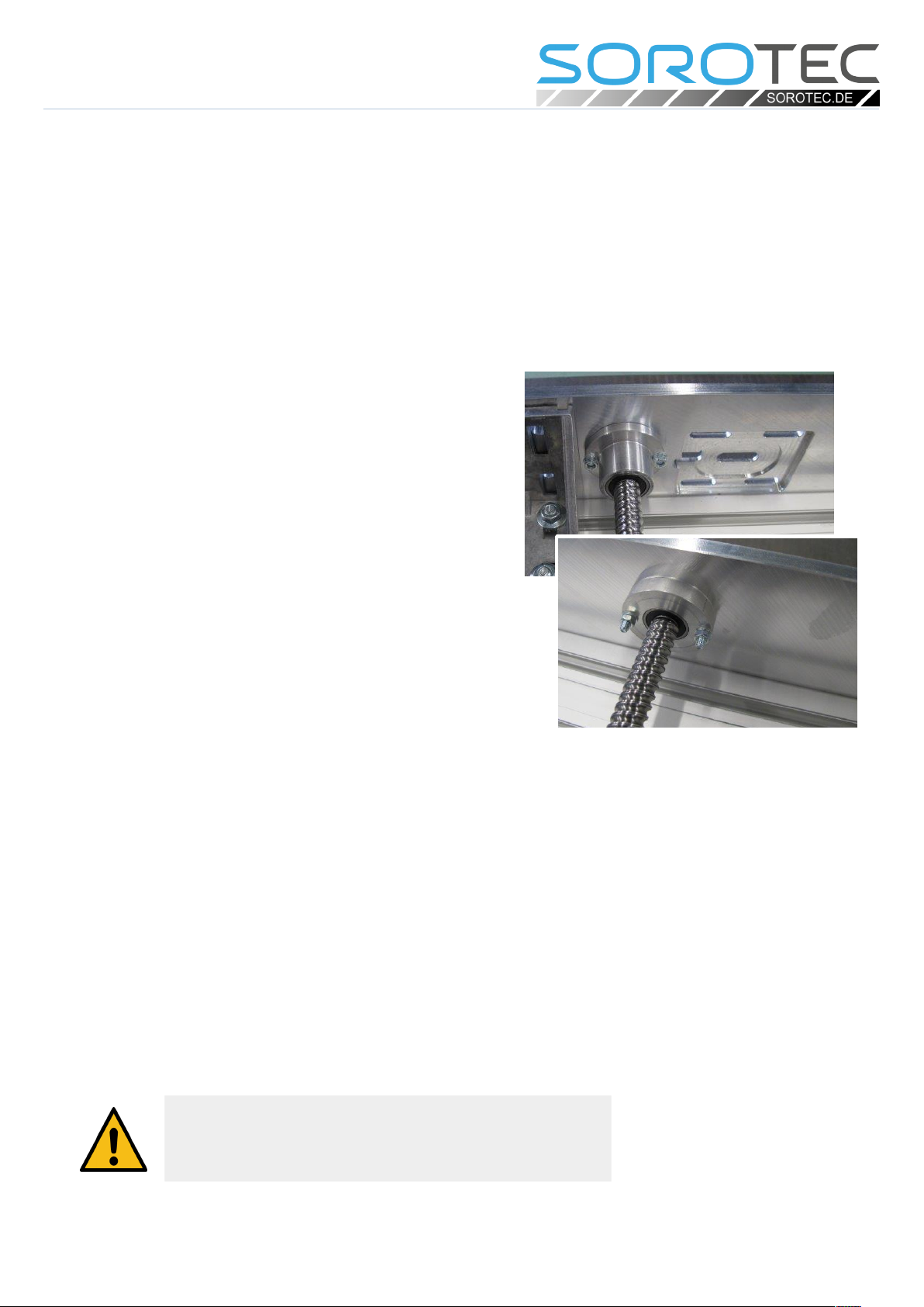
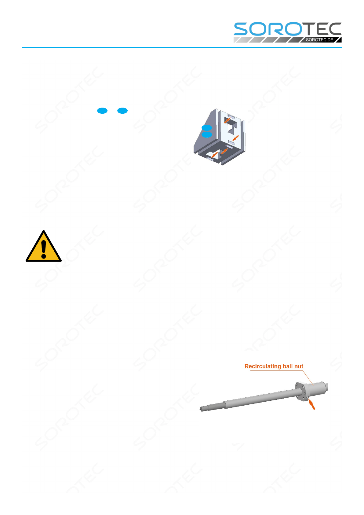
Fixed bearing (above) and floating
bearing in a Sorotec Alu-Line
Attention!
If you have to pull of a bearing that accidentally stuck by
gripping the outer ring, it is likely badly damaged and should
no longer be used.

Page 7/26
Assembly instructions
Basic-Line kit
www.sorotec.de V 2.3.3
Preparatory work
Preparing angles for surface
mounting
When installing an angle 34 or 35 on a component
without fastening grooves, the centering tabs on the
angle must be removed before installation (see Figu-
re 1). This can be done by breaking o with a screw-
driver or ling / sanding.
Fig. 1: Centering tabs on mounting bracket
35
34
Pre-assembly of the ball screws,
spindle nuts and bearing units
Caution!
The pre-assembled recirculating ball nuts must not
be turned o the ball screws!
The ball nuts and ball screwsare sensitive and must
be handled with care!
Install the grease nipple
(all drives):
Equip all ball nuts with 90° angled grease nipples
(see picture 2). Do not fully tighten the grease nipples
to be able to align them later.
Fig 2: Bore and thread for grease nipples
Questo manuale è adatto per i seguenti modelli
3
Indice
Altri manuali Sorotec Utensili elettrici


