9 / 19
F1.14 corresponding setting
AI input setting selection
Units digit: AI1 below the minimum input
setting selection;
0: Corresponding to the minimum input F1.13
1: 0.0%
DI terminal mode selection
1
Units digit:DI1:
0:High-level active; 1: Low-level active;
Tens digit: DI2 (Same as units digit);
Hundreds digit:DI3 (Same as units digit);
Thousands digit:DI4 (Same as units digit);
Ten thousands digit:DI5 (Same as units digit)
Define the input terminal
repeatability
0:Unrepeatable; 1:Repeatable, multiple
DI can use the same input function
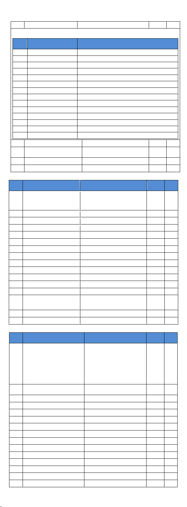
7.4. F2 group Output terminals
Relay output function selection (TA-TC)
Relay output function description:
When the inverter is in running state (the output frequency
can be anything including zero), the output signal is ON.
Fault output (Fault down )
When the drive fails and stops, the output signal is ON.
Frequency level detection FDT1
output
Please refer to the function code F7.23, F7.24's instructions.
Please refer to the description of function code F7.25.
Zero-speed running (No output
when shutdown)
If the inverter is running and the output frequency is 0, signal
is ON. When the drive is shut down, the signal is OFF.
Before motor overload protection, a pre-alarm can be
configured. If the load is more than the pre-alarm threshold
value, this signal is ON. Motor overload parameter settings
refer to function code F8.02~F8.04.
Inverter overload pre-alarm
10s before inverter overload fault occurs (which happens
after 60s at 150% of rated current), this signal is turned ON.
When the count reaches the set value of E0.08, output is ON.
Specifies the count value reaches.
Specifies the count value
reaches
When the count reaches the set value of E0.09, output is ON.
Counting Function Reference E0 group.
When the actual detected length is more than E0.05 set
length, output signal is ON.
After the simple PLC completes one cycle, a pulse with a
width of 250ms is output.
Total running time arrival
If the inverter total running time F6.07 is more than F7.21 set
time, output signal is ON.
When the set frequency exceeds the upper or lower frequen-
cy limit, and output frequency is beyond the upper or lower
frequency limit, output signal is ON.
When the drive is in speed control mode, if the output torque
reaches the torque limit, and the inverter is stall protection
status, the output is ON.
When the inverter main circuit and control circuit power
supply has stabilized, and the drive does not detect any fault
information, the drive is in an operational state, output is ON.
When the operating frequency reaches the upper frequency,
output signal is ON.
Lower frequency arrival (No
output when shutdown)
When the operating frequency reaches the lower frequency,
output signal is ON. At stop, signal is OFF.
Under voltage state output
When the inverter is in an undervoltage condition, output
signal is ON.
Refer to the communication protocol.
Zero-speed operation 2 (also
output when shutdown)
The inverter’s output frequency is 0, output signal is ON.
The signal is also ON when shutdown.
Cumulative power-on time arrival
When the inverter's accumulated power-on time F6.08 is
more than F7.20 set time, output signal is ON.
Frequency level detection FDT2
output
Please refer to the function code F7.26, F7.27's instructions.
Frequency 1 reaches output
Please refer to the function code F7.28, F7.29's instructions.
Frequency 2 reaches output
Please refer to the function code F7.30, F7.31's instructions.
Please refer to the function code F7.36, F7.37's instructions.
Please refer to the function code F7.38, F7.39's instructions.
When the timer function selection (F7.42) is valid, and the
drive run time reaches the time set in F7.43/44, output is ON.
When the value of analog input AI1 is greater than F7.51
(AI1 input upper limit) or less than F7.50 (AI1 input lower
limit), output signal is ON.
When the inverter is off-load state, output signal is ON.
If the inverter runs in reverse, output signal is ON
If the output current is lower than F7.32 for a longer time
than F7.33, output signal is ON.
Module temperature reached
If inverter module heatsink temperature (F6.06) reaches the
set module temperature (F7.40), output signal is ON.
Please refer to the function code F7.34, F7.35's instructions.
Lower limit frequency arrival
(Output also in shutdown)
When the set frequency or operating frequency reaches the
lower limit frequency, output signal is ON. In shutdown
state, the signal is also ON.
When the frequency inverter encounters a failure, and the
fault processing mode is set to continue running, output
signal is ON.
Current running time arrival
When the inverter running time since the last start is longer
than the time set by F7.45, output signal is ON.