SpinCore Technologies ClockMaster CM2-100-PCI Manuale utente
Owner’s Manual for the
ClockMaster™
Models:
CM2-100-PCI
SpinCore Technologies, Inc.
3525 NW 67th Avenue
Gainesville, Florida 32653, USA
Phone: (352)-271-7383
http://www.spincore.com

ClockMaster
8/8/20021
www.spincore.com
Congratulations and THANK YOU for choosing a system from SpinCore
Technologies, Inc. We appreciate your business. At SpinCore we try to fully
support the needs of our customers, so if you ever need assistance please
contact us and we will strive to provide the necessary help.
© 2000-2002 SpinCore Technologies, Inc. All rights reserved. SpinCore
Technologies, Inc. reserves the right to make changes to the product(s) or
information herein without notice. PulseBlasterDDS™, PulseBlaster™,
PulseBlasterPlus!, ClockMaster, SpinCore, and the SpinCore Technologies,
Inc. logo are trademarks of SpinCore Technologies, Inc. All other trademarks
are the property of their respective owners.
SpinCore Technologies, Inc. makes every effort to verify the correct
operation of the equipment. This equipment should NOT, however, be used in
system where the failure of a SpinCore device will cause serious damage to
other equipment or harm to a person.

ClockMaster
8/8/20022
www.spincore.com
Contents
Section I: Introduction
1 Quick Product Overview
2 System Architecture
Section II: Installation
1 Quick Installation Guide
Section III: Physical Description
1 Connector Information
Section IV: Programming Information
1 Using the PM02PC01 DLL
2 Ordered Byte Output Description
Section V: Troubleshooting
Appendix I
Sample C++ program (ExampleApp.cpp)
Appendix II
Available Options
3
4
5
6
7
7
9
11
12

ClockMaster
8/8/20023
www.spincore.com
1. Quick Product Overview
The ClockMasteris a variable frequency digital clock generator
implemented on a single PCI board (1/2 size). The output voltage range of
the digital signal is 0V to 2.5V. It is controlled by a simple PCI
interface. The system runs off of a 100 MHz reference clock and has 31 bits
of frequency data, which provides for a frequency resolution of 47 mHz. Its
valid frequency operating range is from 0 Hz to 70 MHz. When the frequency
selected is zero Hz, the output of the system will remain at ground.
Section I: Introduction
ClockMaster
8/8/20024
www.spincore.com
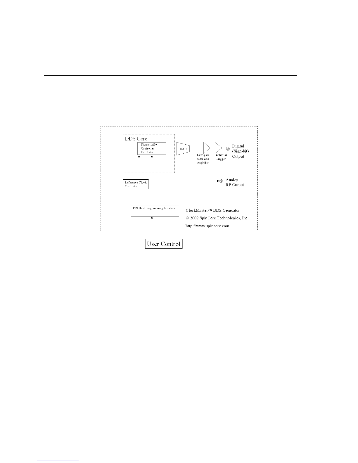
2. System Architecture
Block diagram
Figure 1 presents the general architecture of the ClockMaster.
Fig. 1. ClockMastersystem architecture.
ClockMaster™, Fig. 1, contains a high performance Direct Digital Synthesis
(DDS) system equipped with additional circuitry for frequency control and
output interface. At the core of the ClockMaster™ board is a numerically
controlled oscillator (NCU) with an internal sine lookup table. Digital
output values of the DDS core are converted to sinusoidal waveforms via the
Digital-to-Analog (DAC) converter. The DAC’s output is then filtered,
amplified, and routed to the SMA output connector.
For the purpose of generating low-jitter digital output signals, the
ClockMaster™ is also equipped with a fast Schmidt trigger that extracts the
sign bit information of the generated analog waveforms. The sign bit is the
digital output signal of the system. By generating analog waveforms, low-
pass filtering them, and then extracting the sign bit, the resulting digital
output signals are of improved quality and reduced jitter, compared to the
standard approach where only the Most Significant Bit (MSB) of the DDS’s sine
lookup table is used.
The on-board Schmidt trigger is supplied off of a 2.5 V power supply line
and generates a maximum of 2.5 V voltage swing at the output pin.

ClockMaster
8/8/20025
www.spincore.com
1. Quick Installation Guide
1. Go to http://www.pulseblaster.com/CD/ClockMaster/ and download the zip
file from the correct directory for your operating system.
2. Unzip the files to their own directory.
3. Turn off your computer.
4. Insert the ClockMasterboard into an empty PCI slot.
5. Turn on your computer. The board will automatically be outputting a 25
MHz signal.
6. A dialog box will appear that says “New Hardware Found.” Click “Next”
7. Place a check by the box that says “Specify Location” and uncheck all
others. Click “Next”
8. A window will pop up asking for the driver directory. Click “Browse”
9. Browse to the newly created folder containing the drivers.
10. Click “Open” and then “Next”
11. The next dialog box should say that an appropriate driver was found –
“ClockMaster PM02PC01-100”
12. Click “Next” and “Finish” until installation is complete.
13. Open an MS-DOS window in the directory of the unzipped files.
14. Run install.bat. The following messages should appear:
Creating driver entry… OK.
Starting driver entry… OK.
* If you receive a message that this process fails, please proceed to the
troubleshooting section.
15. Run cmster.exe. You will see:
Usage: cmster <freq (kHz)>
* If you receive a indicating that the board could not be found, please
proceed to the troubleshooting section.
The board is now ready for use. As an example, cmster 1000 will cause the
ClockMasterboard to generate a 1Mhz signal.
Section II: Installation
ClockMaster
8/8/20026
www.spincore.com
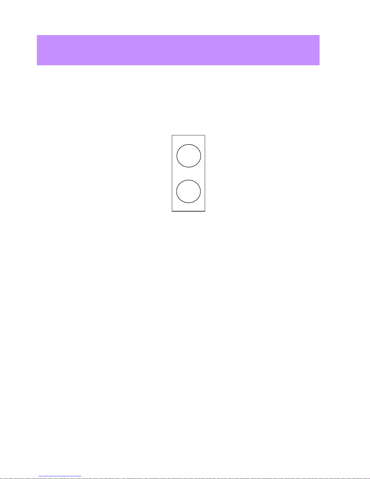
1. Connector Information
Just to the right of the top of the PC bracket, there is a two pin header
named JP800. This is where the output signal of the system is generated. An
illustration of this header and the use of its pins are described below.
Pin 1 – This pin contains the output signal. The output signal is a square
wave with a low voltage of 0V and a high voltage of 2.5V. The frequency of
the signal is set through the PCI interface.
Pin 2 – Ground
On the cable provided by SpinCore Technologies, Inc., one of the two lines
has stranded silver cable exposed. This is the ground pin and should be
connected to pin 2 of the header.
Section III: Physical Description
JP800
1
2

ClockMaster
8/8/20027
www.spincore.com
Programming Notes for ClockMaster
:
1. Using the PM02PC01 DLL
In order to change the output frequency of the ClockMaster, we have
packaged a DLL (pm02pc01.dll) and a library file (pm02pc01.lib) that provide
a function with this capability. Use of this function is demonstrated below.
Provided Functions
int cm_set_freq(double frequency);
This function accepts desired output frequency as its input and returns a
0 if the call was successful.
double frequency – value of desired output frequency (in kHz).
2. Ordered Byte Output Description
All data transfers to the ClockMasterare sent to the base address of the
I/O space defined for the card plus an offset of 0x0C. Data transfers
involve the sending of 8 bytes of data. The data transfer must take place in
the following manner. The top four bits of each output word must start at
0xF and toggle between 0xF and 0x0 for each byte output. The lower four bits
of each output word are the bits of the desired output word, starting with
the most significant 4 bits.
Example Output:
The following is an example of the output sequence to program the
ClockMaster. Explanations are included in brackets in the middle of the
code. Use this method only if you are writing directly to the output port by
using an _outp or similar function and not using the provided functions and
drivers.
First, you must find the new data value to transfer based on the desired
frequency. The formula for finding the desire frequency is
Output Word = Desired Frequency (in MHz)* 2^32 / Clock Frequency (in MHz)
For example, if you wanted an output frequency of 19.6415 MHz on a 50 MHz
system
Output Word = 19.6415 * 2^32 / 50 = 1687192002.88768 ≈1687192003
= 0x649081C3
Section IV: Pro
g
rammin
g
Information

ClockMaster
8/8/20028
www.spincore.com
With this example, the output of the program would be
Output "0xF6" to port base + 0x0C
Output "0x04" to port base + 0x0C
Output “0xF9” to port base + 0x0C
Output “0x00” to port base + 0x0C
Output “0xF8” to port base + 0x0C
Output “0x01” to port base + 0x0C
Output “0xFC” to port base + 0x0C
Output “0x03” to port base + 0x0C

ClockMaster
8/8/20029
www.spincore.com
Note - This troubleshooting guide is only for Microsoft Operating systems.
I. Problem: ‘Failed’ Message Received on Running Install
Solution:
1. Driver may already be installed. Run Uninstall.bat and re-run
Install.bat. If the problem persists, and cmster.exe returns an error,
proceed to step 2.
2. Please be sure you are running the latest ClockMasterdrivers from
www.pulseblaster.com.
II. Problem: ‘No cards found.’ message received upon running cmster.exe or
your own developed application
Solution:
1. Check to make sure that the card is properly inserted into the PCI
slot and reboot your computer.
2. Open Device Manger. Under Multifunction adapters there should be an
entry for ClockMasterPM02PC01. If you see the ClockMastercard,
please proceed to step 3. If there is no entry for the ClockMaster
PM02PC01 device, look for ‘PCI Card’ with an exclamation mark on it.
Select ‘Properties’ for the PCI Card, and reinstall the driver using
SpinCore’s drivers. Reboot your computer.
3. Double click on this device to make sure it is working properly. If
it is not working properly, you should see one of the following
messages:
Error message 1: Device is not present, or is not working properly
Check to make sure that the card is properly inserted into the PCI
slot and reboot your computer. If this does not fix the problem,
try inserting the card into another PCI slot. If neither of these
steps work, please follow the solution to Error message 2.
Error message 2: Windows cannot load the driver for this device
Download another copy of the drivers from www.pulseblaster.com
for your particular operating system. Extract the installation
files from the zip file.
Under the device manager properties for the ClockMaster, click on
the “Reinstall Driver” button and follow the steps listed in the
Quick Installation Guide.
Section V: Troubleshootin
g
Indice
Altri manuali SpinCore Technologies Scheda PCI

SpinCore Technologies
SpinCore Technologies PulseBlaster DDS-III Manuale utente

SpinCore Technologies
SpinCore Technologies RadioProcessor USB Manuale utente

SpinCore Technologies
SpinCore Technologies PulseBlaster PB24-100-PCI Manuale utente

SpinCore Technologies
SpinCore Technologies PulseBlasterESR-PRO SP4B Manuale utente

SpinCore Technologies
SpinCore Technologies PulseBlasterESR-PRO-II Manuale utente

SpinCore Technologies
SpinCore Technologies RadioProcessor-G Manuale utente


