SPX Cooling Technologies MARLEY 07-1126 Manuale utente

/Marley Ultra Low-Noise Fan /
User Manual 07-1126

3
Contents
General Information...................................................................... 4
Installation .................................................................................... 5
Operation.................................................................................... 11
Maintenance
..............................................................................
13
Parts List .................................................................................... 16
Trouble Shooting ........................................................................ 17

4
General Information
Description
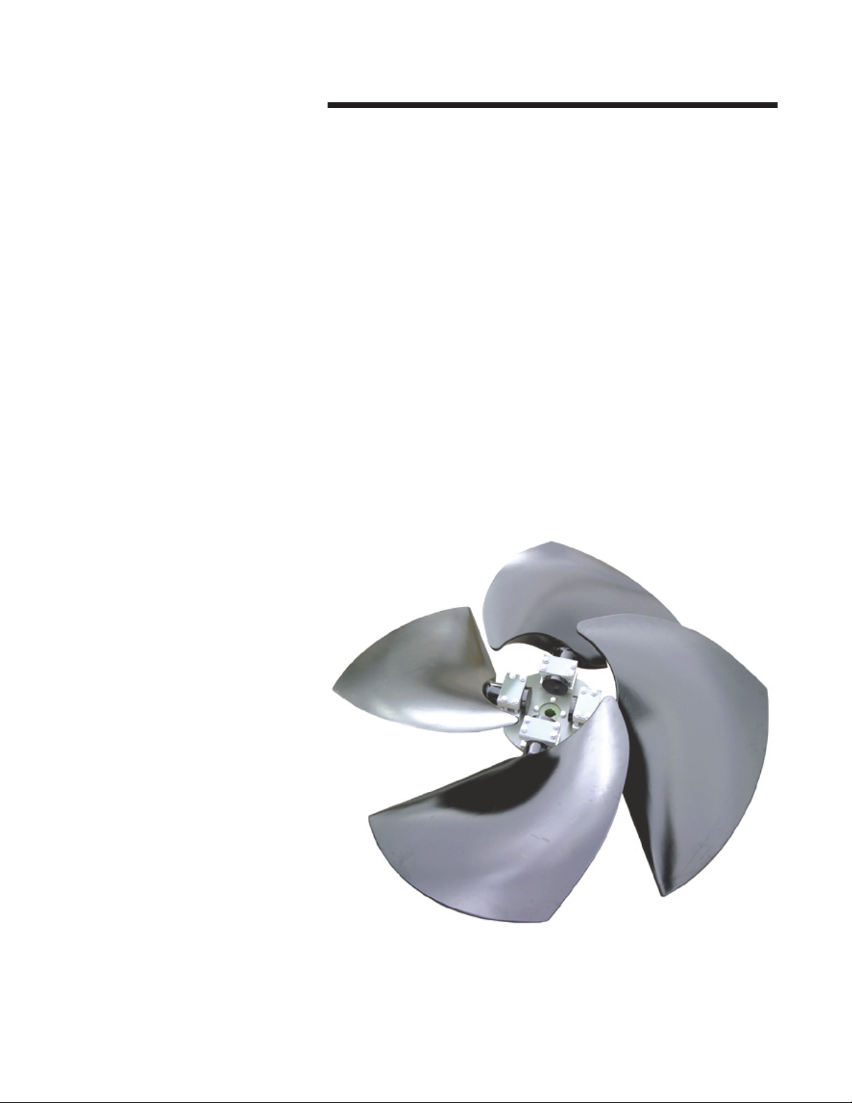
The Marley Ultra Low-Noise series of fans represent the top in the
new generation of super low noise fans—the FRP blades have been
developed to meet the most stringent noise limitations. The fans
permit variable pitch adjustment at standstill and feature a simplified
design. Each blade is fixed to the hub with two bolted aluminum
pillow blocks.
Balancing
When the rotor is dispatched in assembled form, each unit is dy-
namically balanced within a degree of G = 6.3 in accordance with
ISO 1940/1.
When the fan is dispatched disassembled, the hub is dynamically
balanced and the blades are statically balanced so that the reas-
sembled unit correspond to a degree of G = 6.3 in accordance with
ISO 1940/1. In this case, the blades have the same static moment,
so that they can be positioned in any order on the hub; the blades
of the same supply, are interchangeable.
Storage
Upon unloading the fan, inspect it for any damage. If damage oc-
curred, file a claim immediately against the carrier and mark the bill
of loading accordingly.
After the fan delivery, check the full compliance between order and
delivered goods. Shortages or inconformities have to be reported
within two weeks from receipt of shipment at destination.
If not installed immediately, it is recommended to store the fan in
a dry and shaded area, and do not put any heavy materials of any
kind upon the blades. For long-term storage, it is necessary to check
the condition of the corrosion preventive coating on all machined
surfaces.
5
Installation
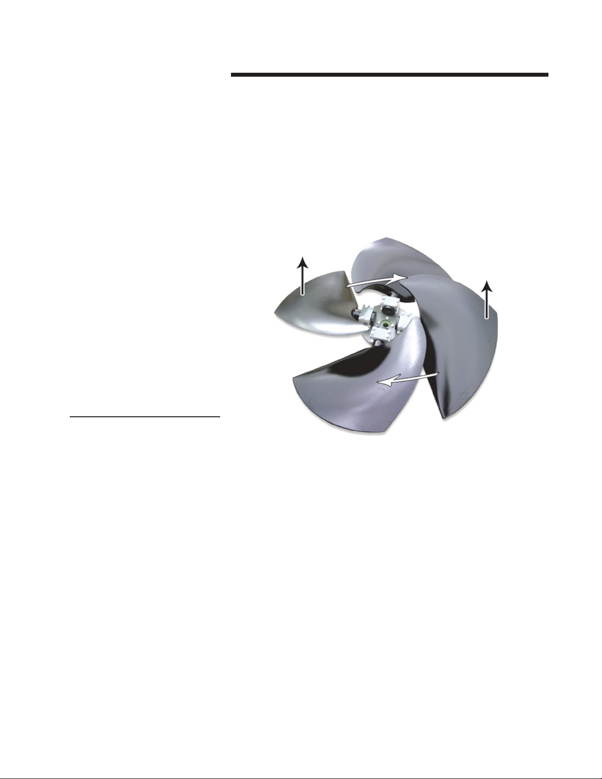
Rotation and Flow Direction
The rotation direction is correct when the airflow moves from the
convex back (suction surface) of the blade, to the concave side
(pressure surface). Figure 1 shows the conventional clockwise di-
rection of rotation and normal direction of airflow as viewed from
the discharge face of the rotor.
Installation Instructions
1––Remove blade pillow block and fasteners 4, 5, 6, 7, 15 from the
hub disk, one set a time (Figure 2).
2––If the hub has not been supplied already assembled to the flange,
install the coupling flange 2on the disk 3, complying with torque
settings, bolt orientation, tightening order, and pins as shown in the
table following Figure 2.
Flow Direction
Flow Direction
Figure 1
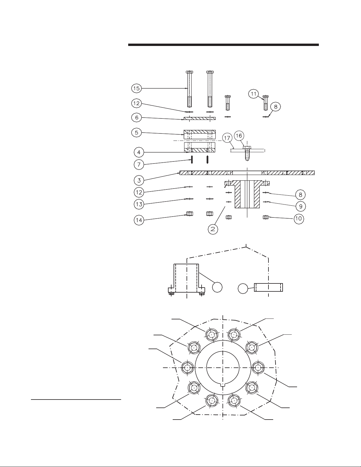
6
Installation
10B10A
1
5
93
7
2
6
104
8
Figure 2

7
Installation
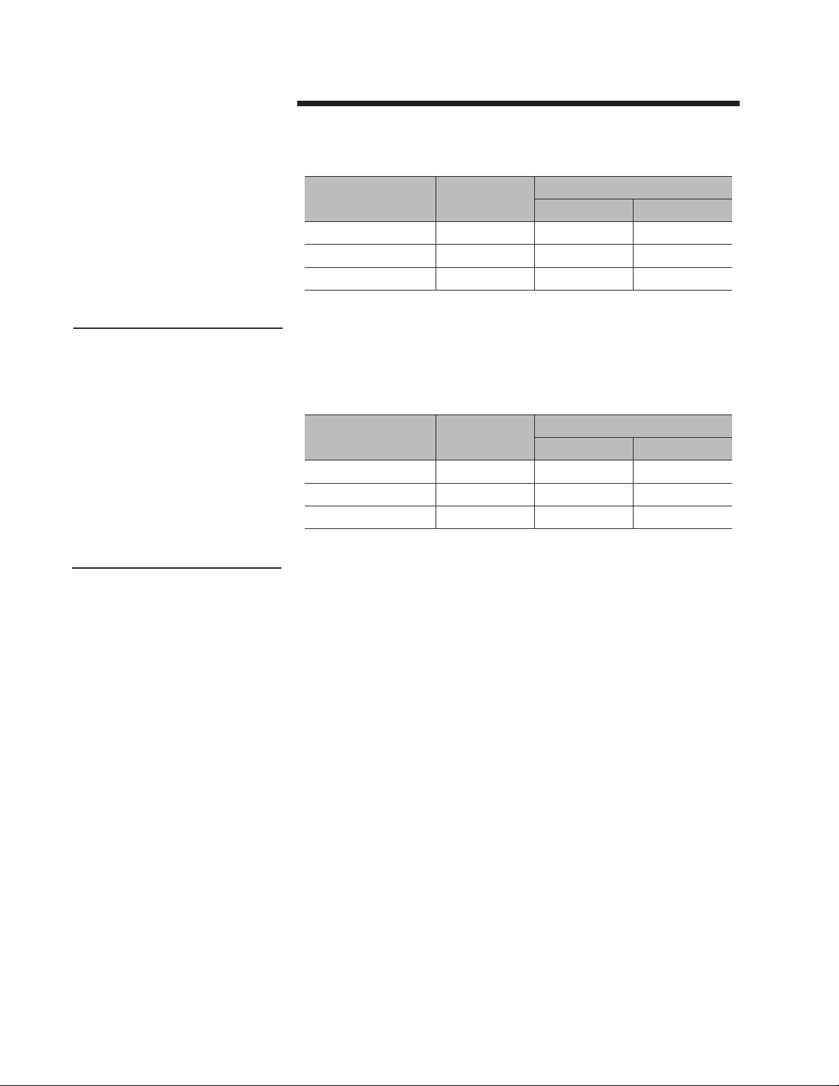
Torque hub assembly bolts 11 according to the following table:
Fan Diameter
inches Flange Type Bolt Type Bolt Torque
N·m ft·lb
84" to 96" Type 115
M16 cl. 8.8 230 169
M16 cl. A4-70 126 93
M16 cl. A4-80 168 124
108" to 168" Type 190
M20 cl. 8.8 447 329
M20 cl. A4-70 246 181
M20 cl. A4-80 328 241
3––Hub into driveshaft installation (Figure 2).
• As for the hub with cylindrical bore, the hub is bored to attach
directly to the drive shaft.
Coat the output drive shaft with a thin layer of silicon grease.
If a space ring 10A is supplied, drive it into the drive shaft until it
comes in contact with the drive shaft shoulder.
Drive the hub with cylindrical bore into the drive shaft until it comes
in contact with the drive shaft shoulder (or space ring shoulder if
supplied).
Never power the drive shaft with special washer 16 and the retain-
ing bolt 17 missing or loose.
• As for the hub with tapered bushing hole, be sure drive shaft,
bushing and hub bore are not greased. Slide the bushing into the
drive shaft to your design position.
Position the hub core over the bushing taper; insert bushing screws
through the bushing flange into the threaded hole in the hub coupling;
torque bushing screws according to the following table:
Bushing Type Screw Torque
N·m ft·lb
Q1 and Q2 40 29
R1 and R2 40 29
Warning

8
Installation
The drive shaft end must remain recessed at least 1⁄32" in the hub
bore to prevent dangerous rotor vertical translation once retaining
bolt 16 has been tightened to the shaft end.
Never power the drive shaft with bushing bolts not torqued or
bushing improperly positioned.
4––Install the blade.
Sandwich the blade shank between the pillow blocks 4and 5, en-
suring both the pins 7are in proper position (Figure 2).
Fit pillow blocks 4and 5, pins 7, pillow block plate 6, blade and
pillow block fasteners 15 on hub disk as shown in previous Figure
3 without tightening bolts.
Rotate fan to check tip clearance is in accordance with the specified
value (tip clearance ratio x/D, where x = the distance from the blade
tip to the fan ring and D = the rotor diameter). The gap between
blade tip and fan ring must be measured along blade axis.
Tighten the pillow block bolts 15, to hold the blade in extended
position, leaving enough clearance to allow blade rotation on its
own axis for pitch setting.
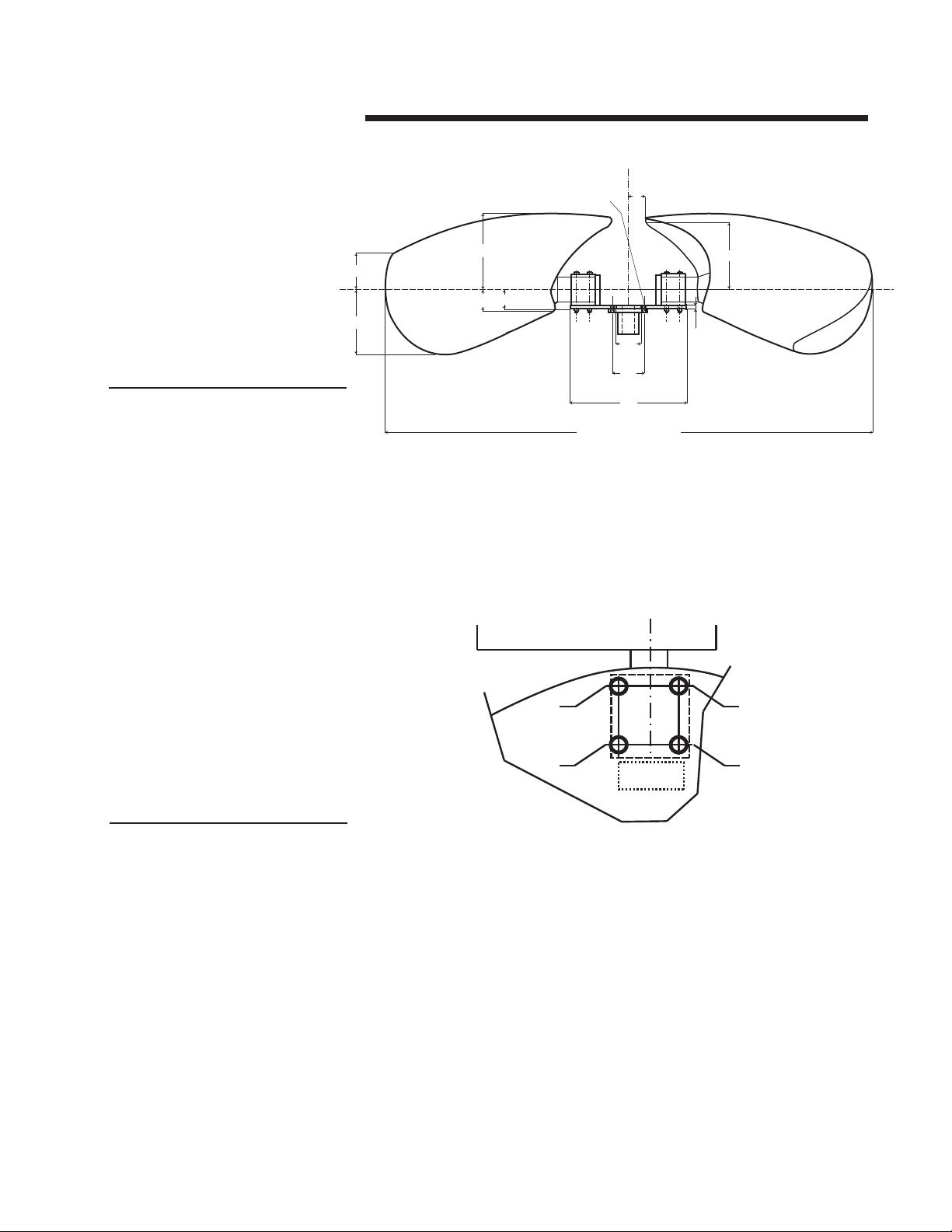
5––Setting blade pitch.
The pitch angle of each blade has to be set at the A° value specified
in the rotor identification plate with a 0.5° maximum tolerance: in
order to set the pitch, the quotes shown in following Figure 3 must
be observed; note these quotes are shown on the fan data sheet, and
are specific for each diameter of the Marley Ultra Low-Noise fan.
Caution
Warning
9
Installation
Rotate the blade on its axis until the required pitch angle is ob-
tained.
Check there is no gap between each blade shaft shoulder and cor-
responding pillow block.
Torque pillow block bolts 15 according to the following tables,
complying with bolt orientation and tightening order as shown in
Figure 4.
6––Repeat for each blade steps described in points 4 and 5. Before
starting the pitch angle setting procedure, turn the fan till the blade
to be set is at the same point in the fan ring where previous pitch
angle was set.
In order to determine the torque setting of standard bolts 15, with
the 8.8 stamping, search in the following table the bolt type set for
the diameter of the fan in object.
Figure 3
Figure 4
U
V
S
T
K
øF
øE
øC
FAN DIAMTER (A)
Z
R
D
G X øH
1
2
3
4
4 Bolt Pillow Block Tightening Order
10
Installation
Fan Diameter
inches Bolt 15 Bolt Torque
N·m ft·lb
84" to 96" M18 282.5 208
108" to 120" M20 400.3 294
132" to 144" M24 679.8 500
The screw class information is shown in the fan documenta-
tion part list.
Stainless steel bolts 15 with the A4-80 stamping:
Fan Diameter
inches Bolt 15 Bolt Torque
N·m ft·lb
84" to 96" M18 175.6 129
108" to 120" M20 246.2 181
132" to 144" M24 425.7 313
In the case of a structure equipped with multiple fans, before
setting the pitch angle to all the fans, set the pitch on one fan
only and follow the instructions for operation starting on page
11.
Note
Note
Questo manuale è adatto per i seguenti modelli
1
Indice
Altri manuali SPX Cooling Technologies Fan


