Standby LB200 Manuale utente
standbygroup.se
(SE)+46 520 494440 • email: info-se@standbygroup.com
Page 1
ENGLISH
Operating Manual
Valid for:
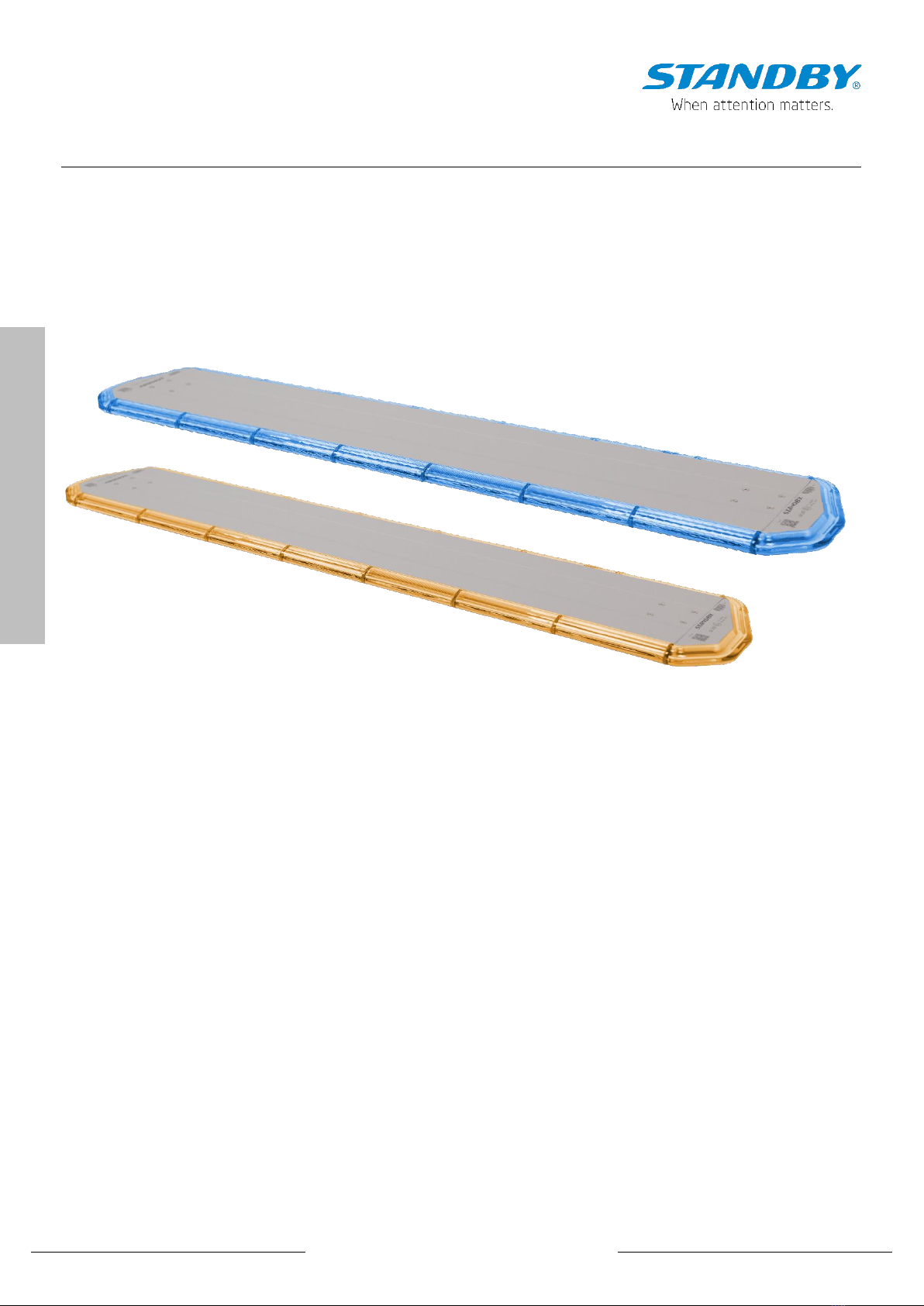
506584xxxxx –LB200 469 –1847 mm
Document: 50658400001980 (0)
Language: English
Issue date: 11/2023
standbygroup.se
(SE)+46 520 494440 • email: info-se@standbygroup.com
Page 2
ENGLISH
Liability notice
LIMITATIONS OF LIABILITY
The products have been developed in accordance with the applicable standards and regulations. The information collected in the technical documentation takes into
account the state of the art as well as the knowledge and experience acquired over many years.
Standby is not liable for damage and consequences due to:
•Failure to comply with the information in the product documentation
•Non-compliant use of the product
•Assembly and application of products manufactured by unskilled workers
•Unauthorized changes made by the user or the operator himself
•Technical changes not submitted to or approved by Standby
•Use of spare parts that are not approved by Standby
BUILDER'S RESPONSIBILITIES
The body builder is fully responsible for assembling the equipment on a vehicle.
The body builder must define the means and materials required to assemble the equipment in order to deliver the vehicle equipped according to the regulations.
Standby is not responsible for errors resulting from a wrong definition of the type of mounting system, the reinforcements, the holes in the roof panel, the condition and
quality of the mounting system, the use of anchoring points by the vehicle manufacturer and the definition of the power supply and protection of the system according to
the energy source of the vehicle.
USER AND OPERATOR RESPONSIBILITIES
Standby products are professional devices that may only be used for this purpose. Their implementation is subject to legal obligations with regard to workplace safety to
which the operator must submit. The same applies to safety and accident prevention regulations as well as environmental protection regulations. Use of these devices on
the road is subject to traffic laws and regulations.
Obligations of the operator:
•Find out about the applicable occupational safety regulations
•Carrying out a risk analysis of specific working conditions at the intervention site
•Adapting user training to regulations, standards and conditions of use
•When using the device, periodically review the adequacy of the implementation rules against the applicable safety rules and standards.
•To ensure that the operator has read and understood the device's user manual.
•Ensure users are regularly trained in their use and informed of the dangers associated with implementing the equipment.
•To provide the personnel with protective equipment adapted to the operation and to ensure that it is used.
It is the responsibility of the operator:
•Ensuring the curative and preventive maintenance of devices
•Ensure that safety devices are checked regularly
USAGE
Intended Use
The special signal system is intended for use on vehicles with an on-board voltage of 12 V or 24 V.
When using it on public roads, the statutory provisions must be observed.
Improper use
Any use beyond this is considered improper.
The manufacturer is not liable for damage resulting from improper use; the operator bears the risk.
Cleaning the coloured domes
A mild, alcohol-free cleaning agent (washing-up liquid, car shampoo) should be used for cleaning, as otherwise cracks and damage can occur.
General cleaning
If the lightbar is cleaned intensively (e.g. with a high-pressure cleaner or in long car washes), the inside of the lightbar can condense up. This type of cleaning should be
avoided.
NOTE ON RADIO ANTENNA INSTALLATION
It is recommended to mount the BOS radio antenna at a distance of ≥ 1 m from the light bar in order to avoid radio interference. The absolute minimum distance of 0.5 m
should never be undercut.
CUSTOMER SERVICE
The STANDBY CUSTOMER SERVICE is available for technical information:
•Website: standbygroup.se
•Email: support-se@standbygroup.com
•Phone: +46 520 49 44 40
In the interests of continuous improvement, our employees are available to answer any questions you may have about the installation and use of our products.
standbygroup.se
(SE)+46 520 494440 • email: info-se@standbygroup.com
ENGLISH
Page 3
Safety Instructions
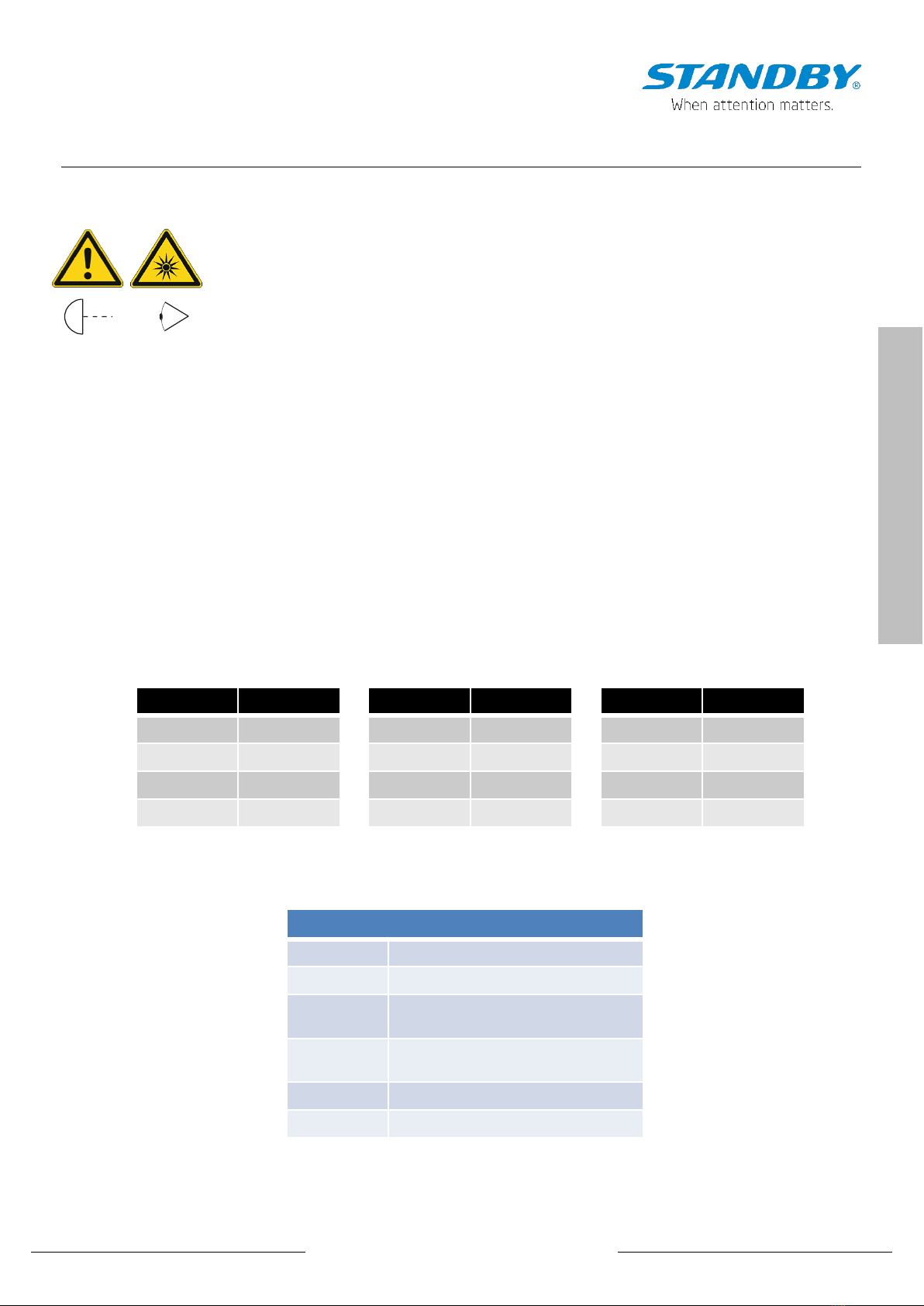
WARNING ABOUT OPTICAL RADIATION
All optical components are classified as low risk in accordance with DIN EN 62471.
Only look into the light beam of the components for a short time (max. 4 minutes) with the paint cap on!
Minimum distance from light source to eye 0.2 m.
Colour code in the connection diagram
Abbreviations with 4 letters are two-colour lines; e.g. WHYE = white/yellow (white cable with yellow stripe)
0,2 m
abbreviation colour abbreviation colour abbreviation colour
RD red WH white VT violet
BK black YE yellow OG orange
BN brown GY grey PK pink
GN green BU blue
Common abbreviations used in this document
PN Part Number
+BAT Operating Voltage
+BAT Battery plus
GND Battery minus
night switch Night switch
sync Synchronisation
standbygroup.se
(SE)+46 520 494440 • email: info-se@standbygroup.com
Page 4
ENGLISH
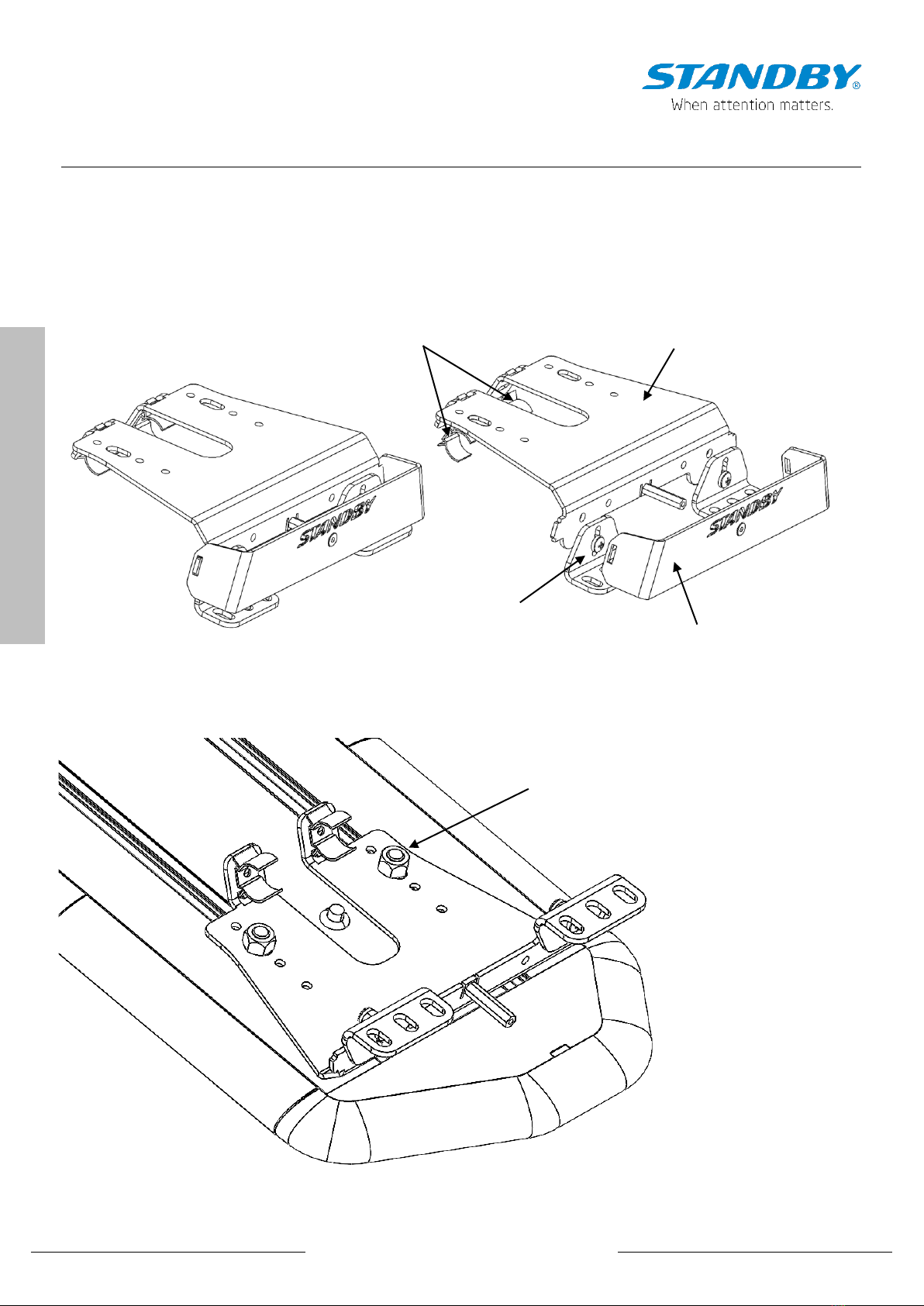
Mounting the light bar
The brackets described here are NOT included in the scope of delivery but are recommended!
Part number: 50658400030
Components of the mounting bracket:
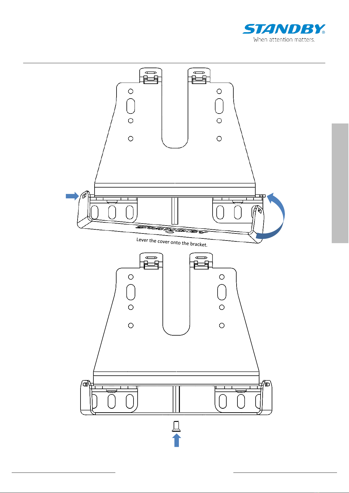
Assembly:
Cover (can be mounted optionally)
Compensation angle
Bracket
Retaining clips for connectors
Insert the M8 hexagon screws into the
grooves provided in the base plate and
tighten the nuts so that the bracket can still
be moved for adjustment.
standbygroup.se
(SE)+46 520 494440 • email: info-se@standbygroup.com
ENGLISH
Page 5
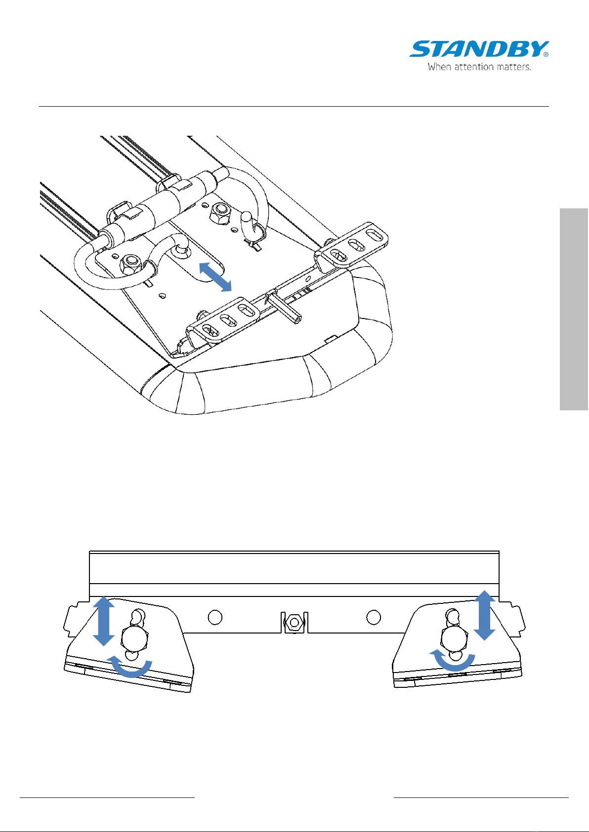
Mounting the light bar
Align the LB200 on the vehicle roof by moving the brackets and
tighten the M8 nuts with 6 Nm.
Insert the plug connector into the retaining clips provided and
guide the cable with the cable ties provided.
Adjusting the height and aligning the brackets using the compensation angles.
The support surface of the bracket must be parallel to the road surface.
The universal holder can be adapted to the
respective roof geometry using the compensation
angles. Tighten the fastening screws with 5-6Nm.

standbygroup.se
(SE)+46 520 494440 • email: info-se@standbygroup.com
Page 6
ENGLISH
Mounting the light bar
In the case of heavily curved vehicles in the side area, the
compensation angles can be bent accordingly and adjusted
slightly if necessary.
Connection points to the
vehicle roof.
Connection points to the roof rails. At least four connection
points should be used per bracket.
Liquid screw locking must be used for all screw connections where no
nut with a clamping part is used.
standbygroup.se
(SE)+46 520 494440 • email: info-se@standbygroup.com
ENGLISH
Page 7
Mounting the light bar
Tighten the screw (torque 2-3Nm, use liquid screw locking agent).
standbygroup.se
(SE)+46 520 494440 • email: info-se@standbygroup.com
Page 8
ENGLISH
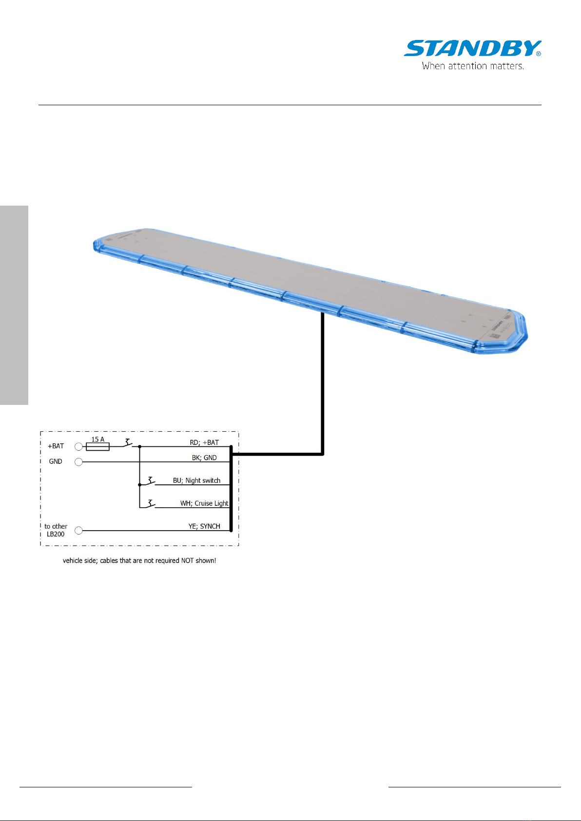
Electrical connection
standbygroup.se
(SE)+46 520 494440 • email: info-se@standbygroup.com
ENGLISH
Page 9
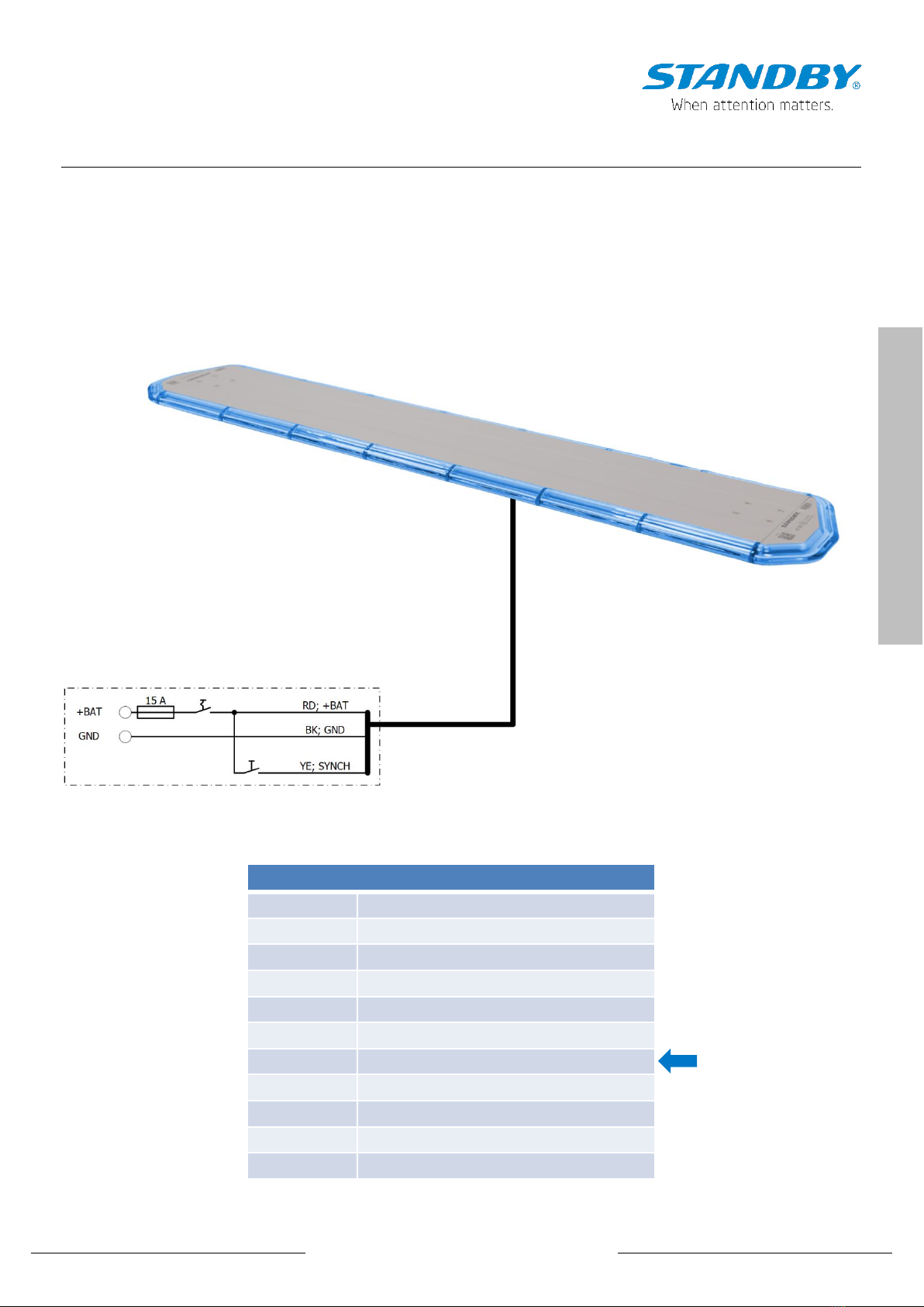
Flash pattern setting
To change the flash pattern of the LB200, the light bar is first connected to the power supply.
Now the flash pattern can be set by pressing the yellow line (synch) against +UB for < 1s. The flash pattern changes according to the
table below.
A button > 3s resets the light bar to the factory setting (triple flash alternating).
Flash pattern
No Flash pattern
1 Single flash synchronous
2 Single flash alternating
3 Double flash synchronous
4 Double flash alternating
5 Tripple flash synchronous
6 Tripple flash alternating
7 Quadruple flash synchronous
8 Quadruple flash alternating
9 ICAO
10 Rotating
Factory default
standbygroup.se
(SE)+46 520 494440 • email: info-se@standbygroup.com
Page 10
ENGLISH
TECHNICAL DATA
Operating Voltage 12/24 VDC (10 … 30 VDC)
Current Consumption 3 –10 A, depending to lightbar length
LED-Colour blue, amber
Dome Colour clear
Flash pattern Single-, Double-, Tripple-, Quadruple flash, alternating or synchronous, ICAO, Rotating
Mounting fix mount
Protection Class IP67
Weight approx. 7 kg/m
Ambient Temperature -40°C - +65°C
Connection Cable 6 m
Available Lengths
blue: 300, 1067, 1220, 1373, 1527 mm
amber: 300, 454, 607, 914, 1067, 1220, 1373, 1527, 1833 mm
Height 25,5 mm (without bracket)
Depth 220 mm
Approvals ECE R10, CISPR 25 Class 3
ECE R65 Class 2 (Single- and Tripple flash, synchronous and alternating)
Technical Data
Indice
Altri manuali Standby Accessori per automobili

Standby
Standby P1 PANEL Manuale utente

Standby
Standby L52 Manuale utente

Standby
Standby Vega Manuale utente

Standby
Standby L52 2C Manuale utente

Standby
Standby L88 Manuale utente

Standby
Standby L52 Manuale utente

Standby
Standby W3 Manuale utente

Standby
Standby W3 Manuale utente

Standby
Standby L54 Manuale utente

Standby
Standby P4 Manuale utente


