
Star Lake SCH-406 Manuale utente

User’s Manual
Revision Date: June.11.2021
SCH-406
IEC-61850-3, IEEE-1613 1U Computer

SCH-406 User’s Manual
Revision Date: June.11.2021
1
Safety Information
Electrical safety
To prevent electrical shock hazard, disconnect the power cable from the electrical outlet before
relocating the system.
When adding or removing devices to or from the system, ensure that the power cables for the devices
are unplugged before the signal cables are connected. If possible, disconnect all power cables from
the existing system before you add a device.
Before connecting or removing signal cables from the motherboard, ensure that all power cables are
unplugged.
Seek professional assistance before using an adapter or extension cord. These devices could interrupt
the grounding circuit.
Make sure that your power supply is set to the correct voltage in your area.
If you are not sure about the voltage of the electrical outlet you are using, contact your local power
company.
If the power supply is broken, do not try to fix it by yourself. Contact a qualified service technician or
your local distributor.
Operation safety
Before installing the motherboard and adding devices on it, carefully read all the manuals that came
with the package.
Before using the product, make sure all cables are correctly connected and the power cables are not
damaged. If you detect any damage, contact your dealer immediately.
To avoid short circuits, keep paper clips, screws, and staples away from connectors, slots, sockets and
circuitry.
Avoid dust, humidity, and temperature extremes. Do not place the product in any area where it may
become wet.
Place the product on a stable surface.
If you encounter any technical problems with the product, contact your local distributor
Statement
All rights reserved. No part of this publication may be reproduced in any form or by any means,
without prior written permission from the publisher.
All trademarks are the properties of the respective owners.
All product specifications are subject to change without prior notice
SCH-406 User’s Manual
Revision Date: June.11.2021
2
Revision History
Revision
Date (yyyy/mm/dd)
Changes
V1.0
2021/06/11
First release
Packing List
Item
Description
Q’ty
1
SCH-406 IEC-61850-3, IEEE-1613 1U Computer
1
2
Driver CD
1
Ordering information
2U 19” Power Automation Fanless Server Computer with Intel. 10th Gen. Core i7 Processor,
2 × RJ45 GbE, 2 x 10GbE, 100V~240V AC-in, 2 x 200W AC/DC Redundant Power Supply, Operating
Temperature -20~+60°C
Optional Ordering Information
INTEL X710 Dual 10GbE SFP+ LAN card

SCH-406 User’s Manual
Revision Date: June.11.2021
3
RoHS Compliance
Perfectron RoHS Environmental Policy and Status Update
Perfectron is a global citizen for building the digital infrastructure. We are
committed to providing green products and services, which are compliant with
European Union RoHS (Restriction on Use of Hazardous Substance in Electronic Equipment)
directive 2011/65/EU, to be your trusted green partner and to protect our environment.
In order to meet the RoHS compliant directives, Perfectron has established an engineering and
manufacturing task force to implement the introduction of green products. The task force will
ensure that we follow the standard Perfectron development procedure and that all the new RoHS
components and new manufacturing processes maintain the highest industry quality levels for
which Perfectron are renowned.
The model selection criteria will be based on market demand. Vendors and suppliers will ensure
that all designed components will be RoHS compliant

SCH-406 User’s Manual
Revision Date: June.11.2021
4
Chapter 1 : Production Introduction...........................................................................................5
1.1 Specification.............................................................................................................................5
1.2 Front Panel I/O Placement.......................................................................................................7
1.3 Rear Panel I/O Placement ........................................................................................................8
1.4 Mechanical Dimensions ...........................................................................................................9
Chapter 2 : Rear I/O Ports............................................................................................................10
2.1 LAN/IPMI port ........................................................................................................................10
2.2 VGA/DVI-D port......................................................................................................................10
2.3 USB3.2 port ............................................................................................................................10
Chapter 3 : System Setup .............................................................................................................11
3.1 Removing the Top Cover from the Chassis ............................................................................11
3.2 Installing PCIe Card.................................................................................................................11
3.3 Install the screws on the upper cover....................................................................................12
3.4 2.5” Easy Swap SSD installation .............................................................................................12
Chapter 4: AMI BIOS UTILITY ......................................................................................................13
4.1 Starting...................................................................................................................................13
4.2 Navigation Keys ......................................................................................................................14
4.3 Main Setup .............................................................................................................................14
4.4 Advanced Setup Configuations ..............................................................................................17
4.5 Event Logs ..............................................................................................................................51
4.6 IPMI ........................................................................................................................................53
4.7 Security...................................................................................................................................56
4.8 Boot........................................................................................................................................63
4.9 Save & Exit..............................................................................................................................66
Chapter 5: Appendix A BIOS Codes ...........................................................................................68
5.1 BIOS Error POST (Beep) Codes ...............................................................................................68
5.2 Additional BIOS POST Codes ..................................................................................................69
Chapter 6 : Appendix B Software...............................................................................................70
6.1 Microsoft Windows OS Installation........................................................................................70
6.2 Driver Installation...................................................................................................................72
6.3 SuperDoctor® 5 ......................................................................................................................73
6.4 IPMI ........................................................................................................................................74
Chapter 7: Appendix C Standardized Warning Statements................................................75
Chapter 8:Appendix D UEFI BIOS Recovery ............................................................................78
8.1 Overview ................................................................................................................................78
8.2 Recovering the UEFI BIOS Image............................................................................................78

SCH-406 User’s Manual
Revision Date: June.11.2021
5
8.3 Recovering the BIOS Block with a USB Device .......................................................................78
Chapter 1 : Production Introduction
1.1 Specification
System
CPU
10th Generation Intel® Core™ i9/i7/i5 Processors
Intel® Core™ i9-10900TE(20M Cache, up to 4.60 GHz)
Intel® Core™ i7-10700TE(16M Cache, up to 4.50 GHz)
Intel® Core™ i5-10500TE(12M Cache, up to 3.70 GHz)
Memory type
4 x DDR4 up to 128GB
Expansion Slot
1 PCI-E 3.0 x16
2 PCI-E 3.0 x4
Storage Device
2 x 2.5” Easy swap HDD/SSD Tray
Rear I/O
Power Button
1 with backlight
Indicator
1 HDD backlight
USB
2 x USB 2.0
Front I/O
Power Input
100V~240V AC-IN
LAN
2 x RJ45 GbE LAN ; 2 x RJ45 10GbE LAN ; 1 x IPMI
USB
4 x USB 3.0
DisplayPort
2 x DP
DVI
1 x DVI-D
VGA
1
Optional
Dual 10GbE+ Module
INTEL X710 Dual 10GbE SFP+
Power
Power Input
100V~240V AC-IN, 2 x 200W AC/DC Redundant Power Supply
OS support list
Windows
Windows 10 x64
SCH-406 User’s Manual
Revision Date: June.11.2021
6
Linux
Ubuntu, Red Hat
Mechanical and Evvironmental
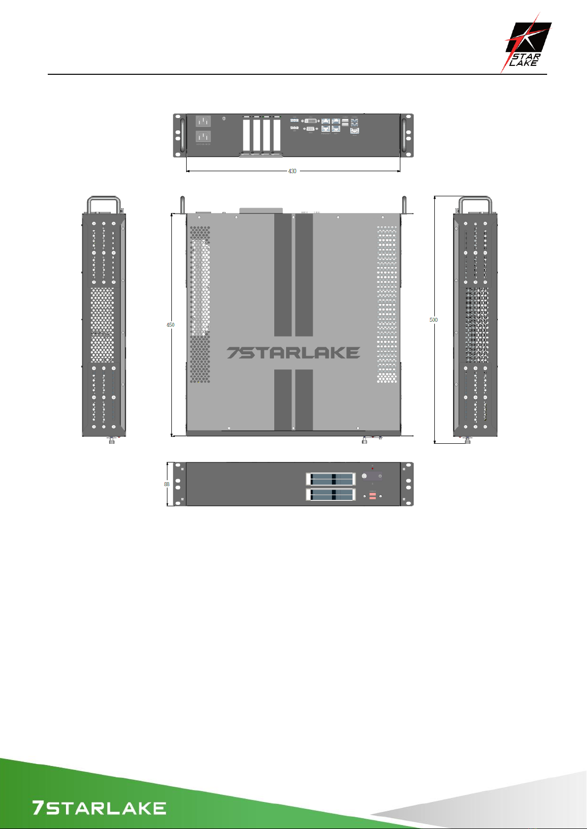
Dimension
430 x 396 x 88 mm ( W x D x H )
Operating Temp.
-20 to 60°C
Storage Temp.
-40°C to 85°C
Relative Humidity
5% to 95%, non-condensing
Certification
CE, FCC, MIL-STD 810G Compliance
System Design
Fanless
Mounting
2U Rackmount
MIL-STD-810G
Test
Method 507.5, Procedure II (Temperature & Humidity)
Method 516.6 Shock-Procedure V Non-Operating (Mechanical Shock)
Method 516.6 Shock-Procedure I Operating (Mechanical Shock)
Method 514.6 Vibration Category 24/Non-Operating (Category 20 & 24,
Vibration)
Method 514.6 Vibration Category 20/Operating (Category 20 & 24, Vibration)
Method 501.5, Procedure I (Storage/High Temperature)
Method 501.5, Procedure II (Operation/High Temperature)
Method 502.5, Procedure I (Storage/Low Temperature)
Method 502.5, Procedure II (Operation/Low Temperature)
Method 503.5, Procedure I (Temperature shock)
EMC
CE, FCC compliant
Green Product
RoHS, WEEE compliance
SCH-406 User’s Manual
Revision Date: June.11.2021
7
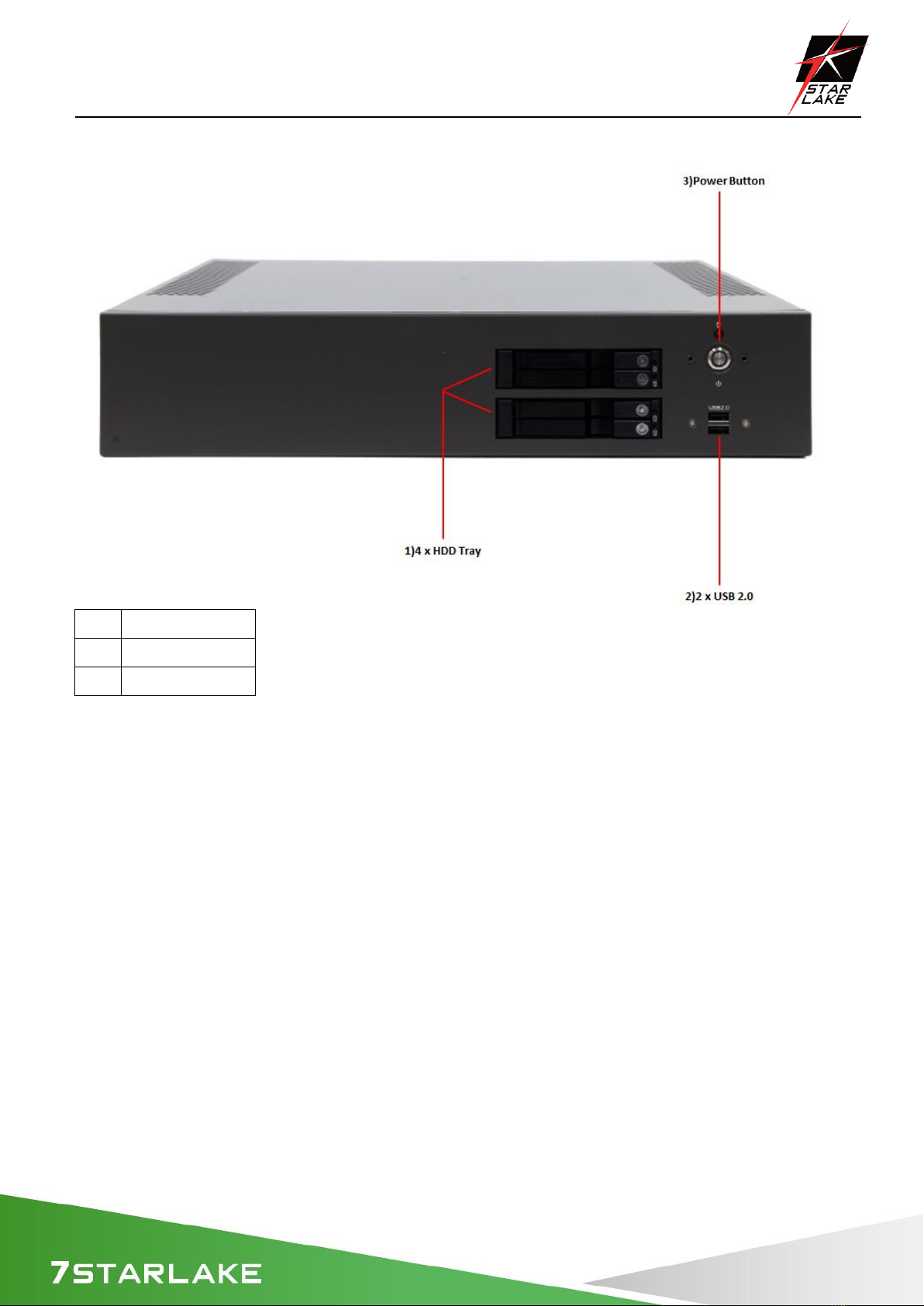
1.2 Front Panel I/O Placement
1)
4 x HDD Tray
2)
2 x USB2.0
3)
Power Button
SCH-406 User’s Manual
Revision Date: June.11.2021
8
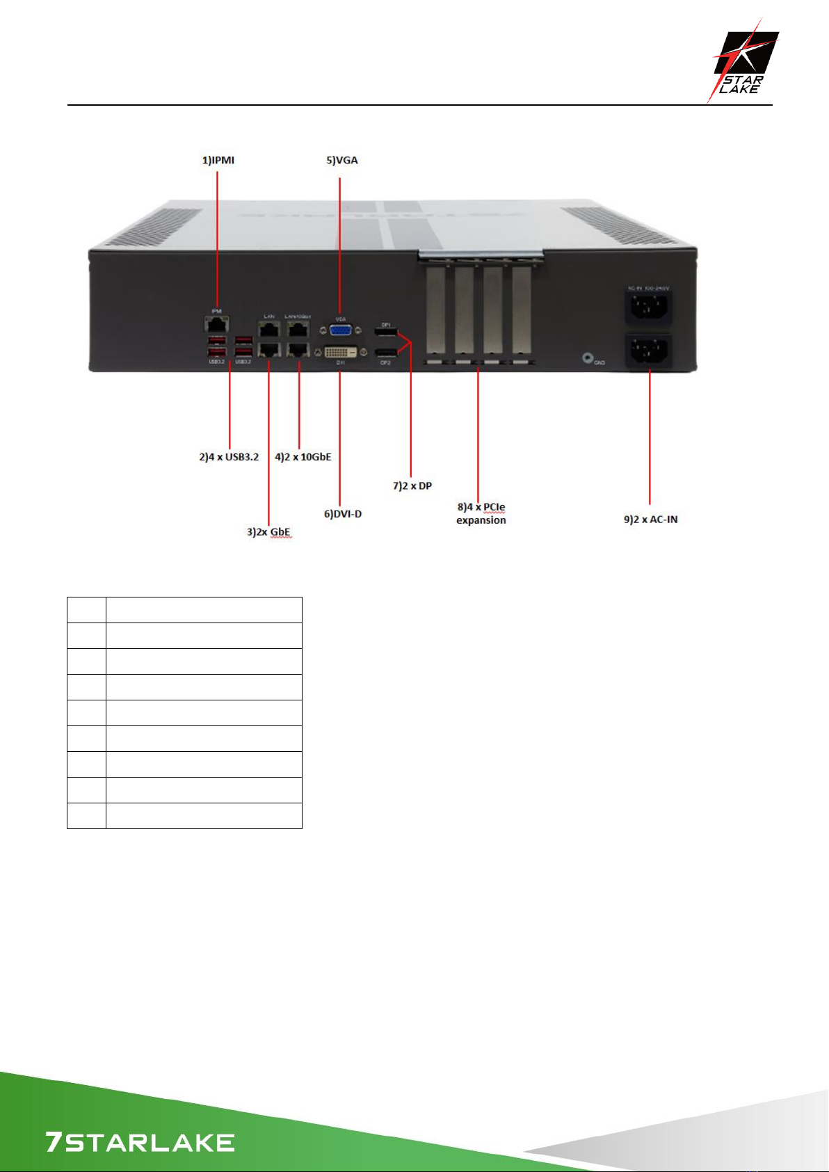
1.3 Rear Panel I/O Placement
1)
IPMI
2)
4 x USB3.2
3)
2 x GbE
4)
2 x 10GbE
5)
VGA
6)
DVI-D
7)
2 x DP
8)
4 x PCIe expansion
9)
2 x AC-IN
SCH-406 User’s Manual
Revision Date: June.11.2021
9
1.4 Mechanical Dimensions
Altri manuali per SCH-406
1
Questo manuale è adatto per i seguenti modelli
2
Indice
Altri manuali Star Lake Scrivania

Star Lake
Star Lake SR10B Manuale utente

Star Lake
Star Lake THOR200-D15EG Manuale utente

Star Lake
Star Lake SR10-SCH Manuale utente

Star Lake
Star Lake ROC286BB Manuale utente

Star Lake
Star Lake SR700 Manuale utente

Star Lake
Star Lake AV710 Manuale utente

Star Lake
Star Lake SCH-406 Manuale utente

Star Lake
Star Lake CPT330B Manuale utente


