
Streckfuss C044 Manuale utente

ISIStreckfuss USA Inc.
C044
Tel: 972-790-1614 - Fax: 972-881-9
J
99
OPERATING MANUAL
Serial Number _ Streckfuss USA. Inc
1401 Capital Ave.
#
B
Plano, TX 75074

TABLE OF CONTENTS
I. GENERAL DESCRIPTION 1
II. SETTING UP THE MACHINE 1
III. ADJUSTMENTS 2-4
IV. OPERATION
5
V. PREVENTIVE MAINTENANCE 5
VII. RECOMMENDED SPARE PARTS 5
VIII. PNEUMATIC DIAGRAM
6
C044

Page 1
C044
I. GENERAL DESCRIPTION:
The Streckfuss model C044 is designed to cut and form the leads of loose axial components for
vertical mounting. A variety of form shapes are available through the use of interchangeable die
sets. Set up adjustments are simple to make and secured to provide accurate forming on every
component. Components are hand fed into the tooling with the body positioned between the
left die and the bending mandrel. Once in position the foot pedal is depressed and the right lead is
clamped securely against the bending mandrel to reduce stress. The die sets are then advanced
cutting and forming the leads in one motion. Depending on the form shape any dimples required
such as stand offs are put in the leads at this point. After the leads have been cut and formed the
die sets retract and the bending jaws advance to bend the leads to the 180
0
configuration. The
bending jaws and clamping die then retract and the finished component is ejected.
II. SETTING UP THE MACHINE:
1. Place the C044 on a suitable work surface. The surface selected should be sturdy enough
to support the weight of the machine.
2. Connect the three air hoses provided from the foot pedal to the machine as shown in
figure 1.
C044
@])
©
00
©
Goo
AIR SUPPLY RATED@60-90PSI
FOOT PEDAL
Figure 1
Page 2
C044
III. ADJUSTMENTS:
A. Form Placement or Cut Length
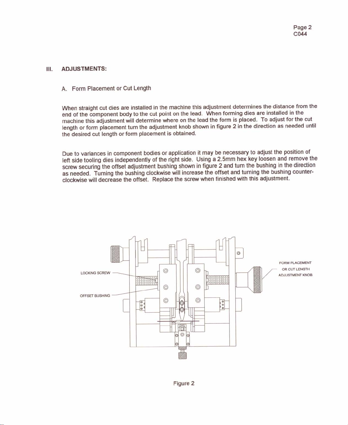
When straight cut dies are installed in the machine this adjustment determines the distance from the
end of the component body to the cut point on the lead. When forming dies are installed in the
machine this adjustment will determine where on the lead the form is placed. To adjust for the cut
length or form placement turn the adjustment knob shown in figure 2 in the direction as needed until
the desired cut length or form placement is obtained.
Due to variances in component bodies or application it may be necessary to adjust the position of
left side tooling dies independently of the right side. Using a 2.5mm hex key loosen and remove the
screw securing the offset adjustment bushing shown in figure 2 and turn the bushing in the direction
as needed. Turning the bushing clockwise will increase the offset and turning the bushing counter-
clockwise will decrease the offset. Replace the screw when finished with this adjustment.
LOCKING SCREW
OFFSET BUSHING
Figure 2
FORM PLACEMENT
OR CUT LENGTH
ADJUSTMENT KNOB
Page 3
C044
III. ADJUSTMENTS: (con't)
B. Component Positioning
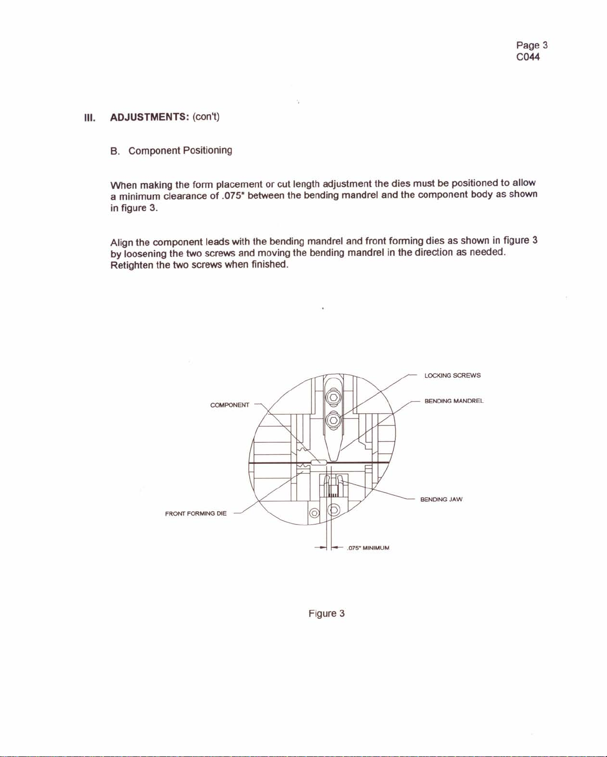
When making the fonn placement or cut length adjustment the dies must be positioned to allow
a minimum clearance of .075 between the bending mandrel and the component body as shown
in figure 3.
Align the component leads with the bending mandrel and front fonning dies as shown in figure 3
by loosening the two screws and moving the bending mandrel in the direction as needed.
Retighten the two screws when finished.
FRONT FORMING DIE
LOCKING SCREWS
BENDING MANDREL
BENDING JAW
Figure 3

Page 4
C044
III. ADJUSTMENTS: (con't)
C. Form Exaggeration And Lead Span
The exaggeration of the form can be adjusted by loosening the screw and turning the eccentric
shown in figure 4 in the direction as needed. Increasing or decreasing the form exaggeration
allows the lead to be custom fit to the hole.
The lead span or center to center distance can be varied from .100 to .200 by adjusting bending
jaws. Loosen the locking nut and turn the adjustment knob shown in figure 4 in the direction as
needed. Retighten the locking nut when finished.
Note: The minimum lead span adjustment is dependent on the width of the bending mandrel.
Changing this adjusment may also require readjusting the offset bushing adjusment.
LOCKING NUT
ADJUSTMENT KNOB
Figure 4
Page 5
C044
IV. OPERATION:
After making the adjustments the C044 is ready to operate. Position a component in the tooling
as described in section III-B. Depress and hold the foot pedal until the component leads have
been cut, formed and bent into the 180
0
configuration. Release the foot pedal and the
component will drop into the tray below the tooling.
V. PREVENTIVE MAINTENANCE:
Daily
Weekly -
Monthly -
Remove all scrap leads and dust particles from the machine with a brush.
Remove the tooling dies, clean thoroughly and relubricate using a light amount of
10w oil. Check for wear.
Lubricate the shafts, linear bearings and slides with a light amount of 10w oil.
Check for wear.
VI. RECOMMENDED SPARE PARTS:
Qty
1
ea.
Description
Spare Parts Kit
Part Number
P-C044-S00
Spare Parts Kit Consists Of:
1
ea
2
ea
1
ea
1
ea
Spring Set
Eccentric
Bending Mandrel (2.Smm)
Bending Jaw
P-C044-001
P-C044-004
T-C044-013
T-C044-016
When Ordering Parts Please Specify Machine Serial Number
Note: ALL screws and nuts are metric.

•
0
(
~
z
v
t
..
::E
,
{
-
~
«
~
•••
'
II:
<C
<.'J
~~
«
-
n
0
u
::J
~
>-
e..
lD
CDu
n
::E
Z
OC\l
::::l
:: W
c·
n
w
«
~
_ lXl
Z
>.'
e..
II:
UZ
::J
0 0
CJ)
W
U.
•......
~~
0
C\l
01
0
0
0
u
e..
W
Z
d
Gig
a:
0
i=
d
Z
0'
l-
e..
Z
<.'J
CLO
='
a:
...J
Z
c)'g
n
u
w~
CJ)
0
W
0
II:
0
::E
0
Q)
>
Iii
>
-lXl
0-
~
•...
Ed:
8<.'J
~
o
u:
LO
'
iij
a.
o
01
@
~
a.
a.
::J
(/)
~
«
•
Indice
Altri manuali Streckfuss Attrezzature industriali


