TBI TRU-THERM Istruzioni operative

PROJECT/CLIENT:
SO:
PACKED BY:
DATE: / /
CHECKED BY:
DATE: / /
INSTALLED BY:
DATE: / /
COMMISIONED BY:
DATE: / /
(THIS MANUAL MUST REMAIN WITH DOOR FOR SERVICING AND MAINTENANCE AT ALL TIMES)

TRU-THERM™INSTALLATION & OWNERS MANUAL
2
Packing List
Part Name
Quantity Per Door
Despatch
check 1
Despatch
check 2
Delivery
check
•
•
Free Phone Australia: 1800 144 888
Free Phone New Zealand: 0800 144 999
Website: www.tru-bilt.co.nz

TRU-THERM™INSTALLATION & OWNERS MANUAL
3
Contents
Safety Warnings ……………………………………..…………….………………………………………..………….. 3
Installation Pre-Check …….………………………..…….……………………………..………..………….…..…. 4
Commissioning Instructions ……………………………..……..…………………..………………….…… 5 - 24
Operation Instructions ……………………………..………………………..………..…………….……..…….… 25
Electric Operation …….………………………..………………………………………………………….….….…… 25
Troubleshooting ....….……………………..……………….…………………………………………….…..………26
Maintenance & Repair .....….……………………..……………….…………………………….……..………… 27
Warranty …………………………………….…………………………………………………….………….…..……… 28
Preface
•The installation of TRU-THERM™ Sectional Doors is for experienced installers only
and this manual must be followed carefully.
•All warnings and safety precautions must be followed at all times.
•A selection of hand and power tools will be required depending on the type of
fixing available.
•A scissor lift or scaffold may also be necessary for safe installation.
•Please don’t hesitate to call a qualified door technician at any time for assistance.
Safety Warning
•All necessary safety precautions must be carried out to ensure a safe working
environment for yourself and those around you.
•Use correct work platforms when working at heights. Precautions must be taken
to prevent people from being injured from falling objects.
•All electrical work and connection of the motor and controller must be carried out
by a fully qualified electrician.
WARNING! - Failure to follow precautions in this manual
may result in severe personal injury or death.

TRU-THERM™INSTALLATION & OWNERS MANUAL
4
Installation Pre-check
Before starting installation, read the following instructions
A. Packing slip shows door size. Do you have the right door? Also, check to make
sure you have received the correct number of bundles, boxes, etc.
B. Is the door opening framed to the correct size?
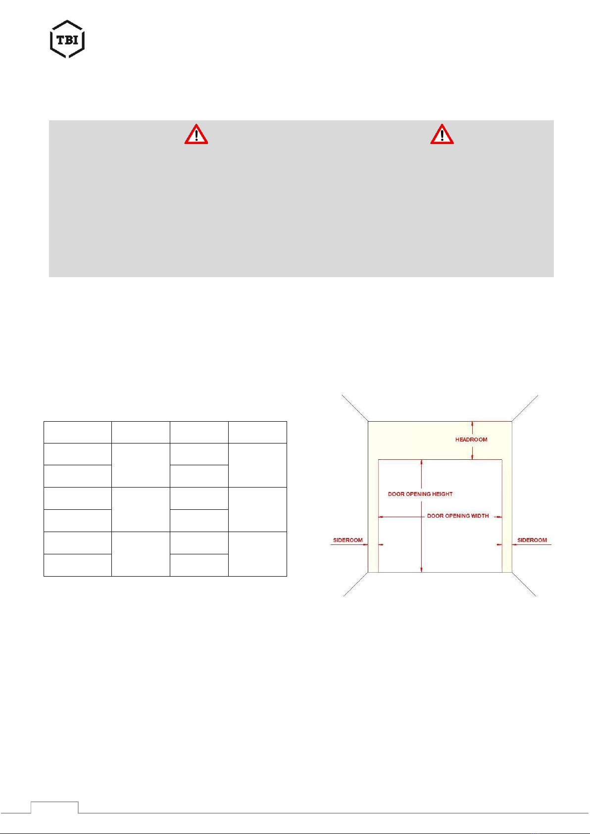
C. Check Table 1, and Figure A below, to determine amount of headroom, sideroom,
and back space room required for this particular door. Make sure NOW that all of
these clearances are available.
D. Suitable spring anchor pads or other anchorage for shaft bearings must be
provided. All spring or bearing anchor pads must be flush with and not extend
into the room any further than the jambs. Are pads now in place, or can they be
provided for as you progress?
E. Jamb must be plumb and solidly attached to the building. Floor must be level, or
exact grade line established before you start!
Table 1
Configuration
Headroom
Sideroom
Backspace
Standard Lift
Manual
450mm
175mm
DOH
+450mm
Standard Lift
Motor Side
300mm
High Lift
Manual
1700mm
175mm
DOH –
Amount of lift
+ 670mm
High Lift Motor
Side
300mm
Vertical Lift
Manual
DOH +
200mm
175mm
Up to
600mm
Vertical Lift
Motor Side
300mm
IMPORTANT SAFETY NOTICE
1. Operate door only when properly adjusted and free of obstructions.
2. Door is constantly under extreme spring tension. Repairs and adjustments, especially to cables and spring assembly, can be
hazardous and should be performed by qualified door service people only.
3. Do not permit children to play with the garage door or electric controls.
4. If door is now, or later becomes, electrically operated, pull down rope MUST be removed.
5. Avoid standing in open doorway or walking thru doorway while electrically operated door is moving.
6. Should door become hard to operate or completely inoperative, it is recommended that a qualified door agency be contacted.
The foregoing safety notice has been approved and recommended by the National Association of Garage Door Manufacturers
(NAGOM).

TRU-THERM™INSTALLATION & OWNERS MANUAL
5
Installation Instructions
Step 1- Fit Door Opening Seal
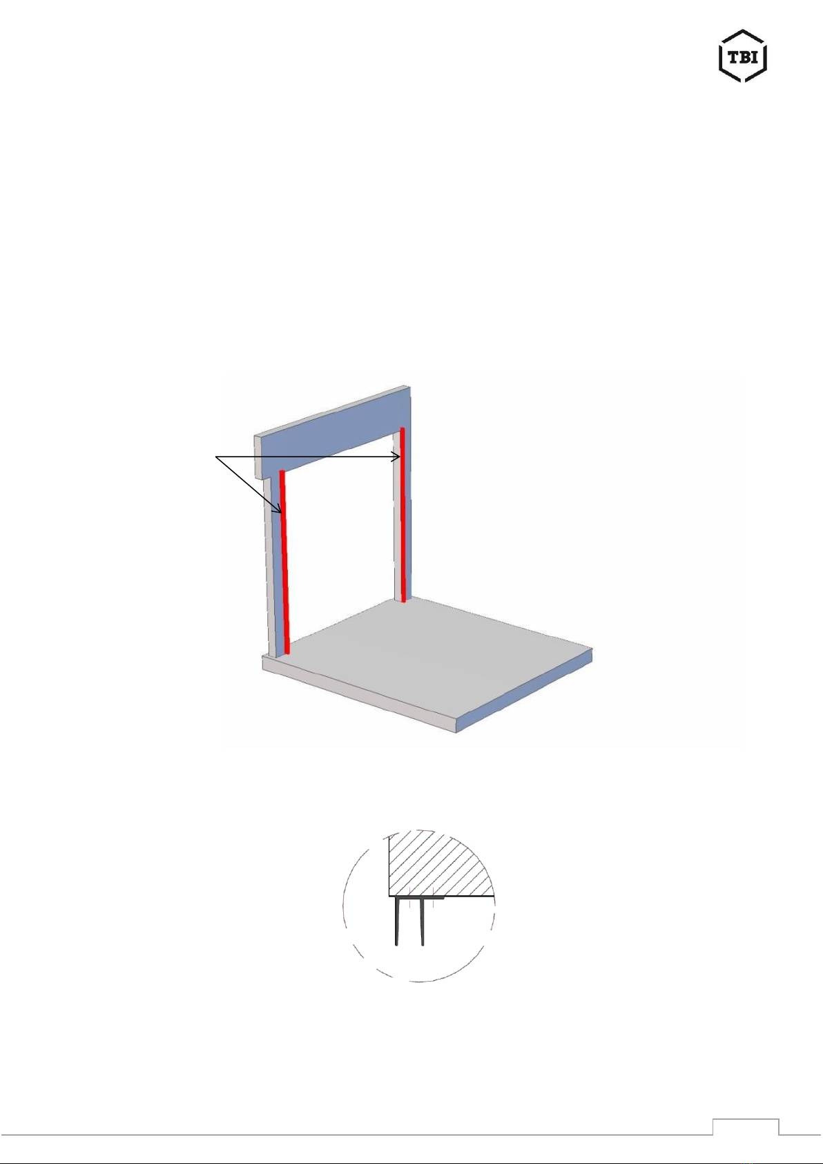
•The Door Opening seal supplied with your door kit should be fixed to the sides of
the door opening as shown below in figures B and C.
•Extreme Caution must be taken when attaching the seal on or around an
electric heat trace. Door tracks may also need to be packed off the wall.
•It is recommended that the seal is attached in one continuous length to finish
100mm above the lintel to ensure the best possible seal is obtained.
•TRU-THERM™Doors are manufactured with a standard overlap of 50mm on each
side.
Door seals
FIGURE B
FIGURE C

TRU-THERM™INSTALLATION & OWNERS MANUAL
6
Step 2- Prepare Bottom Panel
•Locate the bottom door panel with the weather seal and bottom brackets already
attached. See figure D below.
•Two rollers should be fitted to the bottom brackets along with the axle spacers
provided.
•IMPORTANT: You must use the 10mm spacer to minimise sideways movement of
the 2 bottom rollers!
•Locate four side hinges and attach two on each top corner of the bottom panel.
Use the gold 1/4” self-tapping tek screws provided.
•If door has Cable Break Safety Devices, these will need to be fitted in place of the
bottom wheel brackets shown below.
Axle Spacer - MUST BE FITTED ON EACH SIDE! Bottom wheel bracket
FIGURE D

TRU-THERM™INSTALLATION & OWNERS MANUAL
7
Step 3- Set up Bottom Panel and Tracks
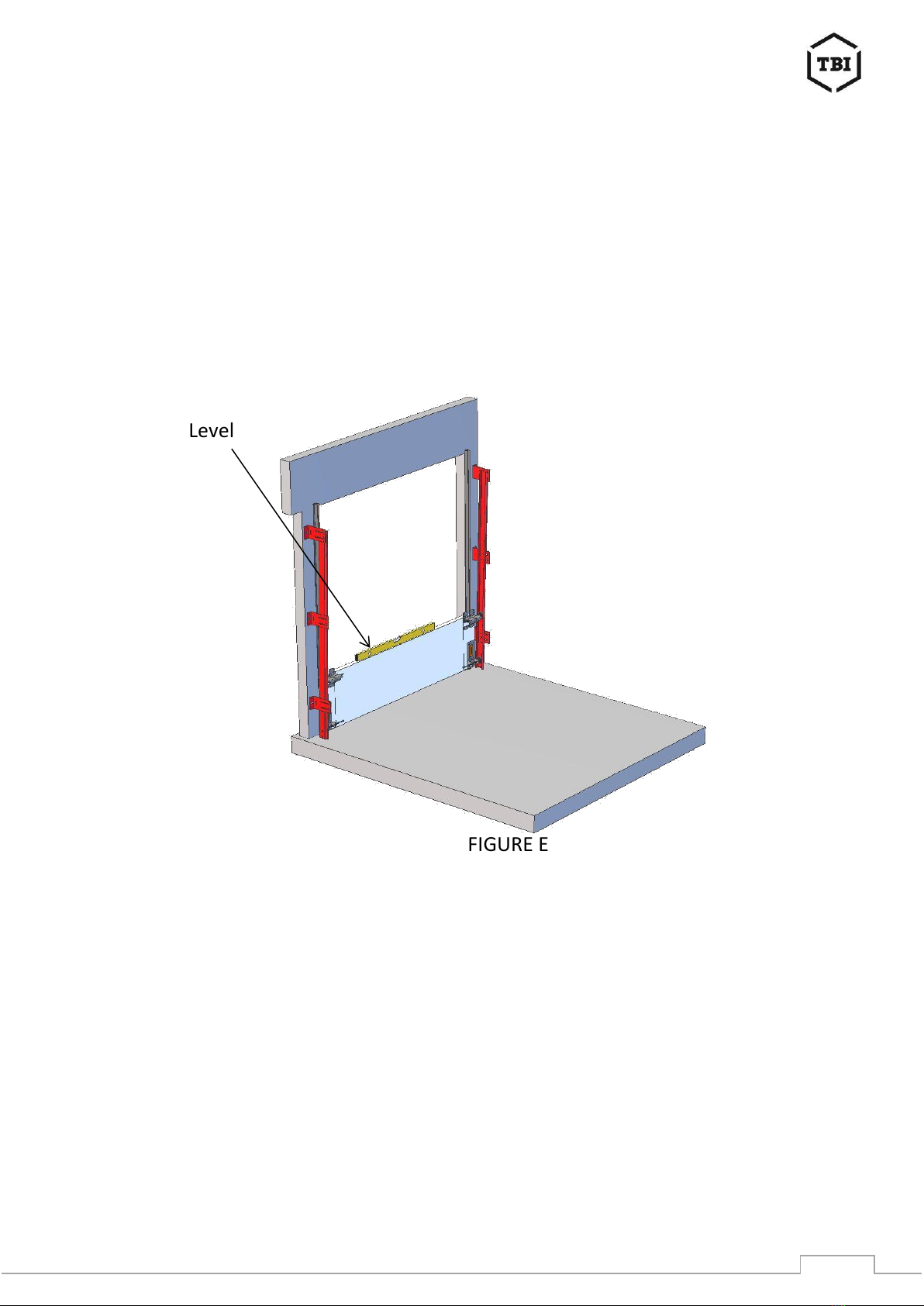
•Centre and level the Bottom door panel in the opening as shown in figure E
below. The panel will overlap the opening by 50mm each side.
•Temporarily attach the vertical tracks to the door jambs using the TL190 brackets
which are attached to the pre-drilled holes in the tracks using the M8x16 dome
head bolts and flange nuts, and then fastened to the wall. The bottom wheel
should be hard in against the spacer to locate the bottom end of the track.
Level
FIGURE E

TRU-THERM™INSTALLATION & OWNERS MANUAL
8
•It is very important that the top of each track is at the same level (shim if
necessary). See table below.
Door Type
Lintel to top of lower/vertical track
Standard Lift
180-190mm below lintel
High Lift
Amount of lift-380= measurement above lintel
Vertical Lift
200-210mm above lintel
•Ensure the tracks are angled further apart at the top than at the bottom to ensure
the door is guided to a central location as it closes. See Figure F below.
Dimension B should be: Dimension A plus 20mm (10mm each side).
•Also ensure the tracks are angled back as shown in Figure G below. Dimension D
should be: at least Dimension C plus 25mm; or as far back as the slots in the top
TL bracket will allow. If the tracks are not angled back, the door seals will be
rubbing all the time.
B
A
FIGURE F FIGURE G

TRU-THERM™INSTALLATION & OWNERS MANUAL
9
Step 4- Install Remaining Panels
•Install the door panels as shown below in Figure H.
•The top panel may be installed now or may wait until step 10 (installer
preference). There should be 20mm clearance between the top panel and the
lintel.
•Install side hinges onto left side of panel by screwing through pre-drilled holes in
end caps, install roller into vertical track, then rotate the panel into position and
stack. Then align panels and secure right hand hardware. (Screws will penetrate
reinforcing struts in panel- see Figure H on next page.)
FIGURE H

TRU-THERM™INSTALLATION & OWNERS MANUAL
10
Step 5- Fit Intermediate Hinges
FIGURE I
•Intermediate hinges should now be fitted to the door with a maximum spacing of
1000mm. See Figure I above. The hinge screws will penetrate the continuous
reinforcing strips as shown in figure I (Detail A).
•Panel strengthening struts (top hat purlins) will be supplied with all doors over
4000mm wide. The first strut should be fixed to the bottom panel and the rest
spaced evenly thereafter.
Indice
Altri manuali TBI Sistema di sollevamento
Manuali Sistema di sollevamento popolari di altre marche

Genie
Genie Z-60/34 Manuale utente

Screen Technics
Screen Technics INTERFIT Vertical Up Lift Manuale utente

Mortuary Lift
Mortuary Lift ULTIMATE 1000 Manuale utente

Custom Equipment
Custom Equipment Hy-Brid 3 Series Manuale di programmazione

Custom Equipment
Custom Equipment Hy-Brid Lifts 2 Series Manuale di programmazione

Hy-Brid Lifts
Hy-Brid Lifts HB-P3.6 Manuale di programmazione