
TECO 58A Manuale utente

Automotive Equipment
Automotive Equipment
Teco Srl - Via Pio La Torre, n°10
42015 Correggio (RE) Italy
www.teco.it - www.tecoautomotive.com
www.youtube.com/user/TECOsrl
Telephone: +39.0522.631562
Fax: +39.0522.642373
E-mail: teco@teco.it
Instruction Manual EN
TYRE-CHANGER
TECO 58A
Version 1.3 -April 2016

EC DECLARATION OF CONFORMITY
WE,
Teco Srl
Via Pio La Torre 10
42015 Correggio (RE)
Italy,
DECLARE UNDER OUR SOLE AND EXCLUSIVE RESPONSIBILITY THAT THE MACHINE:
TYPE:
tyre changer
MODEL:
SERIAL No.:
serial number
TO WHICH THIS STATEMENT REfERS AND fOR WHICH WE HAVE PREPARED AND HOLD THE RELATIVE TECH-
NICAL BOOkLET, COMPLIES WITH THE BASIC REqUISITES DEfINED BY THE fOLLOWING EUROPEAN UNION
DIRECTIVES:
- 2006/42/EC;
- 2014/35/EU;
- 2014/30/EU;
- 2011/65/EU.
THE fOLLOWING HARMONISED STANDARDS HAVE BEEN APPLIED TO VERIfY COMPLIANCE WITH THE fOL-
LOWING DIRECTIVES:
EN ISO 12100:2010; EN 60204-1:2006/AC:2010; EN 61000-6-2:2005/AC:2005;
EN 61000-6-3:2007/A1:2011/AC:2012
Correggio, 01/04/2016
TECHNICAL DIRECTOR
Ing. Mauro Barbetti
THE TECHNICAL DOSSIER RELATIVE TO CONSTRUCTION WILL BE kEPTAND WILL BE RENDERED AVAILABLE
BY ING. MAURO BARBETTI, C/O TECO SRL, VIA PIO LA TORRE , 10 42015 CORREGGIO (RE) ITALY.
IMPORTANT:THIS DECLARATION SHALL NO LONGER APPLY If CHANGESARE MADE TO THE PRODUCT WITH
RESPECT TO ITS CONfORMATION AT THE TIME Of SALE OR If CHANGES ARE MADE TO THE COMPONENTS
WITHOUT THE PRIOR AUTHORIZATION Of THE MANUfACTURER, OR IN THE CASE Of NON-COMPLIANCE
WITH THE INfORMATION CONTAINED IN THE USER MANUAL.
THE MODEL fOR THIS DECLARATION COMPLIES WITH WHAT IS SET fORTH IN EN ISO/IEC 17050-1 AND EN
ISO/IEC 17050-2

ENGLISH • Instructions manual
3TECO 58A
®
Automotive Equipment
INDEX
1. GENERAL INFORMATION...........................................................................................................................4
2. TECHNICAL DATA .......................................................................................................................................4
3. GENERAL SAFETY REGULATIONS...........................................................................................................4
4. SAFETY DEVICES........................................................................................................................................5
5. TRANSPORT................................................................................................................................................5
6. INSTALLATION.............................................................................................................................................5
6.1 Installation place.....................................................................................................................................5
6.2 Unpacking ..............................................................................................................................................6
6.3 Workplace requirements ........................................................................................................................6
6.4 Electric hook up......................................................................................................................................6
7. IDENTIFYING WARNING SIGNALS ............................................................................................................7
8. FUNCTIONAL PARTS LAYOUT...................................................................................................................8
9. IDENTIFICATION OF CONTROLS.............................................................................................................10
10. WORKING POSITION...............................................................................................................................10
11. CORRECT OPERATION CHECKS...........................................................................................................11
12. OPERATION ........ ....................................................................................................................................12
12.1 Locking the wheel...............................................................................................................................12
12.2 Tubeless and Supersingle wheels......................................................................................................13
12.3 Tubed wheels.....................................................................................................................................18
12.4 Wheels with 3-piece split rings...........................................................................................................21
12.5 Wheels with 5-piece split rings...........................................................................................................23
13. OPTIONAL ACCESSORIES.....................................................................................................................27
14. ROUTINE MAINTENANCE.......................................................................................................................28
15. MOVING THE MACHINE..........................................................................................................................29
16. STORING..................................................................................................................................................30
17. SCRAPPING A MACHINE........................................................................................................................30
18. DATA ON SERIAL PLATE........................................................................................................................31
19. TROUBLE SHOOTING.............................................................................................................................31
20. FIRE-FIGHTING........................................................................................................................................32

4
ENGLISH • Instructions manual
TECO 58A
®
Automotive Equipment
1. GENERAL INFORMATION
rims from 14” to 46” (56” with SE-2 extension) and a maximum 2600 mm diameter.
Any other use is improper and therefore not authorized.
The manifacturer shall not liable for any injury to persons or damage to things caused by improper use of this machine.
KEEP THIS MANUAL NEAR THE MACHINE AND CONSULT IT AS NEEDED DURING OPERATIONS.
2. TECHNICAL DATA
Pump motor
3,3 - 4,4 kW
Gear-box motor
1,9 - 2,5 kW
Handles rim from - to
14” - 46” (56” with SE-2)
Max. wheel diameter
2600 mm (103”)
Max. wheel width
1500 mm (59,6”)
Max. wheel weight
2500 kg
Weight (with standard accessories)
1410 kg
LpA < 70 dB(A)
3. GENERAL SAFETY REGULATIONS
Operators must not make use of drugs or alcohol which could alter their faculties.
It is, however, essential to:
- Know how to read and understand the descriptions.
- Know the performances and characteristics of this machine.
- Keep unauthorized persons away from the operating zone.
- Make sure that the installation has been made in compliance with all the pertinent regulations and standards in force.
- Carefully read this manual and learn how to correctly and safely use the machine.
- Always keep this manual ready to hand in an easily accessible place and consult it when necessary.
WARNING!
Unauthorized variations or modications to the machine shall relieve the manufacturer from all liability
for any deriving damages or accidents.
In particular, removal or tampering with the safety devices represents a violation of the Labour Safety
regulations.

ENGLISH • Instructions manual
5TECO 58A
®
Automotive Equipment
4. SAFETY DEVICES
The tyre changer has a number of safety devices designed to guarantee the utmost
operator safety:
1. Check valve on the spindle opening hydraulic line (inside the swivel connector, see
g. B/1).
2. Pilot operated dual seal check valve (see Fig. B/2).
3. Pressure relief valve factory set at 130 bar ±5% (See
Fig. B/3).
This limits the pressure in the hydraulic circuit and ensure correct operation of the plant.
If the tyrechanger is equipped with theaccessory RC Radio
control the mobile control box is connected to the body
away and from working without seeing the machine.
CAUTION: Removing or tampering with the safety devices is in violation
of European safety regulations and releases the manufacturer from all
liability for damage caused by or related to such actions.
5. TRANSPORT
Shipping weight is 1610 kg.
The machine must be handled with a fork-lift truck with the forks positioned as shown
in the gure A/2.
6. INSTALLATION
6.1 INSTALLATION PLACE
Choose the place the machine is to be installed in compliance with current work place safety regulations.
B/1
B/2
B/3
A/2

6
ENGLISH • Instructions manual
TECO 58A
®
Automotive Equipment
WARNING!
The machine must not be operated in explosive environments.
6.2 UNPACKING
Keep the packing materials out of the reach of children as they can be a source of danger.
N.B.: Keep the packing for possible future transport.
6.3 WORKPLACE REQUIREMENTS
Maximum machine space requirements are 2820 X 2300 mm with a minimum
distance from walls as shown in the diagram B/4.
CAUTION! These measurements are also the tyre chang-
ers working range.
Persons other than specially trained and authorized
operators are expressly forbidden to enter this area.
1, Fig. A) with the
tool carrier arm (2, Fig. A3, Fig. A) closed
and the tool carrier slide (13, Fig. A) at its stop close to the arm.
FIXING THE MACHINE
The machine should be xed to the oor when the
wheels handled weigh more than 1000 kg.
expanding bolts.
feet as indicated by the arrows in Figure B/5.
Inserttheexpansion boltsinthedrilled holesandtighten
the screws all the way.
6.4 ELECTRIC HOOK UP
Before making any electric hook up, check to be certain that the mains voltage corresponds to that stamped on the volt-
age tag (attached to the cord near the tyre changer’s plug).
It is absolutely essential that :
- the system is equipped with a good grounding circuit.
- The machine is connected to a power supply line circuit breaker set for 30 mA.
B/4
600 mm
2500 mm
1500 mm
2500 mm
B/5
ENGLISH • Instructions manual
7TECO 58A
®
Automotive Equipment
- The power socket take is adeguately protected against
overcurrents with fuses or circuit-breakers with rated
values as shown in the table below.
Note the required power draw as highlighted on the data
Work on the electric system, even if minor, must be
done exclusively by professionally qualied personnel.
Manufacturer shall not be liable for any injury to
persons or damage to property caused by failure to
comply with these regulations and can cancel warranty
coverage.
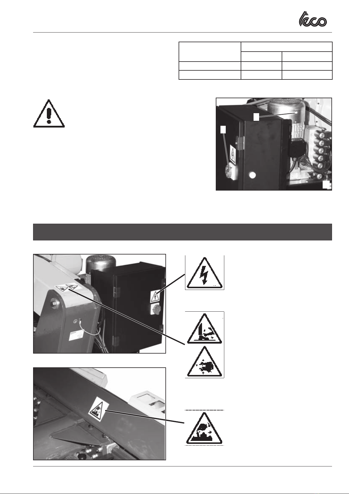
TURNING DIRECTION CHECKS
5, g. A) and check that
the hydraulic power pack motor rotation corresponds to the indicating arrow
(6, g. A).
POWER SUPPLY RATED CURRENT
FUSE SWITCH
230V - 3Ph - 50/60Hz 40A AM 40A
400V - 3Ph - 50/60Hz 25A AM 25A
7. IDENTIFYING WARNING SIGNALS
Code 4-402638
Code 4-402353
Code 4-402636
A
5
6
Feet-crushing hazard during turntable
turning or opering
Hand-crushing hazard between turntable
jaws.
Crushing hazard between turntable arm
and tyre changer body.

8
ENGLISH • Instructions manual
TECO 58A
®
Automotive Equipment
8. FUNCTIONAL PARTS LAYOUT
WARNING:
Unreadable and missing warning labels must be replaced immediately.
Do not use the tyre changer if one or more labels are missing.
Do not add any object that could prevent the operator from seeing the labels.
Use the code in this table to order labels you need.
1 - Lifting bracket
2 - Self-centering chuck holding arm
3 - Self-centering chuck
4 - Sliding table
5 - Main switch
8 - Upper joystick
9 - Turntable opening/closing switch
10 - Chuck anticlockwise rotation pedal
11 - 2nd-speed switch
12 - 2nd-speed pedals
13 - Carriage
14 - Tool holding arm
15 - Lower joystick
17 - Bead breaking disk
18 - Tool
19 - Tools replacement knob
20 - Chuck clockwise rotation pedal
21 - Manometer
22 - Jaw
Code 4-402637
Code 4-402635
Crushing hazard during tool holding arm re-
hoking.
Code 4-402926
is still mounted on the turntable.
Crushinghazardbetween turntable
and tool.
Wheel-faling hazard
Mind to the tool-holding arm during tilt-
ing or opering.

ENGLISH • Instructions manual
TECO 58A
®
Automotive Equipment
a
d
c
b
10
11
15
C
12
12
20
8
a
d
c
b
1
22 3
4
2
21
5
A
D
13
14
17
18
10
ENGLISH • Instructions manual
TECO 58A
®
Automotive Equipment
10. WORKING POSITION
The diagram B/8 illustrates the various working positions (A, B, C, D) referred to in the
following pages describing how to use the tyre changer.
Use of these positions ensures greater precision, speed and safety for those using the
machine.
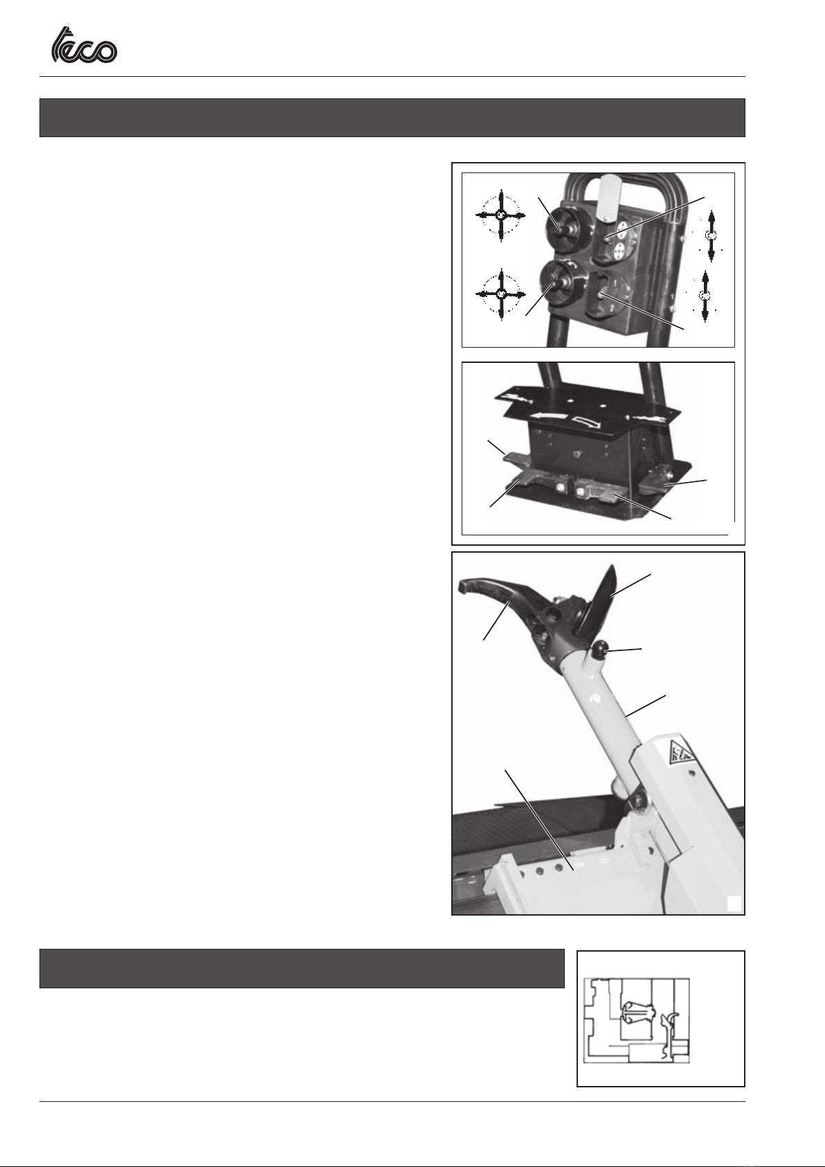
9. IDENTIFYING CONTROLS
The mobile control centre (g. C) enables the operator to work at
any position around the machine. On this mobile control centre the
following controls are located:
-The top joystick (8, g. C) which in position alifts the chuck arm and in
position bc
holder arm leftwards simultaneously (so they get nearer each other) and
inposition d
(so they get farther each to the other).
- bottom joystick (15, Fig. C): whenpulled upwardsa
-
wards bc
d
to starting position.
Note: chasbeen
-The chuck switch (9, g. C)
arm of the self-centering chuck (UN-LOCKING).
- The clockwise rotation pedal (20, g. C)
clockwise.
- The anticlockwise rotation pedal (10, g. C)
chuck anticlockwise.
- The second speed switch (11, Fig. C)
speed.
- The second speed pedals (12, Fig. C)
the turntable and tool holding arm (c and d of the upper joystick) and the
at double speed.
NOTE:
machine can be done with precision.
On the tyre changer there is olso a knob (19, Fig. D) which allows to
replace tools (for instance for mounting accessory TR2 Tubeless roller).
a
d
c
b
10
11
15
C
12
12
20
8
a
d
c
b
D
13
14
17
18
• D • C
• B
• A
B/8
Indice
Altri manuali TECO Smontagomme


