Toyostove Laser 73 Manuale utente
LASER CLEAN VENTED
MODEL
Laser 73 / Laser 73AT
CONTENTS
IMPORTANT
READ AND UNDERSTAND INSTRUCTIONS BEFORE INSTALLING OR USING HEATER.
RETAIN INSTRUCTIONS FOR FUTURE REFERENCE. CHECK LOCAL CODES FOR PERMITTED USE.
LASER CLEAN HEATING SYSTEM/VENTED HEATER
INSTALLATION AND OPERATION INSTRUCTIONS
SECTION A:
Specifications
Safety Features
SECTION B:
Safety Tips for Operation
SECTION C:
Fuel Guide
SECTION D:
Operating Controls and Part Names
SECTION E:
Operation
Before Ignition
Operation
Turning Heater Off
SECTION F:
Routine Maintenance
················································ 2
·············································· 3
································ 4
···················································· 5
················· 6
··········································· 9
·················································· 9
···································· 12
···································· 12
············································ 14
········································ 16
······················ 17
························· 17
········································ 19
·························· 22
············· 23
···················· 29
························································ 30
SECTION G:
Troubleshooting
SECTION H:
Long Term Storage
SECTION I:
Installation
Tools Needed for Installation
Standard Installation Parts
Accessary Parts
Safety Tips for Installation
Installation of Heater and Flue Pipe
Permanent Wiring Installation
SECTION J:
Fueling
(Type L)

SECTION A:
SPECIFICATIONS
Model:
Heater Efficiency:
Heat Rating:
Fuel Consumption:
Fuel System:
Fuel Type:
Dimensions (W × H × D):
(Includes drip tray)
Weight:
Vent Pipe Hole:
Maximum Length of Vent Pipe System:
Electrical Rating:
Typical Room Size (3):
Laser 73
92% (1)
High - 40,000 BTU/h (11,733 Watts)
Med - 27,000 BTU/h (7,920 Watts)
Low - 15,000 BTU/h (4,400 Watts)
High - 0.301 gal/h (1.139 L/h)
Med - 0.203 gal/h (0.768 L/h)
Low - 0.113 gal/h (0.428 L/h)
External tank (2)
ASTM No.1-K Kerosene Only
30“× 27-1/2“× 16-3/4“
(76.2 × 68.8 × 42.5 cm)
88 lbs. (40 kg) Empty
2-3/4“~ 3“diameter
(7.0 - 7.5 cm)
10 ft. (3 m), 3 bends or less
120 Volts AC, 60 Hz
Preheat
-
280W
Burning
-
76W
1670 square feet (0°F)
2000 square feet (20°F)
(1)
(2)
(3)
Heat and vaporized water are produced by the combustion process of this kerosene heater. This rating
does not take into account heat loss due to condensation of water vapor.
External tank to be purchased from local suppliers.
0°F Heat Load =24 BTU/ft2/hr
20°F Heat Load = 20 BTU/ft2/hr
Room size for which this heater is suitable will vary depending on outside temperature, house
insulation, window size, and other factors.
2
SAFETY FEATURES
Your Laser 73 is equipped with the following safety features. Please familiarize yourself with these features.
When your heater is extinguished due to a safety mechanism, be sure to identify and correct the problem.
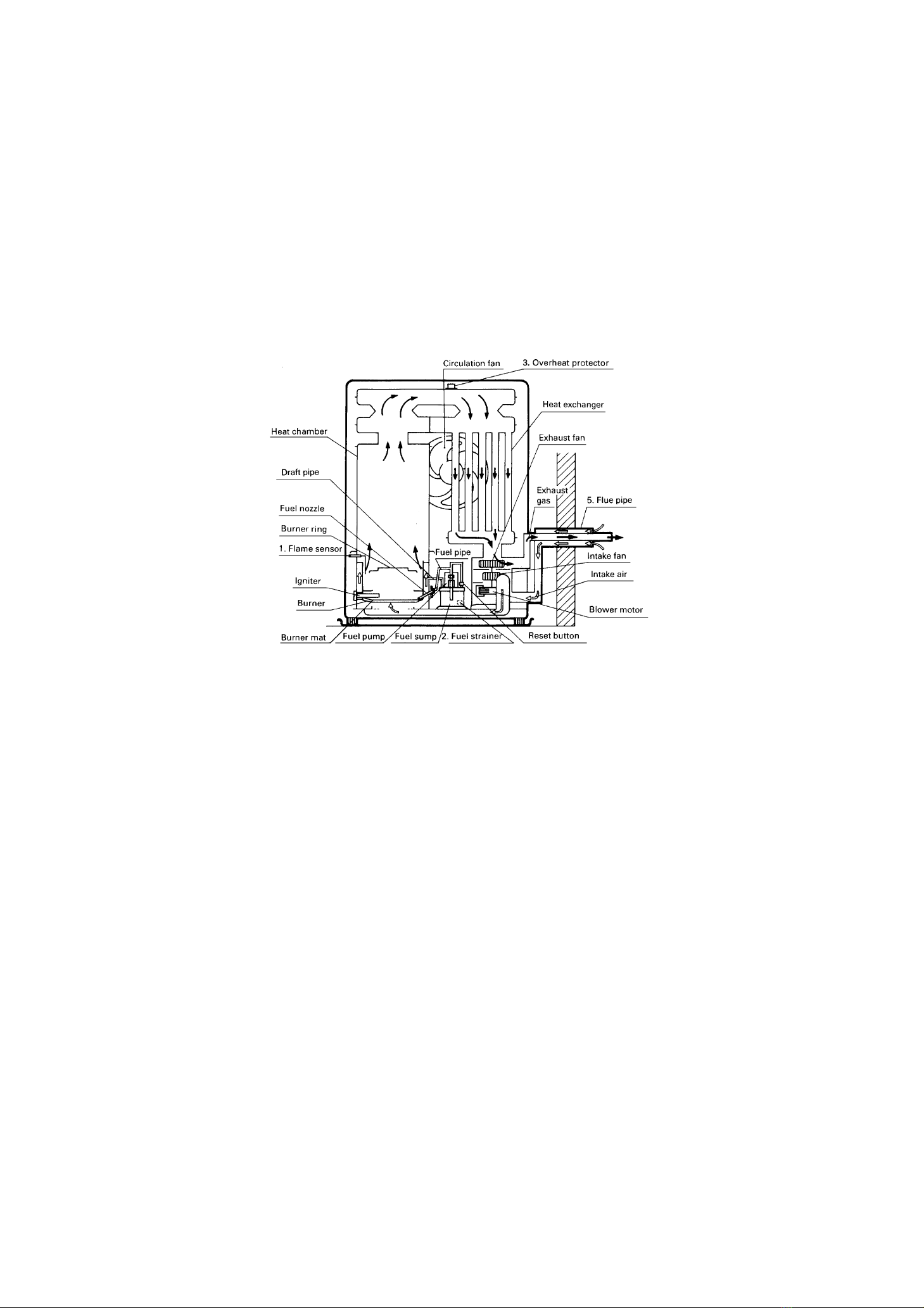
Flame Sensor
Heater will automatically stop all operations if ignition fails or if flame fails during combustion, in order
to prevent fuel overflow. Error code will be displayed on the digital indicator.
Fuel Strainer
Special strainer catches any dirt or impurities present in the fuel before it is sent to the burner.
Overheat Protector
Automatically stops all operations if heater cabinet reaches abnormally high temperature due to motor
malfunction or abnormal combustion, in order to prevent fire.
Power Failure Recovery System
If power fails during heater operation, heater will turn off. When power resumes, heater will
automatically reignite to maintain the selected room temperature.
Fully Vented System
Flue pipe system provides outside air for combustion and vents all combustion products to the
outdoors.
Fusible Link Valve
If a household fire should occur, bringing the fuel line or heater to extremely high temperatures, the
fusible link valve will stop the fuel supply to the burner. This will prevent the fuel supply from the
external tank continuing to flow into the house.
1.
2.
3.
4.
5.
6.
3
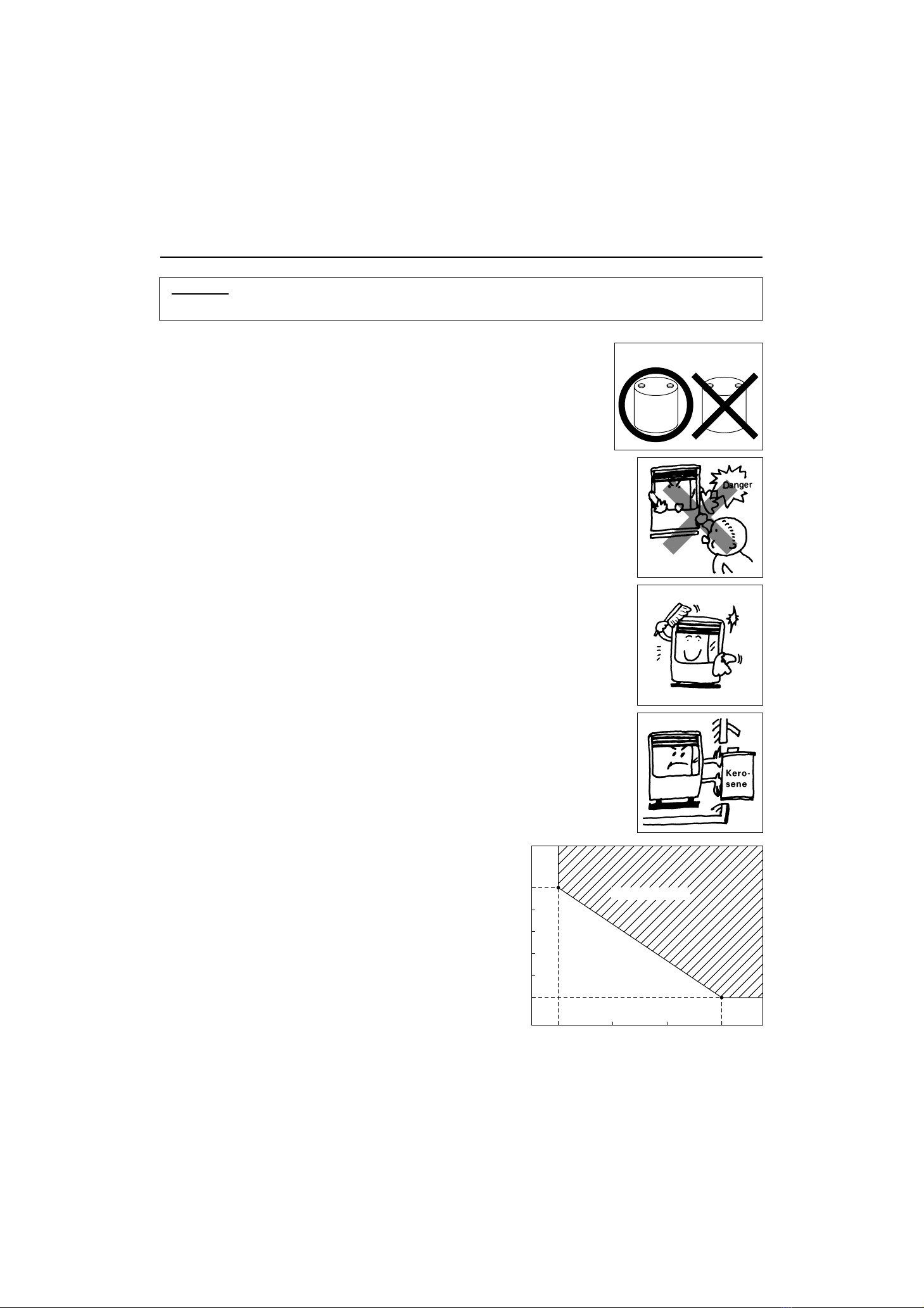
CAUTION:
0 204060
-20 A
B
Room Temperature (˚F)
Outside Temperature (˚F)
-25
-30
-35
-40
-45
SECTION B:
SAFETY TIPS FOR OPERATION
If outside temperature -20°F
than room temperature has to be 0°F or above
If outside temperature -45°F
than room temperature has to be 60°F or above
Point A:
Point B:
RIGHT
KEROSENEKEROSENE
WRONG
GAS
Heater and vent pipe system must be properly installed before operation.
Please follow instructions under “Installation”, Section I.
Never use any fuel other than clear or red colored kerosene (ASTM No. 1-K
Kerosene). NEVER USE GASOLINE. Use of gasoline can lead to
uncontrollable flames, resulting in destructive fire.
1.
Due to high surface temperatures, keep heater away from children, furniture
and clothing while in operation (See Page 24).
2.
To prevent abnormal operation and prolong heater life, be sure to perform
routine maintenance (See Pages 12
-
13).
3.
Never store or transport kerosene in other than a metal or plastic container
that is (1) acceptable for kerosene, (2) non-red in color, and (3) clearly
marked, “KEROSENE”. Never store kerosene in the living space.
4.
Operating Temperature Range
Use heater within the range of temperatures
indicated in the right figure.
5.
Operating Range
4
GAS
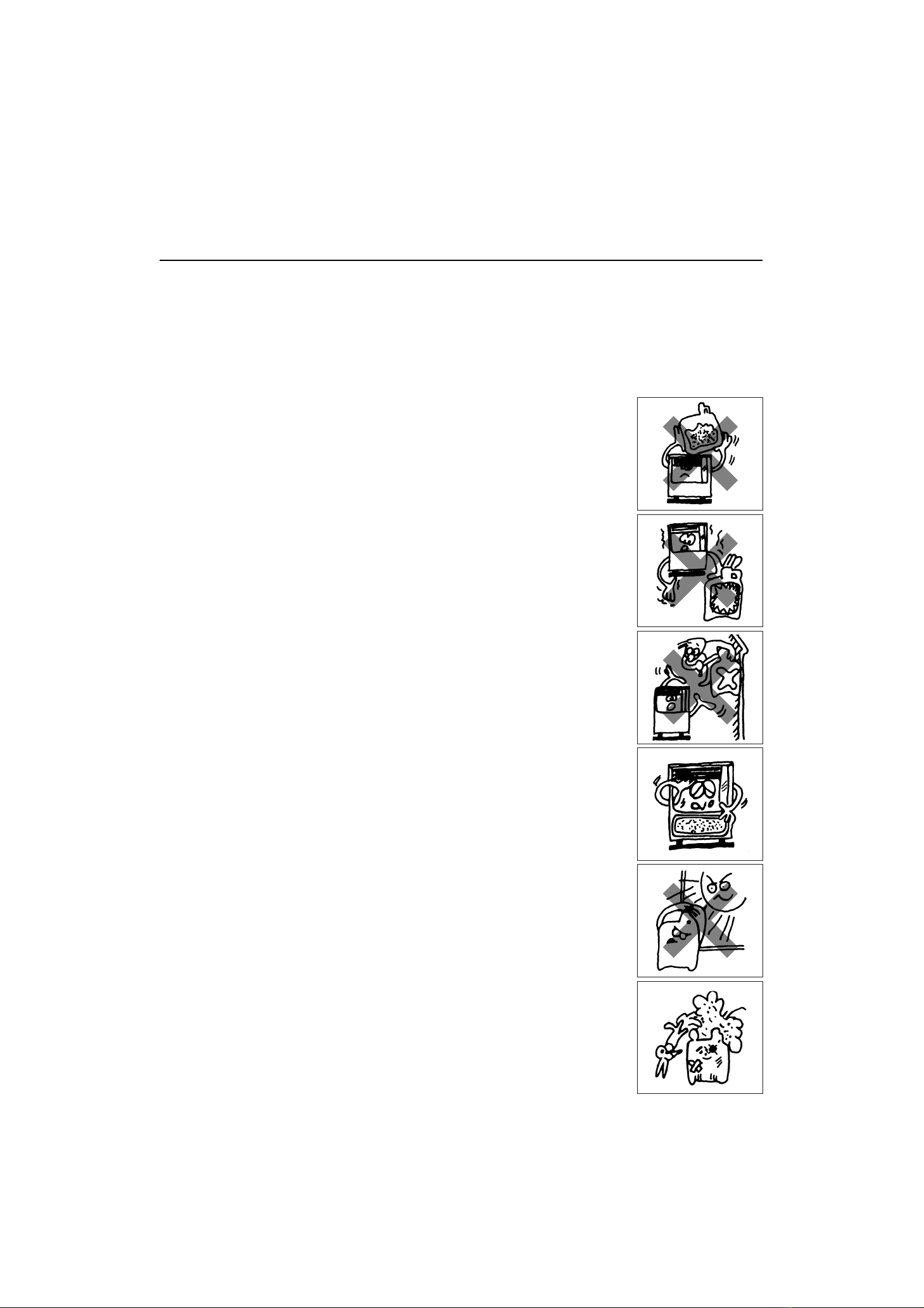
SECTION C:
FUEL GUIDE
The Toyostove Laser 73 is designed for use with clear or red colored No.1-K kerosene only. Use of low-
quality kerosene will cause burner performance to drop, leading to abnormal combustion and reduced
heater life.
Purchase only 1-K kerosene in non-red cans reserved exclusively for kerosene and marked accordingly with
the word “KEROSENE”. Always store your kerosene in a separate area from where you store gasoline for
your power equipment to avoid accidental use of gasoline in your heater.
Crystal clear or red colored, high-quality KEROSENE, ASTM
No.1-K.
Kerosene free of contaminants, water or cloudiness.
Gasoline, alcohol, white gas, camp stove fuel or additives.
Yellow or sour-smelling fuel.
Store in a clean container, non-red in color, clearly marked
KEROSENE.
Store away from direct sunlight, heat sources or extreme tempe-
rature changes.
In a glass container, or one that has been used for other fuels.
For longer than six months. Begin each heating season with
fresh kerosene; discard at the end of season.
In the living space.
¡Excess tar deposits on burner and flue pipe
¡Incomplete combustion
¡Reduced heater life
What to Buy . . .
ALWAYS :
ALWAYS :
NEVER :
NEVER :
How to Store It . . .
ALWAYS :
ALWAYS :
NEVER :
NEVER :
NEVER :
Why It is Important . . .
Pure, clean kerosene is essential for safe and efficient heater operation. Poor
quality or contaminated kerosene can cause:
Use of a highly volatile flammable fuel such as gasoline can produce
uncontrollable flames, creating a severe fire hazard.
5
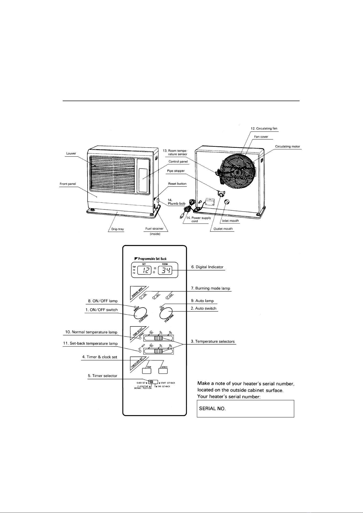
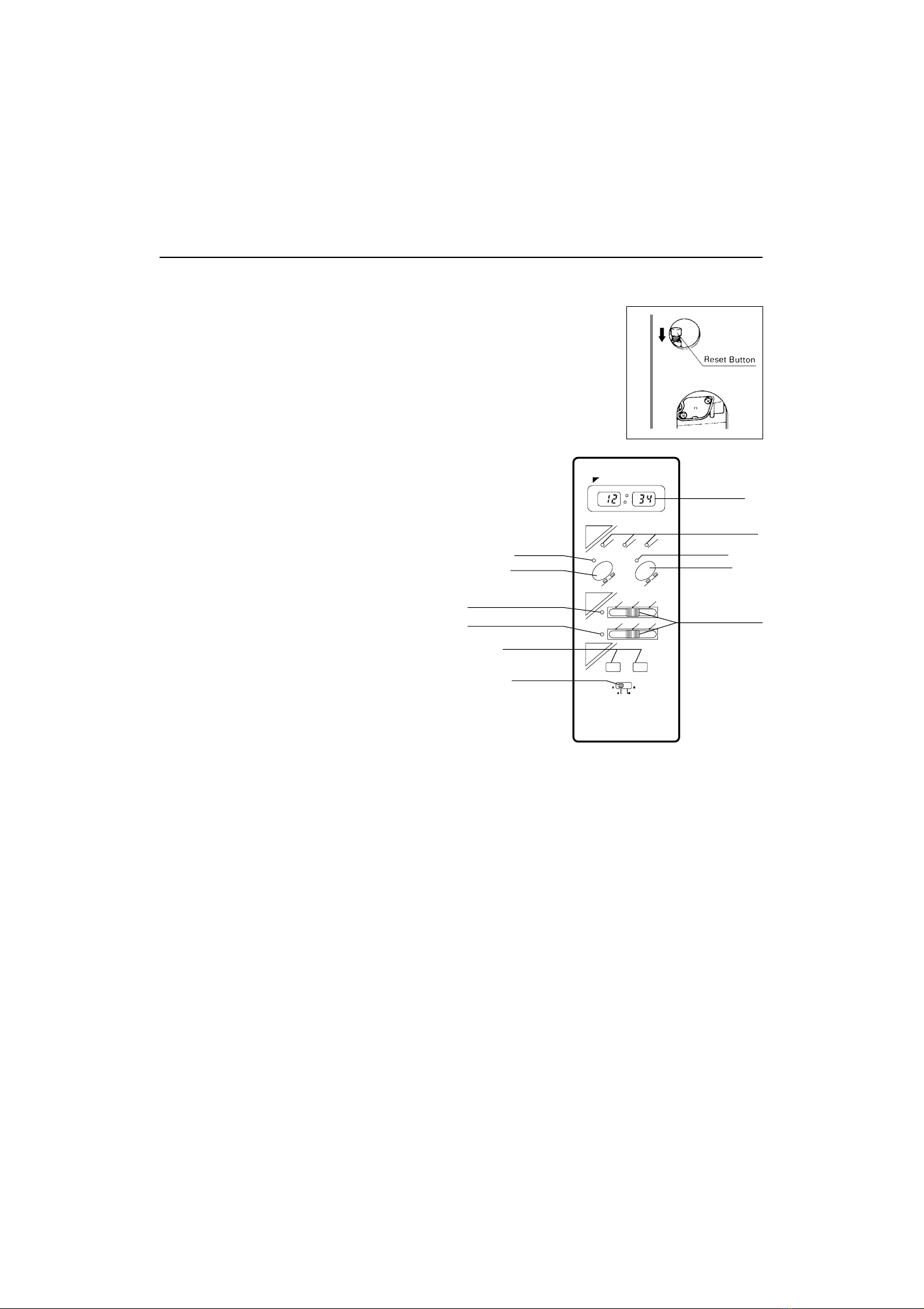
Before using heater, familiarize yourself with the following operating controls and part names.
SECTION D:
OPERATING CONTROLS AND PART NAMES
6

Main switch which turns heater on and off. When switched on,
heater begins operation and combustion starts after preheat period.
The switch turns automatic operation modes on and off which
have been programmed into timer.
“NORMAL”and “SET-BACK”temperature selectors allow user to
select desired temperature during manual or automatic operation.
Timer and clock set modes can be set by pressing hour or minute
buttons.
Clock, clock set, “SET-BACK”mode, start time set and end time
set can be selected by this switch.
Displays clock, set temperature, room temperature and error code.
Indicates whether heater is operating at high, medium or low
combustion.
Lights when heater is in operation and flashes when heater is in
prepurge or postpurge.
Lights when automatic operation is in use.
Lights when heater runs with manual or “NORMAL”mode of
automatic operation.
Lights when heater runs with “SET-BACK”mode of automatic
operation.
Three-speed motor supplies high-capacity warm air flow during
high combustion for heating room up quickly, and low or medi-
umcapacity warm air flow during low or medium combustion for
maintaining comfortable room temperature.
Constantly senses room temperature and supplies information to
heater so that desired room temperature can be maintained.
For use in 120V, AC electrical outlets only.
Allows user to check if heater is positioned evenly.
1. ON/OFF switch:
2. Auto switch:
3. Temperature selectors:
4. Timer & clock set:
5. Timer selector:
6. Digital indicator:
7. Burning mode lamp:
8. ON/OFF lamp:
9. Auto lamp:
10. Normal temperature lamp:
11. Set-back temperature lamp:
12. Circulating fan:
13. Room temperature sensor:
14. Power supply cord:
15. Plumb bob:
INDICATOR LAMPS
ON/OFF lamp
AUTO lamp
LOW lamp
MED lamp
HIGH lamp
NORMAL lamp
SET-BACK lamp
Flashing - Pre-heating, pre-purging and post-purging mode
Lit - Heater in operation
Flashing - Power loss of more than 10 seconds
Lit - Heater in operation at auto mode
Lit - Heater in operation at low combustion
Flashing - Pre-purging mode (without flame)
Lit - Heater in operation at medium combustion
Lit - Heater in operation at high combustion
Lit - Heater in operation at normal mode
Lit - Heater in operation at set-back mode
7
1
2
3
4
5
6
7
8
9
10
11
12
13
14
15
16
17
18
19
20
21
22
23
24
25
26
27
28
29
30
31
32
33
34
35
36
37
38
39
40
41
42
43
44
45
46
47
48
49
50
51
52
53
54
55
56
57
58
59
60
61
62
63
64
65
66
67
68
69
70
71
72
73
74
75
76
77
78
79
80
81
82
20478446
20479146
20475804
20479104
20450007
20474970
20478129
20479129
20478160
20479160
20478163
20479163
20478164
20479164
20475172
20478644
20475808
20478642
20478643
20478026
20478383
20475518
17185580
20474921
20474920
20478411
20475194
20475850
20475831
20475881
20474992
20475893
20478437
20478847
20478871
20475883
20475875
20475878
20475877
20478534
20478419
20478641
20478550
20475551
20475552
20478512
20478378
20478379
20478306
20478376
20478301
20478317
20477414
20478314
10005597
20475852
20478669
20478373
20479891
20474925
20475535
20478188
20474059
20478156
20479156
20474050
20474039
20474057
20475553
20474055
20450120
20478090
20475874
20474272
20475171
20474983
20478613
20478366
20478683
20479294
20479298
20479197
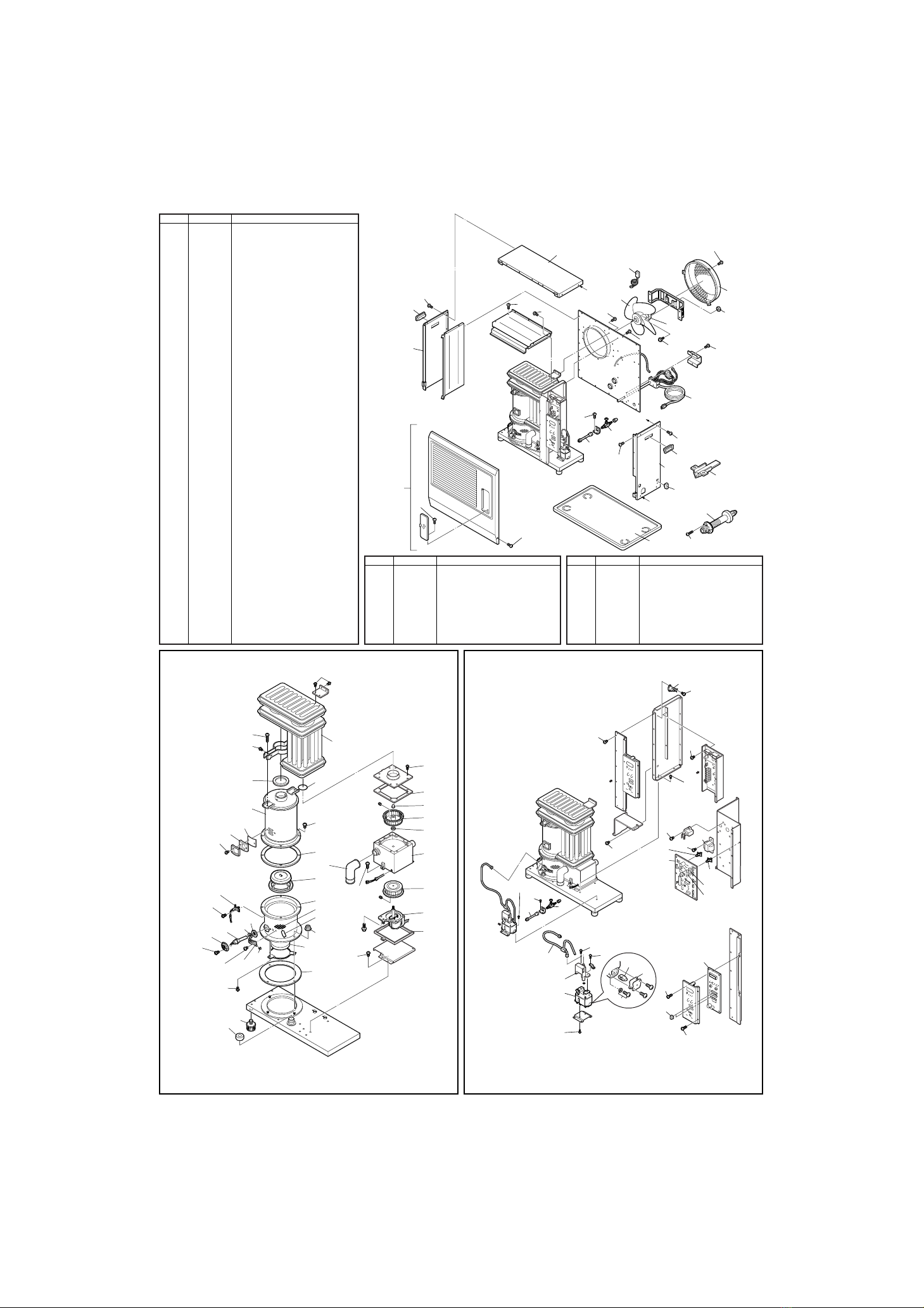
Front panel assembly
Front panel assembly (L-73AT)
Carrying handle
Carrying handle (L-73AT)
Plumb bob
Adjustable leg
Drip tray
Drip tray (L-73AT)
Top plate
Top plate (L-73AT)
Right side panel
Right side panel (L-73AT)
Left side panel
Left side panel (L-73AT)
Fan cover
Heat exchanger
Heat chamber assembly
Burner assembly
Burner ring
Fuel nozzle
Fuel nozzle gasket
Igniter
Igniter gasket
Igniter guide gasket
Igniter cover
Primary flame rod
Burner gasket
Burner insulating pad
Mica window
Peep window gasket
Joint packing
Heat chamber gasket
Blower motor assembly
Blower motor assembly with case
Blower motor exhaust fan
Blower motor intake fan
Blower motor case gasket
Rubber mat
O-ring (ø75)
Fuel sump
Fuel pump
Fuel pipe assembly
Inlet strainer
Drain screw with O-ring
Strainer gasket
Main circuit board
Fuse A
Fuse B
High limit switch
Indicator lamp circuit
Knob for temp selector
Transformer
PCB support
PCB support (S)
Fusible link valve
Leveler fuel pipe
Circulation fan motor
Thermistor
Flue pipe
Oil catch
Power supply cord
Screw 1X
Holder A
Screw 1S
Screw 1Y (L-73AT)
Screw C (=20478091)
Insulator A
Flange nut
Screw 1P
Screw O
Screw for igniter unit
Screw 1T
Washer for blower motor
Screw M
Circulation fan
Outlet adapter
Burner mat
Air damper (ø25)
Draft tube
Instruction manual
Carton
Carton (L-73AT)
REF # PART # PART NAME
REF # PART # PART NAME REF # PART # PART NAME
3,4
13,14
66
66
9,10
a
64,65
58
67
15
66
66
75
66
66 70
57
b
61
64,65
3,4
11,12
5
60
55
56
66
66
a
74
59
7,8
64,65
63
1,2
B
A
49 71
66
66
66
66
66
DETAIL A
66
52
53
54
46
48
47
DETAIL B
66
66
50
51
DETAIL C
69
45
44
43
70
41
40
70
42
C
56 55
66
66
36
34
73
35
68
37
66
76
66
19
16
39
72
32
62
66
31
17
29
30
66
66
66
38
33
18
68
28
27
77
79
26
24
23
66
6
78
22
25
66
66
21
20
66
8
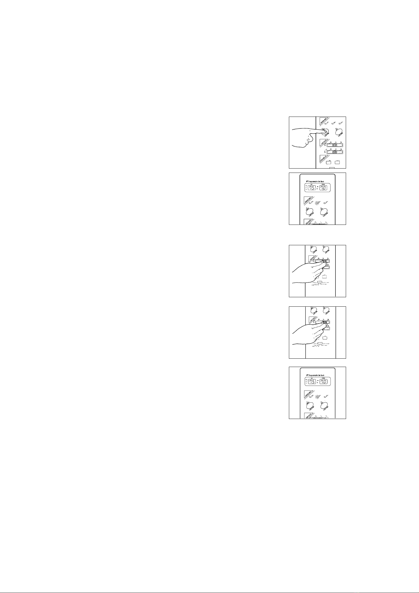
BEFORE IGNITION
4.
OPERATION
SECTION E:
OPERATION
MANUAL OPERATION
Open the Valve(s)
Open the valve(s) of the external fuel tank.
Start the Fuel flow
If using heater for the first time, or after heater has been out of fuel, press
the red reset button once for a period of one second in order to send fuel
to the fuel sump.
Plug in the Heater
Plug heater into a 120V AC electrical outlet.
Note: Do not connect to an outlet shared with other appliances.
C. Position timer selector to “CLOCK/TEMP (NORMAL POSITION)”after clock setting is completed.
Current time will be shown on digital indicator.
In the event of a power failure over ten (10) seconds, all clock and timer settings are cancelled.
Digital indicator will flash “PM 12:00”when heater is off, or “AUTO”lamp will flash when
heater is on and in automatic operation, after is power is restored. However, no indications
when heater is in manual operation. At this point, you need to reset all time and set-back
functions.
Note:
“MANUAL”operation means that the set-back will not be in use but in ”NORMAL”mode.
Operation of the heater is under the direct control of the user (“AUTO”switch is off). Heat output will,
however, be automatically adjusted in accordance with the room temperature registered by the
temperature sensor.
Operation of Laser Heater can be controlled manually by the user - “MANUAL”operation (NORMAL mode
only) or run automatically by the programming - ”AUTOMATIC”operation (NORMAL mode and SET-BACK
mode).
3.
Set Clock
Important: Clock on the heater always
must be set to current time.
A.
Position timer selector to “CLOCK SET”.
B. Press “HOUR”and “MINUTE”button
of TIMER/CLOCK SET to correct time.
Important: Check for the AM or PM
indicators, to insure the
correct time.
4.
Note: Make sure there is no fuel leakage from the fuel line or joints.
Also make sure fuel tank is not too high. See installation instructions.
1.
2.
“HOUR”or “MINUTE”button will
change the time every one (1)
unit. Holding the button
continuously will cause the time
to change rapidly.
Note:
BURNER
LOW
MED
HIGH
BURNINGMODE
TEMPSELECT
TIME/CLOCKSET
OFF
NORMAL
SET·BACK
ON
AUTO
OFF ON
HOUR MINUTE
START SET-BACK
50°F
10°C
70
21
90
32
50°F
10°C
70
21
90
32
SET
TEMP
AM
PM
ROOM
Programmable Set Back
END SET-BACK
CLOCK SET
CLOCK/TEMP
(NORMAL POSITION)
8. ON/OFF lamp
6. Digital Indicator
7. Burning mode lamp
9. Auto lamp
2. Auto switch
3. Temperature selector
1. ON/OFF switch
10. Normal temperature lamp
11. Set-back temperature lamp
4. Timer & clock set
5. Timer selector
9
1. Select Manual Operation
Press the “AUTO”switch to “OFF”position.
2. Turn Heater ON
A. Push in ON/OFF switch to “ON”position. The current room temperature
and the set temperature will be shown on the digital indicator. ON/OFF
lamp will start to flash and then blower motor and ignition will start.
Note: Heater will not start when room temperature is higher than the
desired temperature setting.
B. Burning mode lamp “MED”will start to flash after approx. 3 - 9 minutes
and ignition will take place. (*) After ignition, burning mode lamp “MED”
will change from flashing to continuous. And, after 10 seconds, burning
mode lamp will turn to “LOW”and heater will start “LOW”burning mode.
Circulation fan will turn on after approx. 3 minutes.
Note: (*) Pre -heating depends on the room temperature.
Room temperature: below 34°F - 9 minutes
34°F - 61°F - 6 minutes
over 61°F - 3 minutes
C. Heater will operate at “LOW”or “MED”burning mode for approx. 6 min-
utes after ignition, regardless of temperature control setting. Heater will
not go into “HIGH”burning mode while the prepurging is in effect. After
this period, output can be adjusted as desired by using the ”NORMAL”
temperature selector as directed in following instructions.
3. Adjusting Room Temperature
A. Slide “NORMAL”temperature selector to set the room temperature
desired. The temperature control should be set at the position you find
most comfortable.
Note: Desired temperature setting will be displayed on the digital
indicator when you set the room temperature.
Note: The scale on temperature selector is just for your reference. The
figures on the digital indicator and on the scale may not match
exactly; This is normal.
B. Burning mode will be regulated automatically in accordance with the room temperature registered by
the room temperature sensor. Heater will be operated at “HIGH”burning mode until room tempera-
ture reaches the selected temperature level.
C. When room temperature reaches the selected setting, heater will automatically shift to “MED”or
“LOW”burning mode to maintain the desired temperature.
When room temperature exceeds the selected setting by approx. 4°F, the heater will automatically
shut off. As room temperature drops, the heater will automatically re-start to maintain the desired
temperature.
10
Altri manuali per Laser 73
4
Questo manuale è adatto per i seguenti modelli
1
Indice
Altri manuali Toyostove Sistema di riscaldamento

Toyostove
Toyostove Laser 56 F Manuale utente

Toyostove
Toyostove Laser 73AT Manuale del proprietario

Toyostove
Toyostove Laser 30 Type B Manuale utente

Toyostove
Toyostove Laser 30 Type B Manuale utente

Toyostove
Toyostove Laser 30 Manuale del proprietario

Toyostove
Toyostove Laser 56 Manuale utente

Toyostove
Toyostove Laser 56 Type I Manuale utente

Toyostove
Toyostove Laser 30 Type B Manuale utente

Toyostove
Toyostove Laser 73 Manuale utente

Toyostove
Toyostove Laser 56 Manuale utente


