
TrueNAS R Series Manuale utente
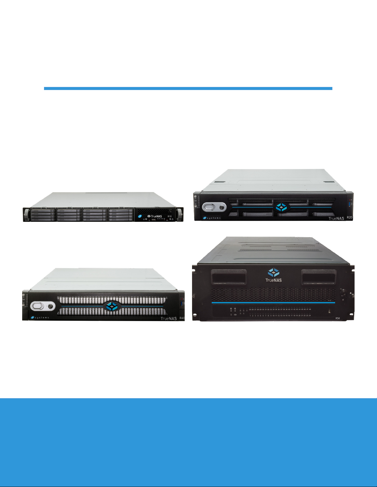
TrueNAS®R-Series Basic Setup Guide
Version 1.32

Contents
1 Introduction ������������������������������������������������������������������������������������������������������������������������ 1
1�1 Safety �������������������������������������������������������������������������������������������������������������������������� 1
1�2 Requirements ���������������������������������������������������������������������������������������������������������������� 1
2 R10 Components ������������������������������������������������������������������������������������������������������������������ 2
2�1 Front Ports and Indicators ������������������������������������������������������������������������������������������������� 3
2�2 Rear Components and Ports ����������������������������������������������������������������������������������������������� 3
3 R20 Components ������������������������������������������������������������������������������������������������������������������ 4
3�1 Front Ports and Indicators ������������������������������������������������������������������������������������������������� 5
3�2 Rear Components and Ports ����������������������������������������������������������������������������������������������� 5
4 R40 Components ������������������������������������������������������������������������������������������������������������������ 7
4�1 Front Ports and Indicators ������������������������������������������������������������������������������������������������� 8
4�2 Rear Components and Ports ����������������������������������������������������������������������������������������������� 8
5 Rack the R10, R20, or R40 ������������������������������������������������������������������������������������������������������� 9
5�1 Install Chassis Rails ���������������������������������������������������������������������������������������������������������� 9
5�2 Install Rack Rails ������������������������������������������������������������������������������������������������������������ 10
5�3 Mount the System in the Rack �������������������������������������������������������������������������������������������� 10
6 Install or Replace Drives ������������������������������������������������������������������������������������������������������� 11
6�1 Solid State Drives (R10, R20, R40) ���������������������������������������������������������������������������������������� 11
6�2 Hard Disk Drives (R20) ����������������������������������������������������������������������������������������������������� 12
7 Attach Bezel (R20 and R40) ���������������������������������������������������������������������������������������������������� 13
8 R50 Components ����������������������������������������������������������������������������������������������������������������� 14
8�1 Front Ports and Indicators ������������������������������������������������������������������������������������������������ 15
8�2 R50 Rear Components and Ports ���������������������������������������������������������������������������������������� 15
9 Rack the R50 ����������������������������������������������������������������������������������������������������������������������� 17
9�2 Install Cage Nuts ������������������������������������������������������������������������������������������������������������ 17
9�3 Install Rack Rails ������������������������������������������������������������������������������������������������������������ 17
9�4 Adjust Rail Sleeve ����������������������������������������������������������������������������������������������������������� 18
9�5 Install Assist Rails ����������������������������������������������������������������������������������������������������������� 18
9�6 Mount the R50 in the Rack ������������������������������������������������������������������������������������������������ 19
10 Install Drives ��������������������������������������������������������������������������������������������������������������������� 20
10�1 Open the Drive Drawer ��������������������������������������������������������������������������������������������������� 20
10�2 Insert Hard Drives ��������������������������������������������������������������������������������������������������������� 20
10�3 Close the Drive Drawer ��������������������������������������������������������������������������������������������������� 21
10�4 Access NVMe Trays ������������������������������������������������������������������������������������������������������� 22
10�5 Replace NVMe Drives ����������������������������������������������������������������������������������������������������� 22
11 Connect R-Series Cables ������������������������������������������������������������������������������������������������������ 23
11�1 Connect SAS Cables ������������������������������������������������������������������������������������������������������� 23
12 Access the TrueNAS Web Interface ���������������������������������������������������������������������������������������� 24
13 Additional Resources ���������������������������������������������������������������������������������������������������������� 25
14 Contacting iXsystems ��������������������������������������������������������������������������������������������������������� 25
Copyright © 2023 iXsystems, Inc. All rights reserved. All trademarks are the property of their respective owners.

Page 1
TrueNAS R-Series systems are hard disk, hybrid, and all-ash storage arrays in 1U, 2U, and 4U congurations. You
will receive the system and all installation components carefully packed and ready for installation� The packed items
vary by what you purchased�
Your system comes with the TrueNAS operating system preloaded.
Review the safety considerations and hardware requirements before installing an M-Series system into a rack�
1 Introduction
1.1 Safety
1.2 Requirements
1.1.1 Static Discharge
1.1.2 Handling the System
We recommend these tools when installing an M-Series system in a rack:
• #2 Philips head screwdriver
• Flat head screwdriver
• Tape measure
• Level
Static electricity can build up in your body and discharge when touching conductive materials� Electrostatic
Discharge (ESD) is harmful to sensitive electronic devices and components� Keep these safety recommendations in
mind before opening the system case or handling non-hot-swappable system components:
• Turn o the system and remove power cables before opening the case or touching internal components.
• Place the system on a clean, hard work surface like a wooden tabletop. Using an ESD dissipative mat can also
help protect the internal components�
• Touch the metal chassis with your bare hand to dissipate static electricity in your body before touching any
internal components, including components not yet installed in the system. Using an anti-static wristband and
grounding cable is another option�
• Store all system components in anti-static bags�
You can nd more preventative tips and details about ESD at https://www.wikihow.com/Ground-Yourself-to-Avoid-
Destroying-a-Computer-with-Electrostatic-Discharge�
Hold the system from the sides or bottom whenever possible� Always be mindful of loose cabling or connectors,
and avoid pinching or bumping these elements whenever possible�
These instructions use “left” and “right” according to your perspective when facing the front of a system or rack�
We recommend two people lift an R-Series system�
Never attempt to lift an R-Series system loaded with drives! Install the system in a rack before adding drives,
and remove drives before de-racking the system�
When handling rails, system components, or drives, never force movement if a piece seems stuck� Gently
removing the part and check for pinched cables or obstructing material before installing it again� Installing a
component with excessive force can damage the system or cause personal injury�
Page 2
2 R10 Components
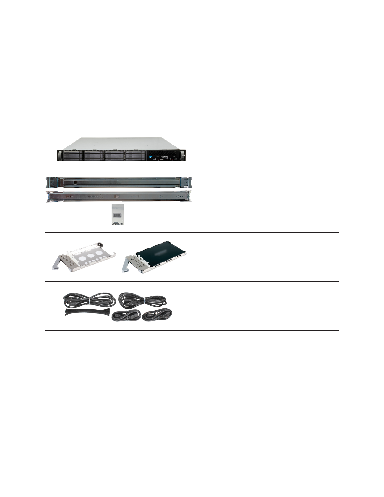
The R10 is a 1U All-Flash Storage Array with 16 SSD bays, redundant power supplies, and one TrueNAS controller.
16 SSD drive trays with up to 16 drives
installed
Accessory kit with 2 IEC C13 to NEMA 5-15P
power cords, 2 IEC C13 to C14 cords, and a
set of velcro cable ties
Set of rackmount rails and mounting hard-
ware
R10 All-Flash Storage Array
TrueNAS units are carefully packed and shipped with trusted carriers to arrive in perfect condition�
If there is any shipping damage or missing parts, please take photos and contact iXsystems support immediately at
support@ixsystems�com, 1-855-GREP4-iX (1-855-473-7449), or 1-408-943-4100�
Please locate and record the hardware serial numbers on the back of each chassis for quick reference�
Carefully unpack the shipping boxes and locate these components:
Page 3
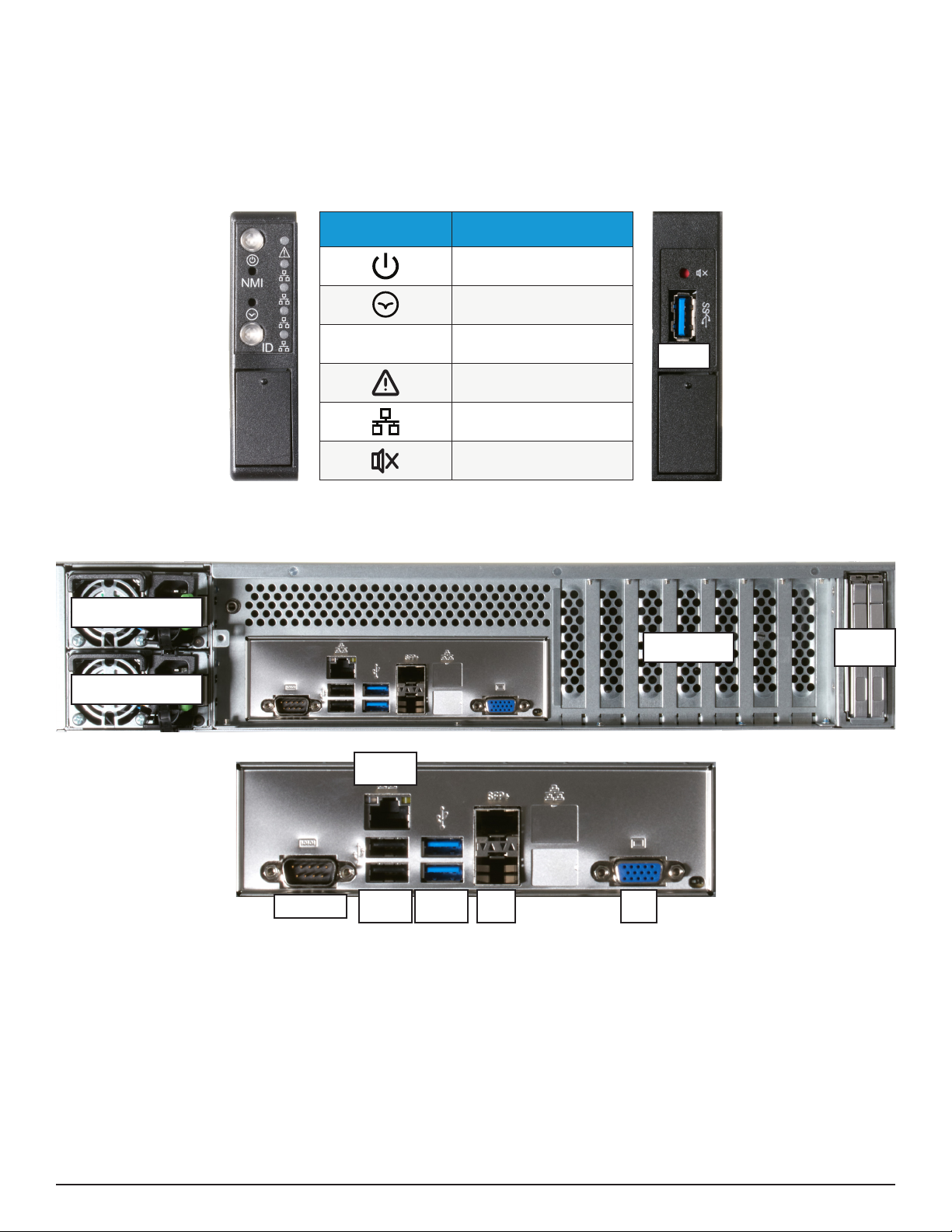
2.1 Front Ports and Indicators
Not pictured: Serial number and IPMI password stickers are on the back of the chassis underneath the USB ports.
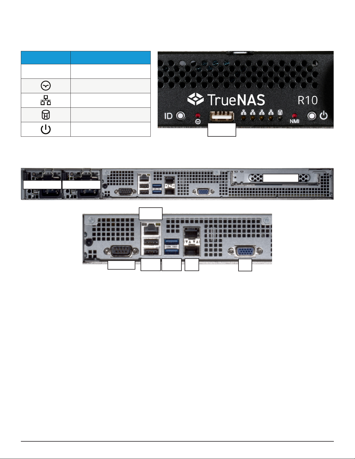
The back panel has redundant power supplies and various connection ports�
The R10 front panel has buttons for system ID and power, a USB 2.0 port, and lights for network and disk activity.
Light / Button Color and Indication
Blue: Locate ID Active
N/A: Reset Button
Amber: Link Active
Blue (Blinking): Disk Activity
Blue: System On
ID
USB 2.0
2.2 Rear Components and Ports
Power Supply 1 Power Supply 2
PCIe Expansion
OOBM
Ethernet
Serial Port
USB 2.0
x2
USB 3.0
x2
VGA
Port
SFP+
x2
Page 4
3 R20 Components
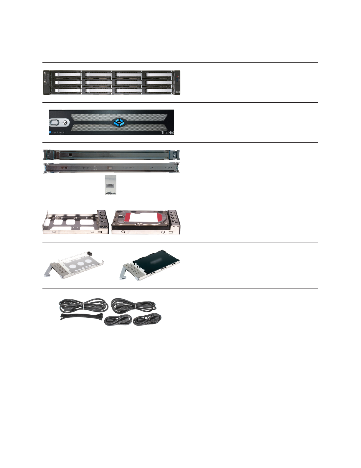
The R20 is a 2U Hybrid Storage Array that has 12 3.5” drive bays and 2 SSD drive bays, redundant power supplies,
and a single TrueNAS controller. You will nd these items when opening the R20 packaging:
2 SSD drive trays with up to 2 SSDs installed
12 3�5” drive trays with up to 12 hard drives
installed
Set of rackmount rails with mounting hard-
ware
R20 Hybrid Storage Array
Accessory kit with 2 IEC C13 to NEMA 5-15P
power cords, 2 IEC C13 to C14 cords, and a
set of velcro cable ties
Locking Bezel
Page 5
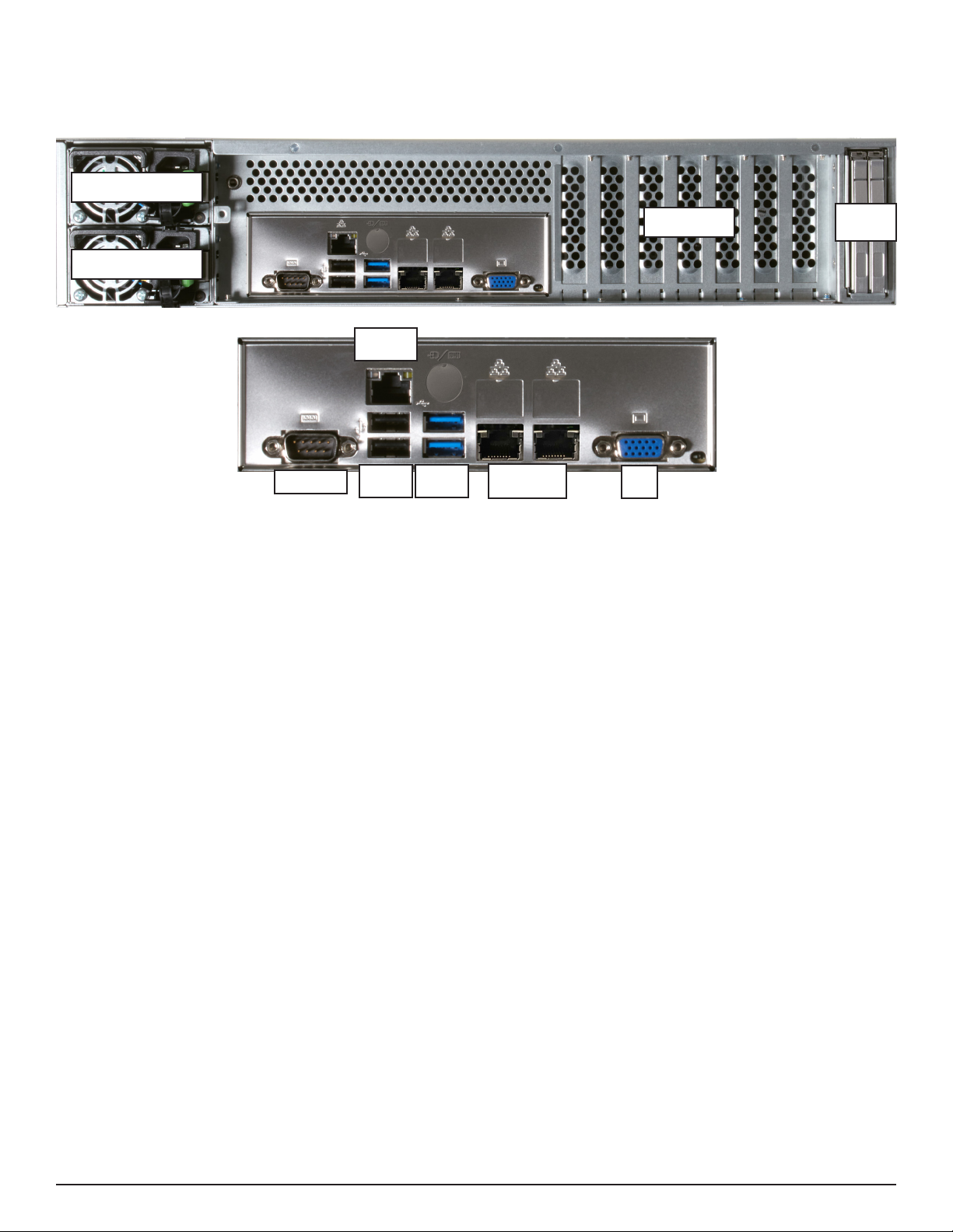
OOBM
Ethernet
Serial Port
USB 2.0
x2
USB 3.0
x2
VGA
Port
SFP+
x2
3.1 Front Ports and Indicators
The R20 front ears have button LEDs for power, system ID, and alarm mute� It also has lights for network activity
and faults, and a USB 3.0 port.
The fault indicator is on during the initial power-on self-test (POST) and turns o during normal operation. It turns
on if the TrueNAS software issues an alert�
Light / Button Color and Indication
Blue: System On
N/A: Reset Button
Blue: Locate ID Active
Green: Fault / Alert
Amber: Link Active
Red: Alarms Muted
ID
USB 3.0
The back panel has redundant power supplies, two SSD SATA Cache bays, and various connection ports�
Power Supply 2
Power Supply 1
PCIe Slots
SATA
Cache
3.2 Rear Components and Ports
Not pictured: Serial number and IPMI password stickers are on the back of the chassis underneath the USB ports.
Page 6
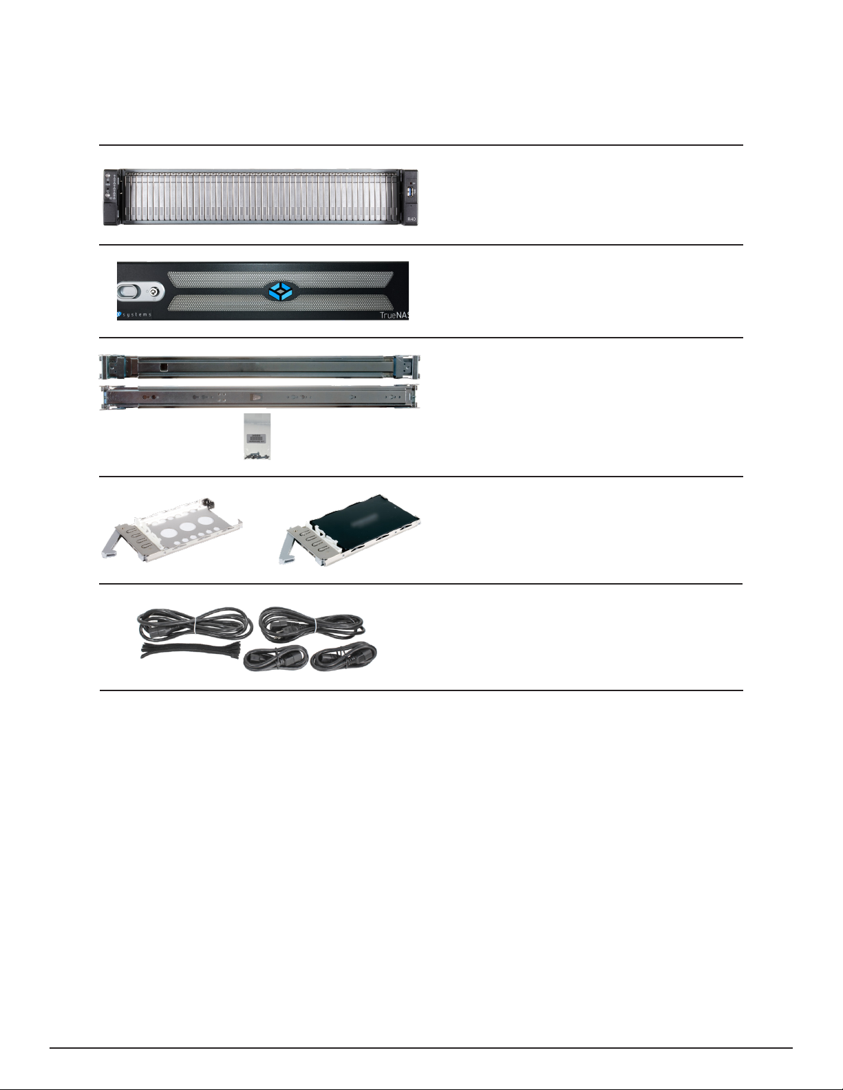
The back panel has redundant power supplies, two SSD SATA Cache bays, and various connection ports�
Power Supply 2
Power Supply 1
PCIe Slots
SATA
Cache
R20B Rear Components and Ports
Not pictured: Serial number and IPMI password stickers are on the back of the chassis underneath the USB ports.
OOBM
Ethernet
Serial Port
USB 2.0
x2
USB 3.0
x2
VGA
Port
10Gb RJ-45
x2
Page 7
4 R40 Components
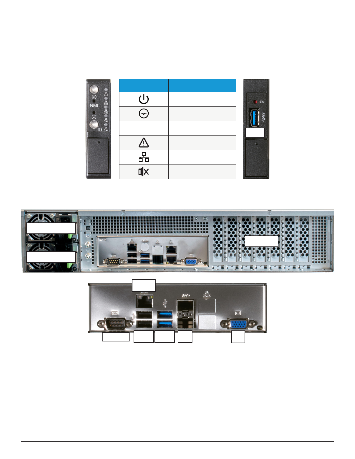
48 SSD drive trays with up to 48 drives
installed
The R40 is a 2U All-Flash Storage Array that has 48 SSD drive bays, redundant power supplies, and a single TrueNAS
controller. You will nd these items when opening the R40 packaging:
R40 All-Flash Storage Array
Set of rackmount rails with mounting
hardware
Accessory kit with 2 IEC C13 to NEMA
5-15P power cords, 2 IEC C13 to C14 cords,
and a set of velcro cable ties
Locking Bezel
Page 8
OOBM
Ethernet
Serial Port
USB 2.0
x2
USB 3.0
x2
VGA
Port
SFP+
x2
4.1 Front Ports and Indicators
The R40 front ears have button LEDs for power, system ID, and alarm mute� It also has lights for network activity
and faults, and a USB 3.0 port.
The fault indicator is on during the initial power-on self-test (POST) and turns o during normal operation. It turns
on if the TrueNAS software issues an alert�
Light / Button Color and Indication
Blue: System On
N/A: Reset Button
Blue: Locate ID Active
Green: Fault / Alert
Amber: Link Active
Red: Alarms Muted
ID
USB 3.0
The back panel has redundant power supplies and various connection ports�
Power Supply 2
Power Supply 1
PCIe Slots
4.2 Rear Components and Ports
Not pictured: Serial number and IPMI password stickers are on the back of the chassis underneath the USB ports.
Altri manuali per R Series
1
Questo manuale è adatto per i seguenti modelli
3
Indice
Altri manuali TrueNAS Magazzinaggio

TrueNAS
TrueNAS M Series Manuale utente

TrueNAS
TrueNAS X Series Manuale

TrueNAS
TrueNAS ES24F Manuale

TrueNAS
TrueNAS M Series Manuale utente

TrueNAS
TrueNAS Mini R Manuale

TrueNAS
TrueNAS R20A Manuale utente

TrueNAS
TrueNAS Mini X+ Manuale di installazione e funzionamento

TrueNAS
TrueNAS M Series Manuale

TrueNAS
TrueNAS X-Series Manuale

TrueNAS
TrueNAS ES60 Manuale


