
TTC Lifting CL05 Manuale utente

INSTRUCTUCTION
MANUAL
Note: Owner/Operator must read and understand
this instruction manual before using the clamp.

General
This manual contains important information for the
correct installation, operation, and maintenance of the
equipment described herein. The use of any clamp
presents some risk of personal injury or property damage.
All persons involved in such installation, operation and
maintenance should be thoroughly familiar with the
contents of this manual. To safeguard against the possibility
of property damage or personal injury follow the
recommendations and instructions of this manual and keep
it for further reference.
Aside from transporting plate, this clamp is well-suited to
turning over steel structures and welded constructions.
All plate clamps have been manufactured in accordance
with the Machinery Directive 98/37/EC.
They are type-tested 4 to 1 against breakage. Each unit
is proof-tested 1.5 times of the rated load.
Dot not use the clamps in areas containing flammable
vapors, liquids, gasses or combustible dust or fibres. Do not
use the clamp in highly corrosive, abrasive, wet
environments or in applications involving exposure to
temperatures below -40°C or above 80°C
Specification
1
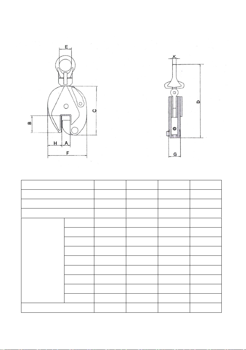
Model
CL05
CL10
CL20
CL30
Rated capacity t
0.5
1.0
2.0
3.0
Test load KN
7.35
14.7
29.4
44.1
Jaw Opening mm
0-15
0-20
0-25
0-30
Dimensions
mm
A
17
22
27
32
B
44
63
76
85
C
128
167
202
237
D
212
295
370
418
E
30
48
60
65
F
103
138
164
193
G
36
50
52
78
H
35
51
56
59
K
10
12
16
20
Net weight kg
1.9
4.5
7.5
14.8
2

Installation
3.1 Estimate the plate that is to be lifted or moved and
make sure it does not exceed the rated load of the clamp.
3.2 This clamp with pivoting shackle can be used for
lifting and transporting plate at various angles, but the load
capacity is reduced, as seen on the diagram below showing
the load/force capacities.
3.3 The pivoting shackle has the added advantage of
providing enough clamping farce to hold a plate safely, even
when transporting large-sized plates with the 2-legged lifting
system. Slipping or damage to the clamp is prevented.
When using two clamps to transporting large-sized
plates, pay attention to the reduced capacities of the
clamps.
3

The larger the angle of inclination on 2-leg slings the
greater is the tension force between the individual slings
and damps that has to be taken up in addition to the plate.
The reductions in carrying capacity for the inclinations 45"
and from 45~ to 60~ as shown as follows. Inclination angles
larger than 60~ are not permissible.
3.4 Make sure that the plate surface must have a
hardness below HRC 30/ Brinel1300.
3.5 Make a sure that the support to which the pivoting
shackled is attached is strong enough to hold several times
the weight of the plate.
4

4.Operation
Warning
To avoid damage and/or personal injury:
1 .Do not exceed maximum load of the clamp.
2. Do not use the clamp to lift or transport people.
3. Do not use damaged clamp or clamp that is not working
properly.
4. Do not lift or transport loads over people and make sure
all personnel remain clear of supported plate.
5. Do not lift the plate that is not fully engaged with the
clamping jaws.
6. Do not leave load supported by the clamp unattended
unless specific precaution have been taken.
7. Do not lift loads that are not balanced, and the holding
action is not secure. SAFETY WARNING
Never Exceed Maximum Capacity
Never Lift UNDER 20% Of The Rated
Capacity
Used on all hot rolled structural steel plates and
sections up to a surface hardness of 300 Brinell/32
Rockwell C
4.1 Attaching the plate
Turn the function lever clockwise to disengage the jaws.
Then put the plate to the end of the mouth of clamp. Move
the function lever counter- clockwise lo gripe and lock the
5

plate.
4.2 Danger zones
Do not lift or transport loads while personnel are in the
danger zone.
Do not stand or place hands or feet under the raised plate.
Raised loads are not to be left unattended for a longer
period of time.
The operator may only start to move the load when he is
sure the load will not overturn and that all personnel have
left the danger zone.
4.3 To loosen load
Move the function lever clockwise to disengage the jaws.
5. Maintenance/Inspection
To maintain continuous and satisfactory operation, a
regular inspection procedure must be initiated so that worn
or damaged parts can be replaced before they become
unsafe.
If faults are defected the clamp must be put out of service
immediately. The intervals of inspection must be determined
by the individual application and are based up on the type of
service to which the clamp is subjected.
The components of the clamp are to be inspected for
damage, wear, corrosion or other irregularities. Repairs may
only be carried out by a specialist workshop that uses
original spare parts.
6

6.Parts List
7

Item
Description
Quantity
1
Pivoting Shackle
1
2
Rollpin
1
3
Connecting Block
1
4
Body
1
5
Locknut
1
6
Lockwasher
1
7
Round Jaw
1
8
Screw
1
9
Rollpin
1
10
Function Lever
1
11
Connecting Block Pin
1
12
Pivoting Shackle Pin
1
13
Rollpin
1
14
Function Block
1
15
Pulling Spring
1
16
Rollpin
1
17
Connecting Plate
1
18
Clamping Jaw
1
19
Rollpin
1
20
Jaw Pin
1
21
Shim Washer
1
8
Questo manuale è adatto per i seguenti modelli
3
Indice
Manuali Paranco a catena popolari di altre marche

EINHELL
EINHELL Herkules H-F 1000 Manuale utente

RED ROOSTER
RED ROOSTER TCR-250 Manuale utente

POWERTEX
POWERTEX PCB-S1 Manuale utente

Parkside
Parkside PSZ 250 A1 Manuale utente

Ingersoll-Rand
Ingersoll-Rand QCH Series Manuale utente

Creative Conners
Creative Conners CM Varistar Smart Chain Hoist Manuale utente


