UNAVi ENB-X2 Manuale utente

CLASSFICATION.
Installation Manual
MODEL. ENB-X2
DOCUMENT NO.
BU No. 2
Hyundai Sonata In-Dash Navigation DIY Installation Guide
VERSION.
1.4
PAGE.
1
Information & Manual Copyright © 2013 UNAVI USA, Inc. All rights reserved. Date: 1/31/2013
Hyundai Sonata In-Dash Navigation
DIY Installation Guide
[Single CD Player Use Only]
MODEL: Hyundai Sonata 2012+
(Professional Use)
WWW.BUYUNAVI.COM
CLASSFICATION.
Installation Manual
MODEL. ENB-X2
DOCUMENT NO.
BU No. 2
Hyundai Sonata In-Dash Navigation DIY Installation Guide
VERSION.
1.4
PAGE.
2
Information & Manual Copyright © 2013 UNAVI USA, Inc. All rights reserved. Date: 1/31/2013
DISCLAIMER:
This ‘Do-It-Yourself Installation Guide’ is intended for informational and reference purposes only.
We do not recommend implicitly or explicitly, to anyone, performing any of the procedures
described in this guide. We are also not responsible for any property damage, personal injury
and/or death, or any other loss or damage that may result from following this informational guide.
Proceed with caution and care when performing modifications to your vehicle.
Be advised that making modification to your vehicle may void your manufacturer’s warranty.
Hyundai is a registered trademark of Hyundai Motor America. iPod is a registered trademark of Apple, Inc.
Kia is a registered trademark of Kia Motors America, Inc. Bluetooth is registered trademark of Bluetooth SIG, Inc.
Take care not to scratch the center fascia panel, dash trim, shift knob, etc.
Eject disc before removing the audio unit to prevent damaging the CD player’s load mechanism.
Disconnecting the negative (-) battery terminal is recommended prior to installation.
Do not touch the circuit board and the terminal connector of the flat cable with your bare hands.
Make sure all connectors and cables are plugged in properly.
All ground wires provided must be connected to chassis ground.
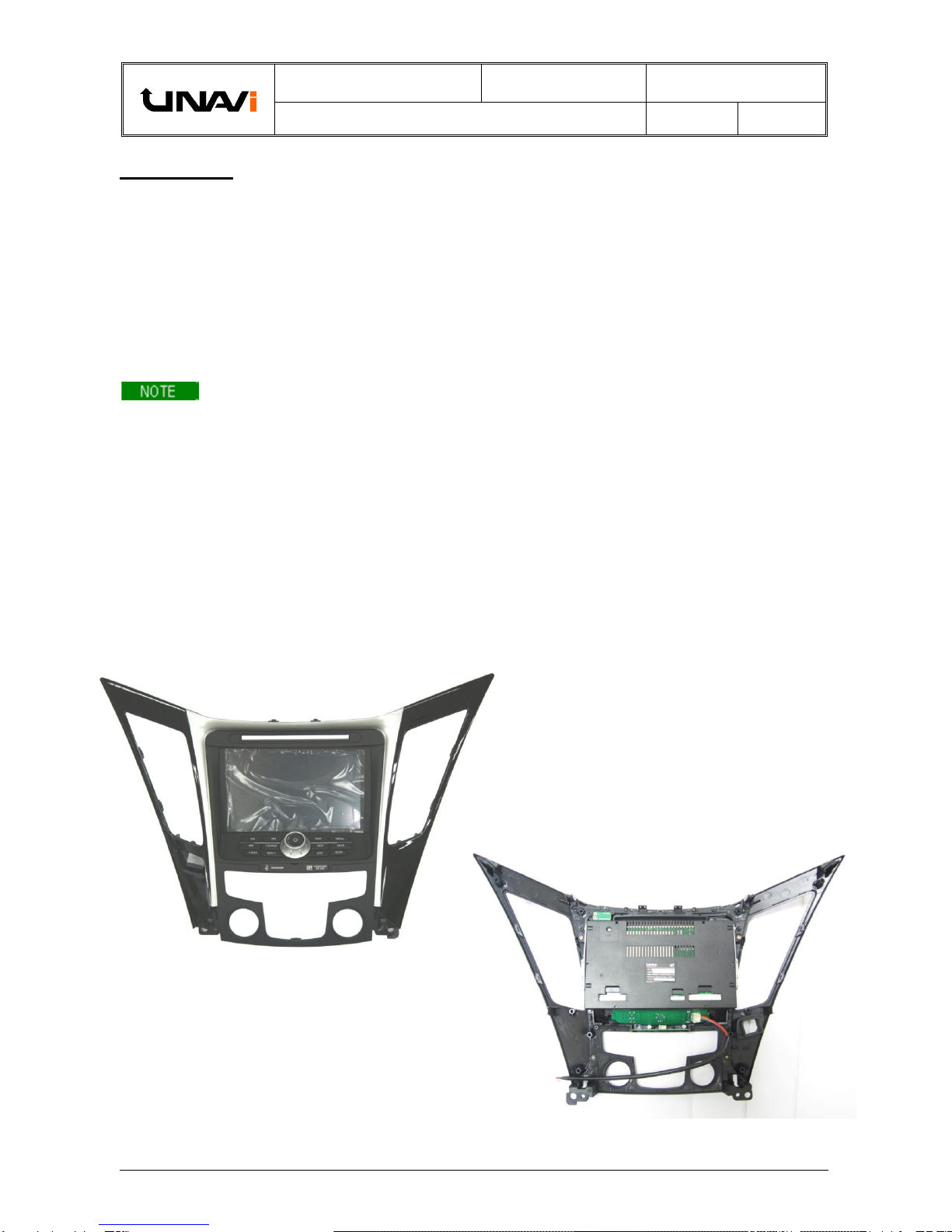
MAIN COMPONENTS:
(Not actual size, Items shown may vary)
Sonata fascia kit:
- Fascia
- Control keypad w/cable
- Bluetooth Antenna Port
- Main LCD Panel w/Mounting Bracket
- Passenger Airbag/Seat Belt Light PCB
Rear View
CLASSFICATION.
Installation Manual
MODEL. ENB-X2
DOCUMENT NO.
BU No. 2
Hyundai Sonata In-Dash Navigation DIY Installation Guide
VERSION.
1.4
PAGE.
3
Information & Manual Copyright © 2013 UNAVI USA, Inc. All rights reserved. Date: 1/31/2013
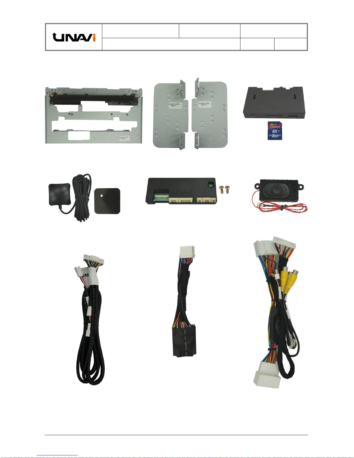
Front bracket replacement
Side mounting brackets (L & R)
Trip interface board + Screws
GPS antenna + Magnetic plate
Control box + SD Card
External speaker
Pass. Airbag/Seat Belt lamp cable
(Telltale Lamp)
SMART cable
SD + USB interface cables
(Continued)
CLASSFICATION.
Installation Manual
MODEL. ENB-X2
DOCUMENT NO.
BU No. 2
Hyundai Sonata In-Dash Navigation DIY Installation Guide
VERSION.
1.4
PAGE.
4
Information & Manual Copyright © 2013 UNAVI USA, Inc. All rights reserved. Date: 1/31/2013
TOOLS REQUIRED:
Masking Tape
Double-sided Tape *
Electrical Tape
Dash Trim Removal Tool *
Zip/Cable Ties
Scissor *
Plastic/Tin Snips *
Pliers *
Screwdriver (Torx Bit –T15, Phillips-head, Magnetized) *
Magnetic Screw & Bolt Tray
Power Drill
Unibit *
Electrical Connectors & Tools -
(Wire stripper, Crimper, T-Tap, etc.)
*Required Tools
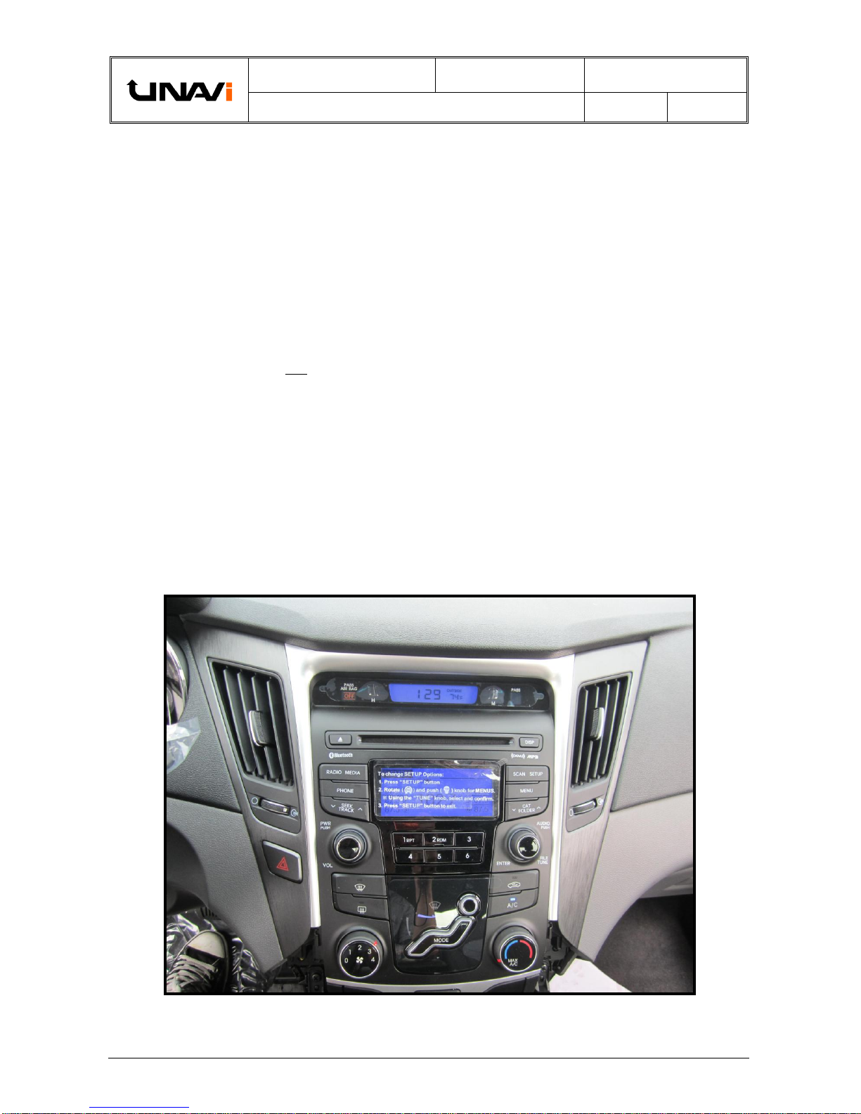
Pre-installation picture of non-navigation equipped model
(Trim levels may vary)

CLASSFICATION.
Installation Manual
MODEL. ENB-X2
DOCUMENT NO.
BU No. 2
Hyundai Sonata In-Dash Navigation DIY Installation Guide
VERSION.
1.4
PAGE.
5
Information & Manual Copyright © 2013 UNAVI USA, Inc. All rights reserved. Date: 1/31/2013
TPMS (TIRE PRESSURE MONITORING SYSTEM)
WARNING LAMP –ELECTROMAGNETIC INTERFERENCE
SYMPTOM/CONDITION
The TPMS malfunction indicator lamp may be illuminated if the vehicle is moving around electric power
supply cables or radio transmitters at police stations, government and public offices, broadcasting
stations, military installations, airports, transmitting towers, etc. External electronic devices connected
to the vehicle's power outlets (notebook computer, seat warmer, massager, coolers, GPS navigation,
mobile phone charger, etc.) may also cause this condition. The TPMS malfunction indicator lamp
generally turns off after the vehicle is removed from such interferences.
DIAGNOSIS:
If the TPMS indicator lamp is ON, and all four wheel sensors are checked and are working correctly,
external electronic devices connected to the vehicle's power outlets (notebook computer, seat warmer,
massager, coolers, etc.) may be the cause of this condition. Car manufacturers are aware that any
aftermarket device operating especially on the CAN-Bus system can trigger random warning lamps.
ACTION:
1. Please inspect if there are any other electronic devices inside the vehicle that may cause
electromagnetic interferences with the TPMS.
2. Drive the vehicle out of the strong electric field for about 5 minutes to verify that the condition is
corrected.
3. Relocate the Control Box and its related cables away from the TPMS sensor (typically located
behind the glove compartment).
4. If the above doesn’t work, use a metallic shield wrap or a similar material to wrap around the
Control Box and its cables with both ends of the shield connected to chassis ground at the point
of entry.
GPS ANTENNA INSTALLATION
The delay when the GPS receiver is first switched on is due to the latest ephemeris data being
downloaded, which is essential for the GPS receiver. The data is valid for around 4 hours and takes
approximately 20 seconds with a clear line of site to a satellite. It takes longer if using multiple satellites,
for instance if the GPS receiver is moving during first acquisition.
The antenna needs to be facing the sky through a non-metallic enclosure. A metallic enclosure
(including window tints) will prevent the RF signal being received by the antenna and cause a Faraday
cage effect. Likewise, positioning the antenna near to obstructions such as laptop screen or where
hands will be over the antenna should also be avoided, as the shielded will have a negative performance.
The GPSAntenna base is magnetic. On metal vehicles, position the antenna in the center of the
vehicle at the highest point.
For vehicles with non-metallic mounting surfaces, a metal plate with adhesive strips has been included
in the kit for easy mounting and installation. It is STRONGLY recommended to use this metal plate
underneath the antenna as it will improve signal acquisition.
Once the antenna has been positioned, route the antenna cable carefully to avoid damage.
Position the GPS antenna in the center of the vehicle at the highest point with a clear view of the sky.
CLASSFICATION.
Installation Manual
MODEL. ENB-X2
DOCUMENT NO.
BU No. 2
Hyundai Sonata In-Dash Navigation DIY Installation Guide
VERSION.
1.4
PAGE.
6
Information & Manual Copyright © 2013 UNAVI USA, Inc. All rights reserved. Date: 1/31/2013
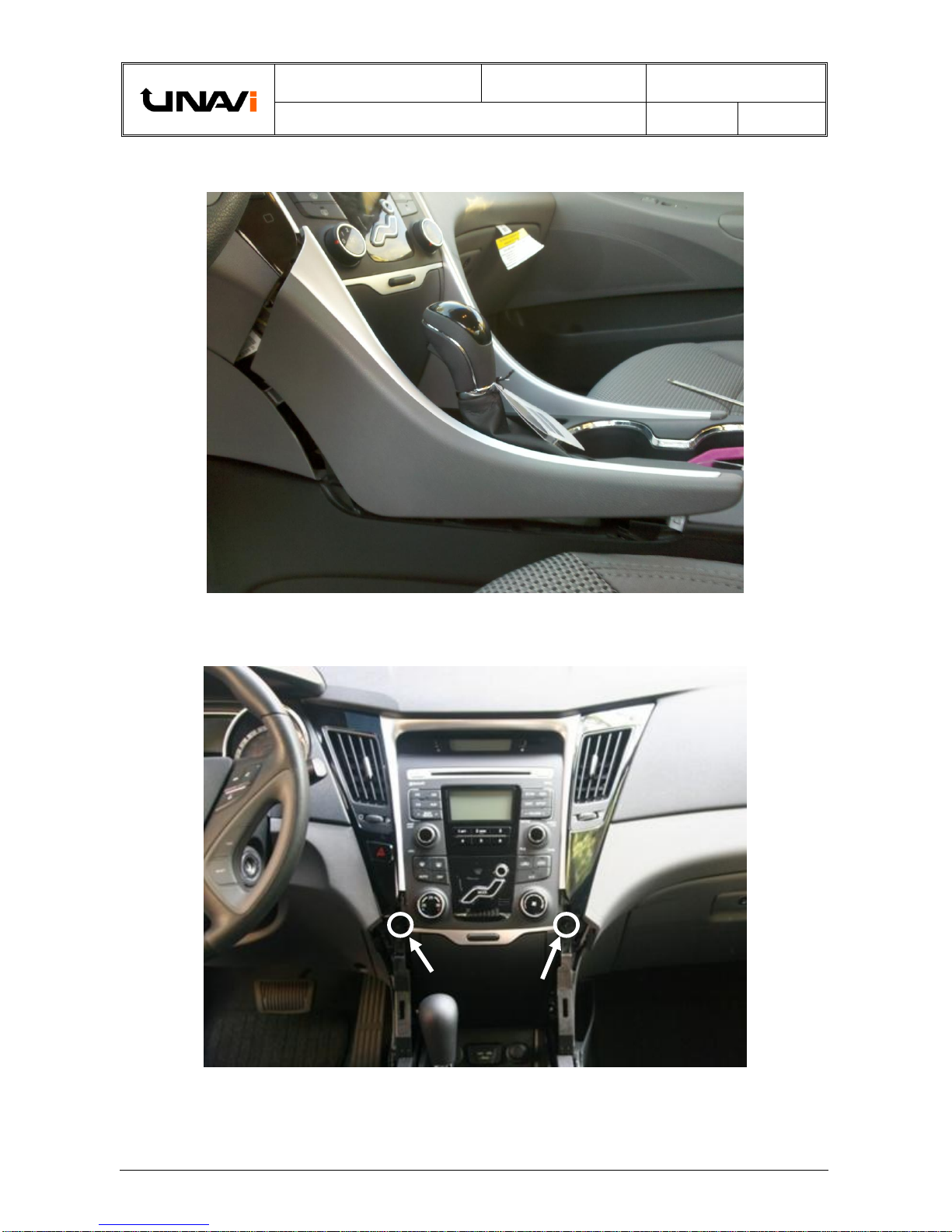
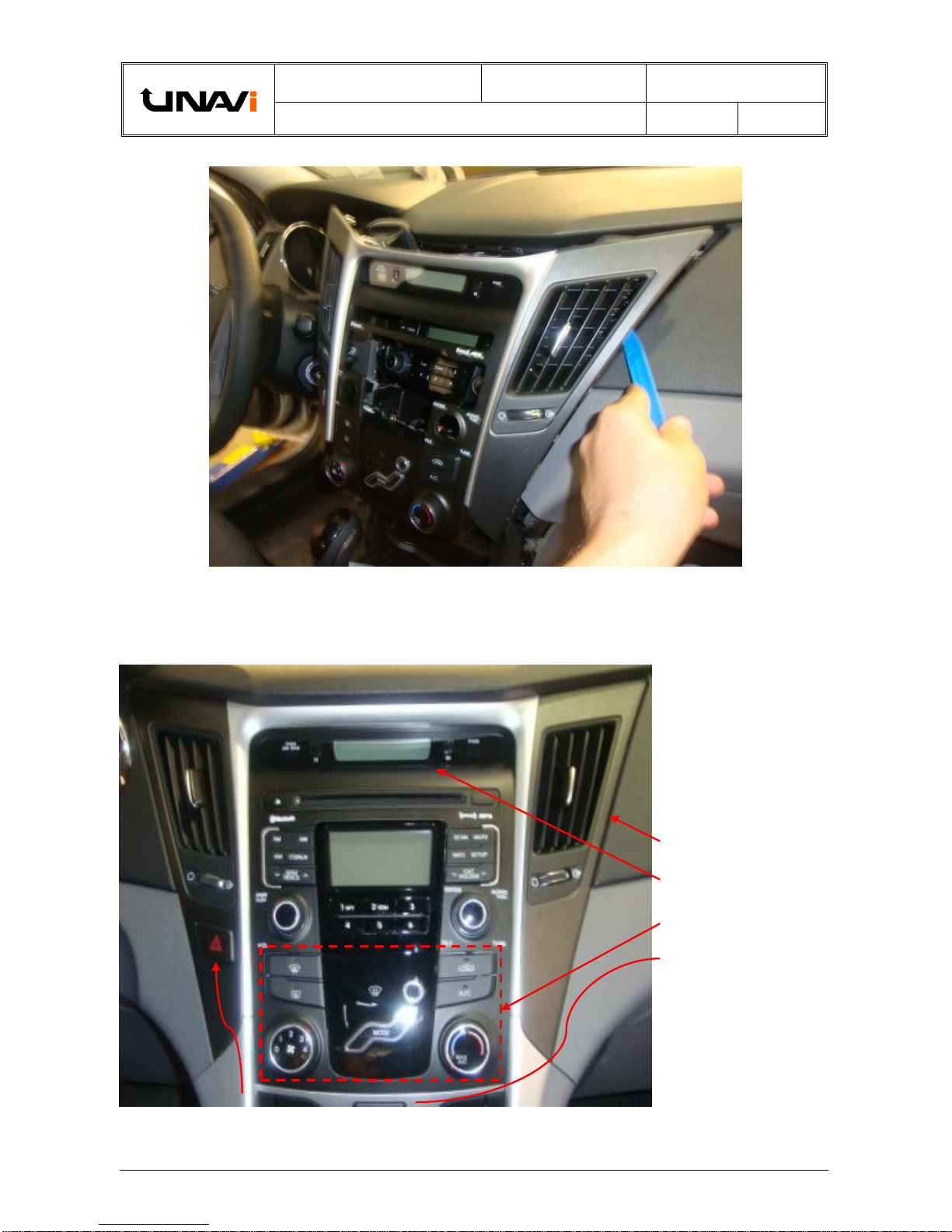
> INSTALLATION STARTS HERE <
Carefully remove the side crash pad garnish (L/R).
(Apply protective tapes and take care not to damage and scratch the interior dash and its related parts)
Loosen the two mounting screws securing the center fascia panel.
CLASSFICATION.
Installation Manual
MODEL. ENB-X2
DOCUMENT NO.
BU No. 2
Hyundai Sonata In-Dash Navigation DIY Installation Guide
VERSION.
1.4
PAGE.
7
Information & Manual Copyright © 2013 UNAVI USA, Inc. All rights reserved. Date: 1/31/2013
After the center fascia
panel has been removed,
disassemble the following
components from the
back and directly transfer
it to the new fascia kit:
Air vent assy. (L/R)
Clock display
Climate control
Emergency light switch
Plastic mounting clips
(not shown)
(Installation is the reverse
of removal)
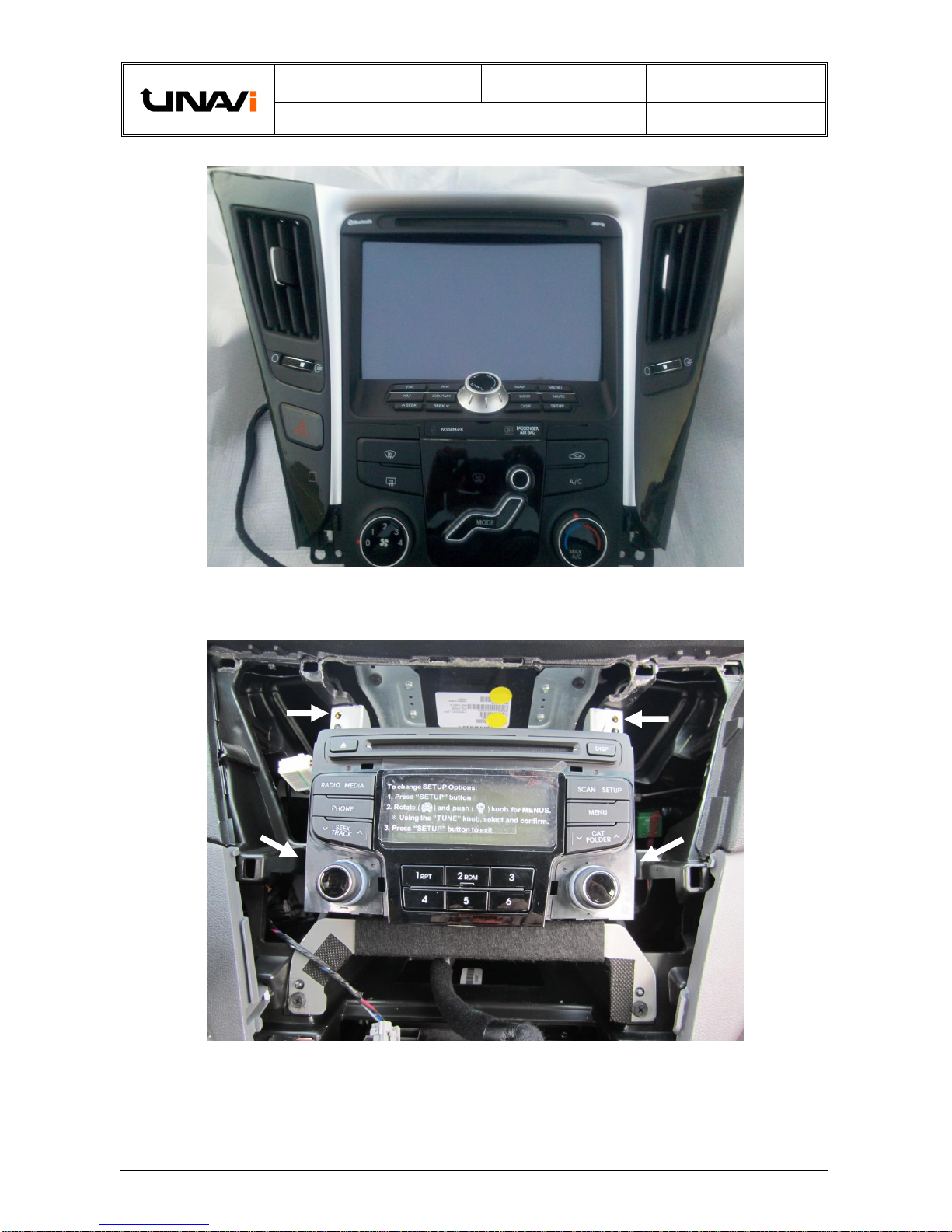
Gently pull out the center fascia panel and disconnect all connectors/hoses behind it.
(Installation is the reverse of removal)
CLASSFICATION.
Installation Manual
MODEL. ENB-X2
DOCUMENT NO.
BU No. 2
Hyundai Sonata In-Dash Navigation DIY Installation Guide
VERSION.
1.4
PAGE.
8
Information & Manual Copyright © 2013 UNAVI USA, Inc. All rights reserved. Date: 1/31/2013
Removed factory components transferred to the UNAVI fascia kit.
Remove the mounting screws (4EA) then pull out the audio head unit.
(Installation is the reverse of the removal)
CLASSFICATION.
Installation Manual
MODEL. ENB-X2
DOCUMENT NO.
BU No. 2
Hyundai Sonata In-Dash Navigation DIY Installation Guide
VERSION.
1.4
PAGE.
9
Information & Manual Copyright © 2013 UNAVI USA, Inc. All rights reserved. Date: 1/31/2013
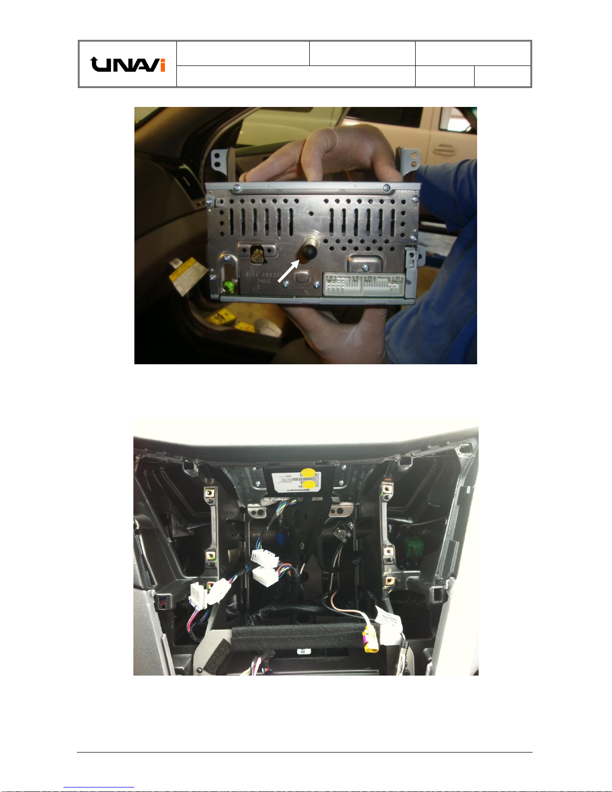
Rear view of the audio head unit after removing connectors and cables.
Remove the rear frame stabilizer.
Image of center fascia panel and audio head unit removed.
CLASSFICATION.
Installation Manual
MODEL. ENB-X2
DOCUMENT NO.
BU No. 2
Hyundai Sonata In-Dash Navigation DIY Installation Guide
VERSION.
1.4
PAGE.
10
Information & Manual Copyright © 2013 UNAVI USA, Inc. All rights reserved. Date: 1/31/2013
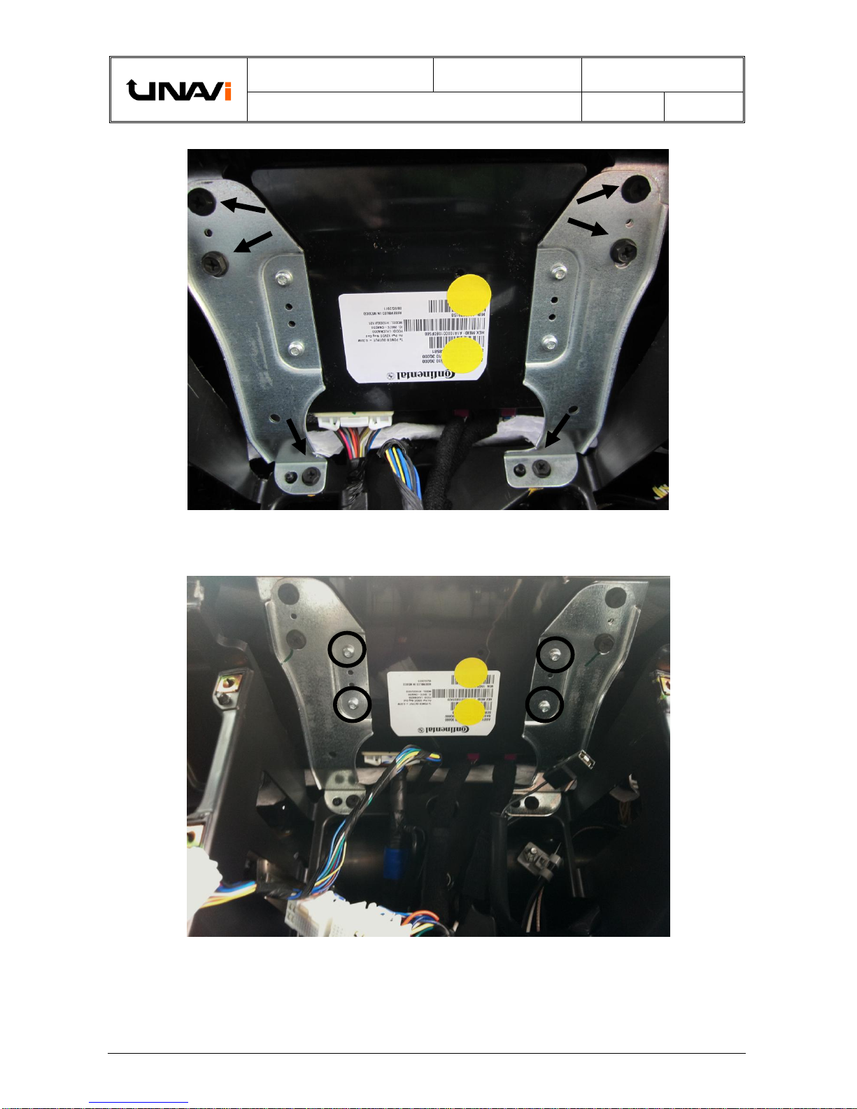
Remove the screws (6EA) securing the BlueLink modem as shown.
After the modem is disassembled from the dash panel, use a Torx driver (T15 bit)
to remove the silver mounting bracket screws (4EA) off of the BlueLink modem.
Altri manuali per ENB-X2
5
Indice
Altri manuali UNAVi Sistema di navigazione per auto

UNAVi
UNAVi ENB-X2 Manuale utente

UNAVi
UNAVi ENB-X2 Manuale utente

UNAVi
UNAVi ENB-X1 Manuale utente

UNAVi
UNAVi X5 Manuale utente

UNAVi
UNAVi X5 Istruzioni per il montaggio

UNAVi
UNAVi ENB-X2 Manuale utente

UNAVi
UNAVi ENB-X2 Manuale utente

UNAVi
UNAVi Kia Optima 2011+ Manuale utente

UNAVi
UNAVi ENB-X2 Manuale utente


