Table of contents
I
Table of Contents
1. Block circuits ......................................................................................................................................1
1.1. Block circuit baseboard (CPU & network)....................................................................................1
1.2. Block circuit option board.............................................................................................................2
1.3. Wiring diagram .............................................................................................................................3
2. Electronics ..........................................................................................................................................4
2.1. Check-points ................................................................................................................................4
2.1.1. Voltage supply baseboard.................................................................................................4
2.1.2. Voltage supply option board .............................................................................................4
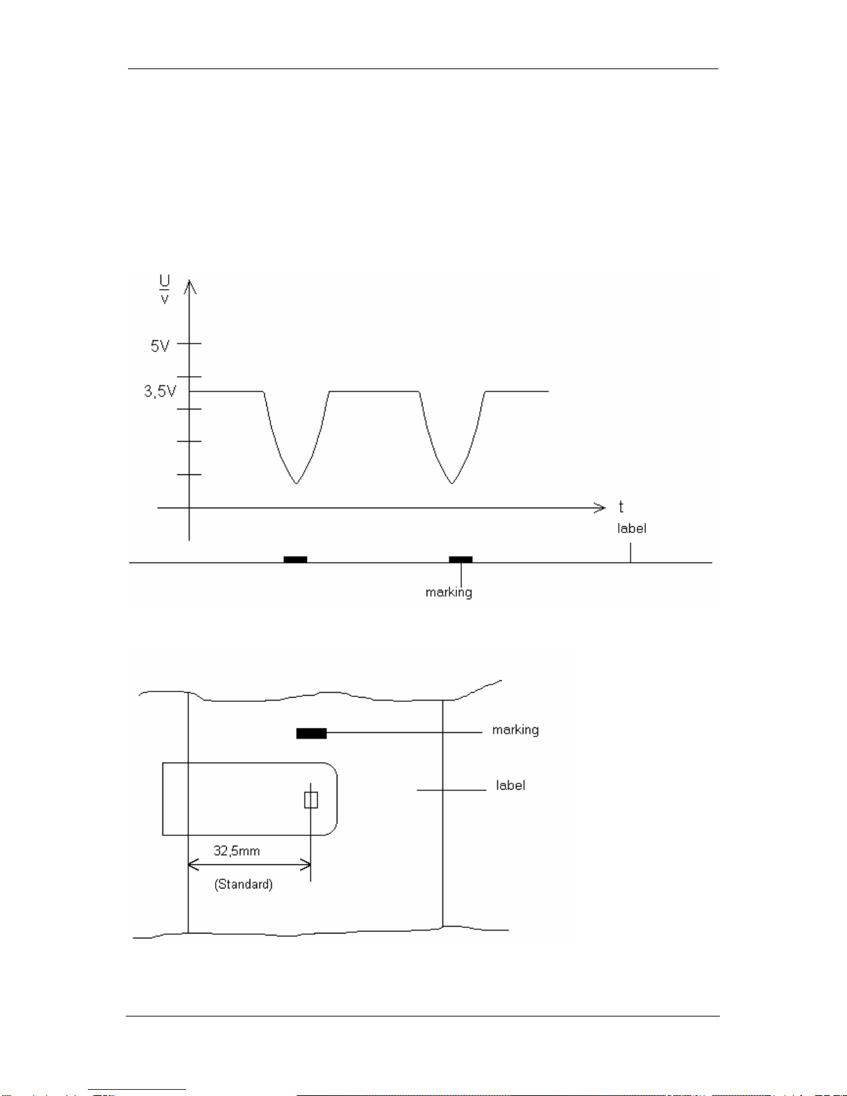
2.1.3. Photocells..........................................................................................................................5
2.1.4. Clock-signals.....................................................................................................................8
2.1.5. Strobe-signals...................................................................................................................9
2.1.6. Motor signals...................................................................................................................12
2.1.7. External control inputs / outputs (option board)..............................................................12
2.2. Component parts of baseboard..................................................................................................13
2.3. Component parts of option board...............................................................................................14
2.4. Changing of fuses ......................................................................................................................15
2.4.1. Primary fuse....................................................................................................................15
2.4.2. Secondary fuse...............................................................................................................15
2.5. Service monitor ..........................................................................................................................16
2.5.1. Valuation of label parameters .........................................................................................16
2.5.2. Error message: label error ..............................................................................................17
2.5.3. Error elimination..............................................................................................................18
2.5.4. Monitor ............................................................................................................................18
3. Mechanics .........................................................................................................................................19
3.1. Exchange of print head ..............................................................................................................19
3.2. Adjustment of print head ............................................................................................................20
3.2.1. Pressure..........................................................................................................................20
3.2.2. Print quality .....................................................................................................................20
3.3. Cleaning of print head................................................................................................................21
3.4. Exchange of pressure roll...........................................................................................................22
3.5. Exchange of ribbon unwinding roll .............................................................................................23
3.6. To oil and lubricate.....................................................................................................................24
3.7. Option dispenser ........................................................................................................................25
3.7.1. Exchange dispenser........................................................................................................25
3.8. Option cutter...............................................................................................................................26
3.8.1. Cleaning/ servicing/changing of cutter............................................................................26
3.9. Options winder PR 25 / PR 26 ...................................................................................................27
3.9.1. Exchange motor..............................................................................................................27
3.10. Option memory-card.................................................................................................................28
3.10.1. Mounting of MC plug-in unit..........................................................................................28
4. Possible sources of error ................................................................................................................29
4.1. Error messages on the display...................................................................................................29
4.2. General errors ............................................................................................................................32