
Vega VEGABAR 81 Manuale utente

Operating Instructions
Pressure transmitter with chemical seal
VEGABAR 81
Foundation Fieldbus
Document ID: 45021

2
Contents
VEGABAR 81 • Foundation Fieldbus
45021-EN-200529
Contents
1 About this document ............................................................................................................... 4
1.1 Function ........................................................................................................................... 4
1.2 Target group ..................................................................................................................... 4
1.3 Symbols used................................................................................................................... 4
2 For your safety ......................................................................................................................... 5
2.1 Authorised personnel ....................................................................................................... 5
2.2 Appropriate use................................................................................................................ 5
2.3 Warning about incorrect use............................................................................................. 5
2.4 General safety instructions............................................................................................... 5
2.5 EU conformity................................................................................................................... 5
2.6 NAMUR recommendations .............................................................................................. 6
2.7 Installation and operation in the USA and Canada ........................................................... 6
2.8 Environmental instructions ............................................................................................... 6
3 Product description ................................................................................................................. 7
3.1 Conguration.................................................................................................................... 7
3.2 Principle of operation........................................................................................................ 8
3.3 Packaging, transport and storage................................................................................... 11
3.4 Accessories.................................................................................................................... 11
4 Mounting................................................................................................................................. 13
4.1 General instructions ....................................................................................................... 13
4.2 Instructions for oxygen applications ............................................................................... 15
4.3 Ventilation and pressure compensation.......................................................................... 15
4.4 Process pressure measurement..................................................................................... 17
4.5 Level measurement........................................................................................................ 19
4.6 External housing ............................................................................................................ 20
5 Connecting to the bus system.............................................................................................. 21
5.1 Preparing the connection ............................................................................................... 21
5.2 Connecting..................................................................................................................... 22
5.3 Single chamber housing................................................................................................. 23
5.4 Double chamber housing ............................................................................................... 23
5.5 Double chamber housing with VEGADIS-Adapter.......................................................... 25
5.6 Housing IP66/IP68 (1 bar) .............................................................................................. 26
5.7 External housing with version IP68 (25 bar) ................................................................... 26
5.8 Switch-on phase............................................................................................................. 28
6 Set up with the display and adjustment module ................................................................ 29
6.1 Insert display and adjustment module............................................................................ 29
6.2 Adjustment system......................................................................................................... 30
6.3 Measured value indication.............................................................................................. 31
6.4 Parameter adjustment - Quick setup .............................................................................. 32
6.5 Parameter adjustment - Extended adjustment................................................................ 32
6.6 Saving the parameterisation data................................................................................... 44
7 Setup with PACTware............................................................................................................. 45
7.1 Connect the PC.............................................................................................................. 45
7.2 Parameter adjustment with PACTware............................................................................ 45
7.3 Saving the parameterisation data................................................................................... 46

3
Contents
VEGABAR 81 • Foundation Fieldbus
45021-EN-200529
8 Set up with other systems .................................................................................................... 47
8.1 DD adjustment programs ............................................................................................... 47
9 Diagnosis, asset management and service ........................................................................ 48
9.1 Maintenance .................................................................................................................. 48
9.2 Diagnosis memory ......................................................................................................... 48
9.3 Asset Management function........................................................................................... 49
9.4 Rectify faults................................................................................................................... 52
9.5 Exchanging the electronics module................................................................................ 52
9.6 Exchange process module on version IP68 (25 bar) ...................................................... 52
9.7 Software update ............................................................................................................. 53
9.8 How to proceed if a repair is necessary.......................................................................... 54
10 Dismount................................................................................................................................. 55
10.1 Dismounting steps.......................................................................................................... 55
10.2 Disposal ......................................................................................................................... 55
11 Supplement ............................................................................................................................ 56
11.1 Technical data ................................................................................................................ 56
11.2 Chemical seal with vacuum applications........................................................................ 65
11.3 Device communication Foundation Fieldbus.................................................................. 69
11.4 Dimensions .................................................................................................................... 70
11.5 Industrial property rights................................................................................................. 79
11.6 Trademark ...................................................................................................................... 79
Safety instructions for Ex areas
TakenoteoftheExspecicsafetyinstructionsforExapplications.
These instructions are attached as documents to each instrument
with Ex approval and are part of the operating instructions.
Editing status: 2020-05-12

4
1 About this document
VEGABAR 81 • Foundation Fieldbus
45021-EN-200529
1 About this document
1.1 Function
This instruction provides all the information you need for mounting,
connection and setup as well as important instructions for mainte-
nance,faultrectication,theexchangeofpartsandthesafetyofthe
user. Please read this information before putting the instrument into
operation and keep this manual accessible in the immediate vicinity
of the device.
1.2 Target group
This operating instructions manual is directed to trained personnel.
Thecontentsofthismanualmustbemadeavailabletothequalied
personnel and implemented.
1.3 Symbols used
Document ID
This symbol on the front page of this instruction refers to the Docu-
ment ID. By entering the Document ID on www.vega.com you will
reach the document download.
Information, note, tip: This symbol indicates helpful additional infor-
mation and tips for successful work.
Note: This symbol indicates notes to prevent failures, malfunctions,
damage to devices or plants.
Caution: Non-observance of the information marked with this symbol
may result in personal injury.
Warning: Non-observance of the information marked with this symbol
may result in serious or fatal personal injury.
Danger: Non-observance of the information marked with this symbol
results in serious or fatal personal injury.
Ex applications
This symbol indicates special instructions for Ex applications.
• List
The dot set in front indicates a list with no implied sequence.
1 Sequence of actions
Numbers set in front indicate successive steps in a procedure.
Battery disposal
This symbol indicates special information about the disposal of bat-
teries and accumulators.

5
2 For your safety
VEGABAR 81 • Foundation Fieldbus
45021-EN-200529
2 For your safety
2.1 Authorised personnel
All operations described in this documentation must be carried out
onlybytrained,qualiedpersonnelauthorisedbytheplantoperator.
During work on and with the device, the required personal protective
equipment must always be worn.
2.2 Appropriate use
The VEGABAR 81 is a pressure transmitter for process pressure and
hydrostatic level measurement.
Youcannddetailedinformationabouttheareaofapplicationin
chapter "Product description".
Operational reliability is ensured only if the instrument is properly
usedaccordingtothespecicationsintheoperatinginstructions
manual as well as possible supplementary instructions.
2.3 Warning about incorrect use
Inappropriate or incorrect use of this product can give rise to applica-
tion-specichazards,e.g.vesseloverllthroughincorrectmounting
or adjustment. Damage to property and persons or environmental
contamination can result. Also, the protective characteristics of the
instrument can be impaired.
2.4 General safety instructions
This is a state-of-the-art instrument complying with all prevailing
regulations and directives.The instrument must only be operated in a
technicallyawlessandreliablecondition.Theoperatorisresponsi-
ble for the trouble-free operation of the instrument. When measuring
aggressive or corrosive media that can cause a dangerous situation
if the instrument malfunctions, the operator has to implement suitable
measures to make sure the instrument is functioning properly.
The safety instructions in this operating instructions manual, the na-
tional installation standards as well as the valid safety regulations and
accident prevention rules must be observed by the user.
For safety and warranty reasons, any invasive work on the device
beyond that described in the operating instructions manual may be
carried out only by personnel authorised by the manufacturer. Arbi-
traryconversionsormodicationsareexplicitlyforbidden.Forsafety
reasons,onlytheaccessoryspeciedbythemanufacturermustbe
used.
To avoid any danger, the safety approval markings and safety tips on
the device must also be observed.
2.5 EU conformity
ThedevicefullsthelegalrequirementsoftheapplicableEUdirec-
tives.ByaxingtheCEmarking,weconrmtheconformityofthe
instrument with these directives.

6
2 For your safety
VEGABAR 81 • Foundation Fieldbus
45021-EN-200529
The EU conformity declaration can be found on our homepage.
Duetothedesignofitsprocessttings,thedevicedoesnotsubject
of EU pressure device directive if it is operated at process pressures
≤200bar.1)
2.6 NAMUR recommendations
NAMUR is the automation technology user association in the process
industry in Germany. The published NAMUR recommendations are
acceptedasthestandardineldinstrumentation.
ThedevicefullstherequirementsofthefollowingNAMURrecom-
mendations:
• NE 21 – Electromagnetic compatibility of equipment
• NE53–Compatibilityofelddevicesanddisplay/adjustment
components
• NE107–Self-monitoringanddiagnosisofelddevices
For further information see www.namur.de.
2.7 Installation and operation in the USA and
Canada
This information is only valid for USA and Canada. Hence the follow-
ing text is only available in the English language.
Installations in the US shall comply with the relevant requirements of
the National Electrical Code (ANSI/NFPA 70).
Installations in Canada shall comply with the relevant requirements of
the Canadian Electrical Code.
2.8 Environmental instructions
Protection of the environment is one of our most important duties.
That is why we have introduced an environment management system
with the goal of continuously improving company environmental pro-
tection.Theenvironmentmanagementsystemiscertiedaccording
to DIN EN ISO 14001.
Pleasehelpusfullthisobligationbyobservingtheenvironmental
instructions in this manual:
• Chapter "Packaging, transport and storage"
• Chapter "Disposal"
1) Exception:Versions with measuring ranges from 250 bar. These are subject
of the EU Pressure Device Directive.

7
3 Product description
VEGABAR 81 • Foundation Fieldbus
45021-EN-200529
3 Product description
3.1 Conguration
The scope of delivery encompasses:
• VEGABAR 81 pressure transmitter
The further scope of delivery encompasses:
• Documentation
– Quick setup guide VEGABAR 81
– Testcerticateforpressuretransmitters
– Instructions for optional instrument features
– Ex-specic"Safety instructions" (with Ex versions)
– Ifnecessary,furthercerticates
Information:
Optional instrument features are also described in this operating
instructions manual.The respective scope of delivery results from the
orderspecication.
This operating instructions manual applies to the following instrument
versions:
• Hardware from 1.0.0
• Software version from 1.2.0
Note:
Youcanndthehardwareandsoftwareversionoftheinstrumentas
follows:
• On the type plate of the electronics module
• In the adjustment menu under "Info"
Thetypelabelcontainsthemostimportantdataforidenticationand
use of the instrument:
7
6
4
5
2
3
1
Fig. 1: Layout of the type label (example)
1 Product code
2 Field for approvals
3 Technical data
4 Serial number of the instrument
5 QR code
6 Symbol of the device protection class
7 ID numbers, instrument documentation
Scope of delivery
Scope of this operating
instructions
Type label

8
3 Product description
VEGABAR 81 • Foundation Fieldbus
45021-EN-200529
The type label contains the serial number of the instrument. With it
youcanndthefollowinginstrumentdataonourhomepage:
• Product code (HTML)
• Delivery date (HTML)
• Order-specicinstrumentfeatures(HTML)
• Operating instructions and quick setup guide at the time of ship-
ment (PDF)
• Order-specicsensordataforanelectronicsexchange(XML)
• Testcerticate(PDF)-optional
Move to "www.vega.com"andenterinthesearcheldtheserial
number of your instrument.
Alternatively, you can access the data via your smartphone:
• Download the VEGA Tools app from the "Apple App Store" or the
"Google Play Store"
• Scan the DataMatrix code on the type label of the instrument or
• Enter the serial number manually in the app
3.2 Principle of operation
VEGABAR 81 is suitable for applications in virtually all industries. It is
used for the measurement of the following pressure types.
• Gauge pressure
• Absolute pressure
• Vacuum
Measured products are gases, vapours and liquids.
The chemical seal systems of VEGABAR 81, which are optimally
adapted to the process, also allow measurement of highly corrosive
and hot products.
The VEGABAR 81 is suitable for the measurement of the following
process variables:
• Process pressure
• Level
Fig. 2: Process pressure measurement VEGABAR 81
Serial number - Instru-
ment search
Application area
Measured products
Measured variables

9
3 Product description
VEGABAR 81 • Foundation Fieldbus
45021-EN-200529
Depending on the version, the VEGABAR 81 is also suitable for
electronicdierentialpressuremeasurement.Forthis,theinstrument
is combined with a slave sensor.
Fig. 3: Electronic dierential pressure measurement through Master/Slave
combination
Youcannddetailedinformationintheoperatinginstructionsofthe
respective slave sensor.
The VEGABAR 81 is equipped with a chemical seal. It consists of a
stainless steel diaphragm and a transmission liquid.
A chemical seal has two tasks:
• Separation of the sensor element from the medium
• Transmission of the process pressure to the sensor element
1
2
3
4
Fig. 4: Conguration of a chemical seal
1 Sensor element
2 Sealed screw
3 Transmission liquid
4 Stainless steel diaphragm
Electronicdierential
pressure
Chemical seal
10
3 Product description
VEGABAR 81 • Foundation Fieldbus
45021-EN-200529
Thechemicalsealisavailableindierentversions,seechapter
"Dimensions".
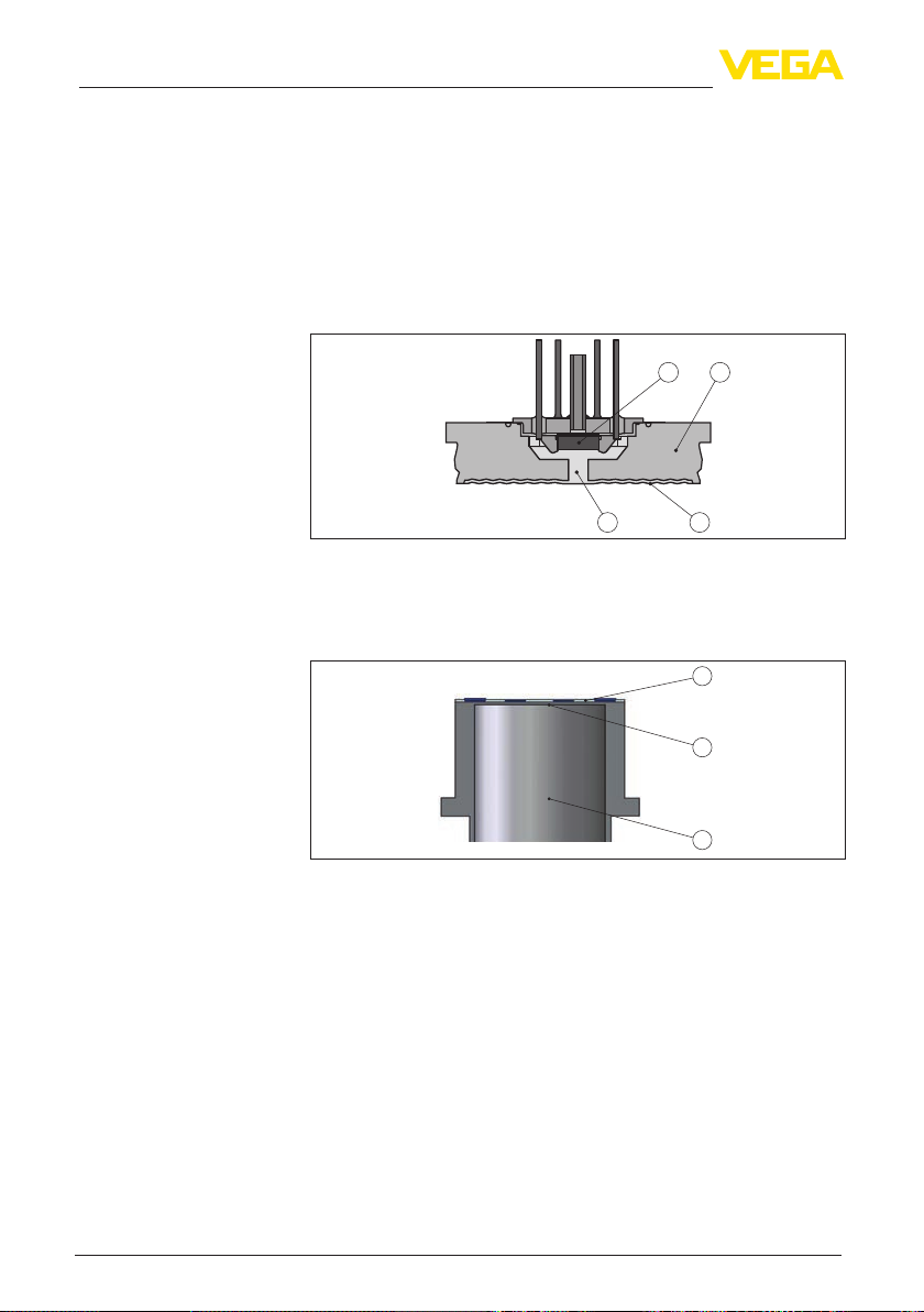
The process pressure acts on the sensor element via the isolat-
ing diaphragm.The process pressure causes a resistance change
which is converted into a corresponding output signal and output as
measured value.
Measuringrangesupto40bar:piezoresistivesensorelementwith
a transmission liquid, measuring ranges from 100 bar: a dry strain
gauge (DMS) sensor element.
1
3 4
2
Fig. 5: Conguration of a measuring system with piezoresistive sensor element
1 Sensor element
2 Base element
3 Transmission liquid
4 Diaphragm
1
2
3
Fig. 6: Conguration of a measuring system with strain gauge (DMS) sensor
element
1 Sensor element
2 Process diaphragm
3 Pressure cylinder
Relative pressure: the measuring cell is open to the atmosphere.
The ambient pressure is detected in the measuring cell and compen-
sated.Itthushasnoinuenceonthemeasuredvalue.
Absolute pressure: the measuring cell contains vacuum and is
encapsulated.The ambient pressure is not compensated and does
henceinuencethemeasuredvalue.
The measuring system is completely welded and thus sealed against
the process.
Measuring system
Pressure types
Seal concept
Altri manuali per VEGABAR 81
16
Indice
Altri manuali Vega Trasmettitore

Vega
Vega VEGADIF 65 Manuale utente

Vega
Vega VEGABAR 86 Manuale utente

Vega
Vega VEGABAR 87 Manuale utente

Vega
Vega VEGABAR 87 Manuale utente

Vega
Vega VEGABAR 51 Manuale utente

Vega
Vega VEGABAR 54 Manuale utente

Vega
Vega VEGABAR 55 Manuale utente

Vega
Vega VEGAWELL 52 Manuale utente

Vega
Vega VEGADIF 85 Manuale utente

Vega
Vega VEGABAR 53 Manuale utente

Vega
Vega VEGABAR 81 Manuale utente

Vega
Vega VEGABAR 87 Manuale utente

Vega
Vega RMT-10 Manuale utente

Vega
Vega VEGABAR 82 Manuale utente

Vega
Vega VEGABAR 82 Manuale utente

Vega
Vega VEGABAR 81 Manuale utente

Vega
Vega VEGABAR S 16 Manuale utente

Vega
Vega VEGABAR 52 Manuale utente

Vega
Vega VEGABAR 82 Manuale utente

Vega
Vega VEGABAR 87 Manuale utente


