VIAIR 425C Manuale utente


IMPORTANT SAFETY INSTRUCTIONS
CAUTION - To reduce risk of electrical shock:
- Donotdisassemble.Donotattemptrepairsormodications.Refertoqualiedserviceagencies
forallserviceandrepairs.
- Donotusethisproductinanareawhereitcanfallorbepulledintowaterorotherliquids.
- Donotreachforthisproductifithasfallenintoliquid.
- Usethiscompressorwith12-voltDCsystemsonly.
- Thisproductshouldneverbeleftunattendedduringuse.
WARNING - To prevent injury:
- Neverallowchildrentooperatethiscompressor.Closesupervisionisnecessarywhenthiscompressor
isbeingusednearchildren.
- ThiscompressorwillbecomeveryHOTduringandimmediatelyafteruse.Donottouchanypartofthis
compressorwithbarehandsduringandimmediatelyafteruse.
- Donotusethisproductnearamesorexplosivematerialsorwhereaerosolproductsarebeingused.
- Donotoperatethisproductwhereoxygenisbeingadministered.
- Donotpumpanythingotherthanatmosphericair.
- Neverusethisproductwhilesleepyordrowsy.
- Donotuseanytoolsorattachmentswithoutrstdeterminingmaximumairpressureforthattool
or attachment.
- Neverpointanyairnozzleorairsprayertowardanotherpersonoranypartofthebody.
- ThisaircompressorisequippedwithanAutomaticResetThermalProtector,andcanautomatically
restartafterthethermalprotectorresets.Alwayscutoffpowersourcewhenthermalprotector
becomesactivated.
- Wearsafetyglassesorgoggleswhenoperatingthisproduct.
- Useonlyinwellventilatedareas.
INSTALLATION
Pleasereadandfollowtheinstallationinstructionscarefullytoavoidinjuryordamagetothe
compressorandyourvehicle.
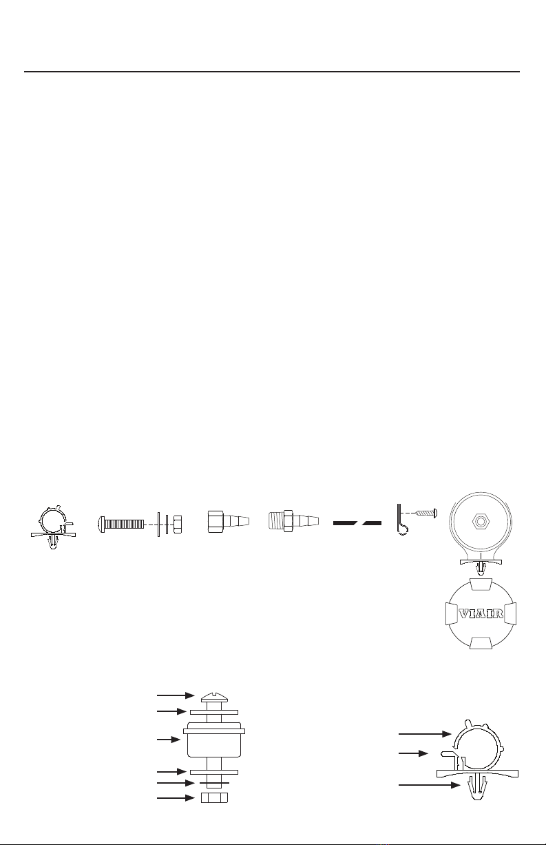
Eachofouraircompressorsandpartshavebeencarefullyproducedandpackaged.Beforeyou
begininstallation,pleasefamiliarizeyourselfwithInstallationPartsList(Fig.1)ofthismanual.
Guidelines for Selecting Mounting Location:
Theselectionofpropermountinglocationforyouraircompressorwillhelpensurealongandtrouble
freecompressorservicelife.Pleasepaycloseattentiontothefollowingguidelines:
1. Select a FLAT,UPRIGHT,ANDSECURE location where the compressor can be mounted.
2.Tomaximizeaircompressorperformance,locatecompressorasCLOSETOTHEBATTERY as
possiblesothatlengthofpositiveleadwirerequiredisataminimum.
3.ChoosemountinglocationthatisascoolaspossibleandAWAYFROMHEATSOURCES.
Thecoolertheambienttemperature,thelesschancethecompressorwilloverheat.
4.Thiscompressorismoisture&dustresistant,butNOTDIRTORWATERPROOF. Do not mount
compressorinlocationswheretheunitislikelytocomeincontactwiththeelements.
5.Forcompressorwithremoteltermounting,selectcompressor’smountinglocationwhereairline
canberoutedfromcompressorairinlettoremoteinletairlter.Makesurethattheremoteinletair
lterislocatedinadrylocation,awayfromtheelements.
6.Youwillalsowanttoselectacompressormountinglocationwheretheleaderhosebracketcanbe
mounted to leader hose.
7.Ifitisnecessarytomounttheaircompressorfurtherawayfromthebattery,suchasinside
yourvehicleorinthebedofyourpickup,useapositiveleadwireforremoteinstallation.Referto
thewiregaugeguideonthebackofthismanual.
8.Donotmountcompressornearareaswhereammableliquidsarestored.
9.Usethreadsealantforproperttinginstallation.Threadtapeisnotrecommended.
Properlysealed,recommendedtorqueis12to15ft.lbs
USER MANUAL
425C COMPRESSOR KIT

MOUNTING AND WIRING
1. Disconnectgroundcablefromvehicle’sbattery.
2. Temporarilypositiontheaircompressorinthelocationwhereitwillbemounted.
3. Routegroundwiretothenegativepostofthebatteryortoanappropriategroundingpointand
cutgroundwiretolengthasneeded.
4. Mountaircompressorwiththefoursetsofbolts,nuts,washers,andlockingwashersprovided.
(SeeFig.2forMountingInstructions)Useofthreadsealantrecommended.
5. NOTE:Forremoteinletairlterinstallation,refertoinstructionsincludedintheRemoteInletAir
FilterPack.
6. Thisaircompressormaybeequippedwithaheavydutyheatresistantleaderhose.Thisleader
hoseisdesignedtoprolongthelifeofyourairline.Donotremovethisleaderhosefromair
compressor.
7. IMPORTANT:Pleasenote,theleaderhosethatmaybeequippedwithyourcompressormay
alsohaveabuilt-ininlinecheckvalve.Donotremoveinlinecheckvalvefromleaderhoseif
soequipped.
8. Selectaproperlocationtomountleaderhosewithhosebracketprovided.Avoidlocations
whereleaderhosemaybecometangledwithwiresandotherhoses.
9. Tomounthosebracket,drillholewith3/16"drillbitandpushself–anchoringhosebracketpin
intohole.Routeleaderhosethroughhosebracketandsecurehosebypressingbracketclamp
into locked position.
10.Toremovehosefromthehosebracket,simplypressdownonthehoseclampreleasetabto
releasebracketclamp.(Fig.3)
11.Connectcompressor’spositiveleadwiretooneoftheleadsofyourpressureswitch.
12.Makesurethatyourcompressorsetupisproperlyfused.Forappropriatefusesize,refertoamp
drawofcompressorinthespecicationssectionofthismanual.
13.Alwayslocatefuseascloseaspossibletopowersource.
14.Beforeconnectingtopowersource,re-checktomakesurethatallconnectionsare
madeproperly.
15.Connectandtestcompressorsystembyrunningthecompressorforashorttimetobuildup
pressureinyourairtank.
16.Onceairpressurereachespresetcutoutpressureofyourpressureswitch,thecompressorwill
shutoff.Inspectallairlineconnectionsforleakswithsoapandwatersolution.Ifaleakis
detected,theairlinemaynotbecutsquarelyorpushedallthewayin.
(Fig. 1) 425C Compressor Installation Parts List:
A.HoseBracket(1pc)
B.MountingBolts(4pcs)
C.FlatWashers(8pcs)
D.LockingWashers(4pcs)
E.Nuts(4pcs)
F.3/8"NPTFx1/2"BarbedFitting(1pc)
G.3/8"NPTMx1/2"BarbedFitting(1pc)
H.1/2"AirLine
I.AirLineClips(3pcs)
J.Screws(3pcs)
K.RemoteInletAirFilterwithFilterElementandFilterCover(1pc)
(Fig. 2) Compressor
Mounting Hardware
B.MountingBolt
C.FlatWasher
D.LockingWasher
E. Nut
K.VibrationIsolator USER MANUAL
425C COMPRESSOR KIT
REDUCER
B
ACD E FG
I
J
K
(Fig. 3) Leader Hose Bracket
L.HoseClamp
M.ClampReleaseTab
N.Self-AnchoringPin
B
C
C
D
E
K
REDUCER
L
M
N
H

OPERATING INSTRUCTIONS
1. IMPORTANT:AlwaysoperatethecompressoratorbelowtheMAXIMUMPRESSURERATINGof
thecompressor.PleaserefertoApplication&SpecicationsSectionsofthismanualfordetails.
2.AlwaysobservetheMAXIMUMDUTYCYCLEoftheaircompressor.RefertoCompressor
ApplicationsandSpecicationsSectionsofthismanualfordetails.Operationexceeding
maximumpressureratingsand/ordutycyclewillresultindamagetotheaircompressor.
3.YouraircompressorisequippedwithanAUTOMATICTHERMALOVERLOADPROTECTOR.This
featureisdesignedtoprotecttheaircompressorfromoverheatingandcausingpermanent
damagetoyouraircompressor.Thethermaloverloadprotectorwillautomaticallycutpowerto
youraircompressorshouldtheinternaloperatingtemperatureoftheaircompressorriseabove
safelevelsduringexcessiveuse.
4.Shouldatanytimeduringuse,youraircompressorautomaticallyshutsoff;donotattemptto
restart it. Turn off power and allow unit to cool for about 30 minutes. This will allow the Thermal
OverloadProtectortoresetsoyoucansafelyresumeuseoftheaircompressor.
5.Topreventdischargeofyourvehicle’sbattery,andenhanceperformance,keepthevehicle’s
enginerunningwhileusingthecompressor.
6.Onlyoperatecompressorinwellventilatedareas.
7.Theuseofarelayisstronglyrecommendedforinstallationofthiscompressor,butnotincluded.
(40-amprelayvalueorhigherpercompressorrecommended).
MAINTENANCE & REPAIRS
1.Periodicallycheckallelectricalandttingsconnections.Cleanandtightenasneeded.
2.Periodicallycheckallmountingscrews.Tightenasneeded.
3.ReplaceAirFilterElementperiodically.Replacementfrequencydependsonoperatingfrequencyand
operatingenvironment.Forfrequentuseindustyenvironment,werecommendthatyoureplaceair
lterelementatleastonceamonth.
4.Regularlycleandustanddirtfromcompressorcoolingnsandmotorhousing.
5.Youraircompressorisequippedwithapermanentlylubricated,maintenance-freemotor.Nevertryto
lubricate the compressor.
6.AllrepairsshouldbeperformedbyManufacturerorManufacturer’sAuthorizedServiceAgenciesonly.
CAUTION:
Nevertouchtheaircompressororttingsconnectedtotheaircompressor,withbarehandsduring
orimmediatelyafteruse.Theleaderhoseandttingsconnectedtoleaderhosewillbecomevery
HOTduringandafteruse.Ifnecessary,wearheatresistantglovestohandlettings,airline,and
leader hose.
USER MANUAL
425C COMPRESSOR KIT
RELAY WIRING SCHEMATIC
Pressure Switch
86
Fused
12-Volt 30
To Ground
85
87 Compressor
(+) Lead

SPECIFICATIONS
•PartNo.42500/42502/425CAirCompressorKit/Platinum&StealthBlack(CESpec.)
MotorVoltage: 12volts
Max.CurrentConsumption: 30amps
MotorType: PermanentMagnetic
Horsepower: 1/4
Max.WorkingPressure: 175PSI
Max.DutyCycle(@72ºF&100PSI): 50%
MinutesOn/Off(@72ºF&100PSI): 30On/30Off
Max.RestartPressure: 175PSI
Max.AmbientTemperature: 158°F
Min.AmbientTemperature: -40°F
Auto.ResetThermalProtection: Yes
USER MANUAL
425C COMPRESSOR KIT

COMPRESSOR APPLICATION GUIDE
Toensurethatyougetthehighestlevelofsatisfactionfromyourcompressor’sperformance,referto
information below:
VIAIR COMPRESSOR REFERENCE CHART
COMPRESSORSERIES DUTYCYCLE MAX.WORKINGPRESSURE
(100PSI@72°F)
090SERIES 9% 120PSI
092SERIES 9% 120PSI
095SERIES 9% 120PSI
097SERIES 10% 130PSI
098SERIES 10% 130PSI
100SERIES 15% 130PSI
250IGSERIES 100% 150PSI
275SERIES 25% 150PSI
280SERIES 30% 150PSI
325SERIES 33% 150PSI
330IGSERIES 100% 150PSI
350SERIES 100% 150PSI
380SERIES 100% 200PSI
*55%
400SERIES 33% 150PSI
420SERIES 33% 150PSI
425SERIES 50% 175PSI
444SERIES 100% 200PSI
*50%
450SERIES 100% 150PSI
450IGSERIES 100% 150PSI
460SERIES 100% 150PSI
480SERIES 100% 200PSI
485SERIES 100% 200PSI
*100%
*Duty Cycle at 200 PSI and 72°F.
ABOUT COMPRESSOR DUTY CYCLE:
Dutycyclereferstotheamountoftimeacompressorcanbeoperatedinagiventimeperiodat100
PSI,andastandardambienttemperatureof72°F.Itiscommonlyexpressedinpercentageformat:
Compressorontime÷(ontime+offtime)=DutyCycle%.
ONE-HOUR DUTY CYCLE MINUTES ON /
(100PSI@72°F) MINUTES OFF
9% 5Min.On/55Min.Off
10% 6Min.On/54Min.Off
15% 9Min.On/51Min.Off
20% 12Min.On/48Min.Off
25% 15Min.On/45Min.Off
30% 18Min.On/42Min.Off
33% 20Min.On/40Min.Off
50% 30Min.On/30Min.Off
100% 1HourRunTime
NOTE:Allcompressors,regardlessofrateddutycycle,requiresufcientresttimeinbetweencycles
toallowforpartialorcompleteheatdissipation.Heatdissipationratesmayvarydependingon
ambienttemperaturesandoperatingconditions.
ABOUT RATED WORKING PRESSURE:
Toensuretroublefreeservicelifeofyourcompressor,alwaysoperatecompressorwithinrated
workingpressureofthecompressor.Neveruseapressureswitchwithahighercut-offpressurethan
compressor’sratedworkingpressure.
USER MANUAL
425C COMPRESSOR KIT

425C COMPRESSOR KIT
TROUBLESHOOTING GUIDE:
Tank pressure drops when
compressor(s)shutoff
1.Loosedraincock
2.Checkvalveleaking
3.Looseconnections
1.Tightendraincock
2.Replacecheckvalveor
compressor
3.Checkallconnectionswith
soap and water solution
andtighten
Compressorruns
continuouslyandairow
lower than normal
1.Excessiveairusage
2.Looseconnections
3.Wornpistonringorinlet
valve.
4.Cloggedairlterelement
1.Decreaseairusage
2.Checkallconnectionswith
soap and water solution
andtighten.
3.Replacecompressor
4.Replaceairlterelement
Compressorruns
continuouslycausing
safetyvalve(ifequipped)
to open
1.Faultypressureswitch
2.Defectivesafetyvalve
1.Replacepressureswitch
2.Replacesafetyvalve
Excessivemoisturein
discharge
1.Excessivewaterinairtank
2.Highhumidity
1.Draintank,tilttanktodrain.
Draintankmorefrequently
2.Movecompressortoarea
withlesshumidity,oruse
airlinelter
Compressorwillnotrun 1.Nopower,orpowerswitch
inOFFposition
2.Blownfuse
3.Motoroverheats
4.Faultypressureswitch
(ifhookeduptoa
pressureswitch).
1.Makesurecompressor
switchisON
2. Disconnect compressor
frompowersource,replace
fuse.(RefertoSpecications
section for correct
fuseamperage)
3.Letcompressorcoolofffor
about 30 minutes to allow
thermaloverloadswitchtoreset.
4.Replacepressureswitch
Thermaloverload
protector cuts out
repeatedly
1.Lackofproperventilationor
ambienttemperatureistoohigh
2.Compressorvalvesfailed
1.Movecompressortowell
ventilatedarea,orareawith
lower ambient temperature
2.Replacecompressor
Excessiveknocking
orrattling
1.Loosemountingbolts
2.Wornbearingoneccentricor
motor shaft
3.Cylinderorpistonringisworn
1.Tightenbolts
2.Replacebearingor
pistonassembly
3.Replacepistonorcompressor
CAUTION: NEVER DISASSEMBLE COMPRESSOR WHILE
COMPRESSOR IS PRESSURIZED.
USER MANUAL
PROBLEM: POSSIBLECAUSE(S) CORRECTIVEACTION

USER MANUAL
425C COMPRESSOR KIT
Wiring Diagram:
SINGLE “C” MODEL
COMPRESSOR WIRING DIAGRAM
15 Edelman
Irvine, CA 92618
949-585-0011
www.viaircorp.com
87
86
30
85
+-
Battery
To Keyed
Power Source
40A Relay
Fuse
Pressure
Switch
Rev.1
425C @ 30A
AMERICAN WIRE GAUGE GUIDE 12-VOLT:
AmpDraw
Lengthofwirefrombatteryto
compressor(infeet)
5 10 15 20
5 16 16 16 14
10 16 14 12 10
15 16 12 10 10
20 14 10 10 8
25 14 10 8 6
30 12 10 8 6
40 12 8 6 6
50 10 6 6 4
60 10 6 4 4
LIMITED WARRANTY:
VIAIRCorporationwarrantsthisproduct,whenproperlyinstalledandundernormalconditionsofuse,tobefreefromdefectsin
workmanshipandmaterialsforaperiodofoneyearfromitsoriginaldateofpurchase.Toreceivewarrantyserviceorrepair,please
contactVIAIRCorporation.
Returnsshouldbemadewithinoneyearofthedateofpurchase,afteraReturnGoodsAuthorization(RGA)numberhasbeen
assignedbyVIAIRCorporation.ToobtainRGA,faxacopyofyourreceiptto(949)585-0188.Forcompletewarrantydetails,
pleasevisit:www.viaircorp.com/warranty
PLEASE NOTE:
THISWARRANTYCOVERSPRODUCTDEFECTSONLY;ITDOESNOTCOVERINCIDENTALORCONSEQUENTIALDAMAGES
ASRESULTOFMISUSEORABUSE.
ThisManualisproprietarytoVIAIRCorporationandnoownershiprightsareherebytransferred.NopartoftheManualshallbe
used,reproduced,translated,converted,adapted,storedinaretrievalsystem,communicatedortransmittedbyanymeans,forany
commercialpurpose,includingwithoutlimitation,sale,resale,license,rentalorlease,withoutthepriorexpresswrittenconsentofVIAIR.
VIAIRdoesnotmakeanyrepresentations,warrantiesorguarantees,expressorimplied,astotheaccuracyorcompletenessofthe
Manual.UsersmustbeawarethatupdatesandamendmentswillbemadefromtimetotimetotheManual.Itistheuser’sresponsibility
todeterminewhethertherehavebeenanysuchupdatesoramendments.NeitherVIAIRnoranyofitsdirectors,ofcers,employees
oragentsshallbeliableincontract,tortorinanyothermannerwhatsoevertoanypersonforanyloss,damage,injury,liability,costor
expenseofanynature,includingwithoutlimitationincidental,special,directorconsequentialdamagesarisingoutoforinconnection
withtheuseoftheManual.
15EDELMAN•IRVINE,CA92618
TEL:(949)585-0011•FAX:(949)585-0188
www.viaircorp.com
Questo manuale è adatto per i seguenti modelli
2
Indice
Altri manuali VIAIR compressore d'aria

VIAIR
VIAIR 50001 Manuale utente

VIAIR
VIAIR 85 Manuale utente

VIAIR
VIAIR 44043-440P Manuale utente

VIAIR
VIAIR 20008 Manuale utente

VIAIR
VIAIR 100C Manuale utente

VIAIR
VIAIR 485C Manuale utente

VIAIR
VIAIR 77P Manuale utente

VIAIR
VIAIR 400P-RVS Manuale utente

VIAIR
VIAIR POWER SPORT Series Manuale utente

VIAIR
VIAIR 93 Manuale utente

VIAIR
VIAIR 28021 Manuale utente

VIAIR
VIAIR 20007 Manuale utente

VIAIR
VIAIR 45043 EXTREME SERIES Manuale utente

VIAIR
VIAIR 325C Manuale utente

VIAIR
VIAIR 400H Manuale utente

VIAIR
VIAIR 450P-RVS Manuale utente

VIAIR
VIAIR 330C-IG Manuale utente

VIAIR
VIAIR 380C Manuale utente

VIAIR
VIAIR EXTREME Series Manuale utente

VIAIR
VIAIR 15010 Manuale utente


