Vicon ADAM-6050 Manuale utente
ADAM-6050
IP Input/Output Device
User Guide
XX260-10-00
Vicon Industries Inc. does not warrant that the functions contained in this equipment will
meet your requirements or that the operation will be entirely error free or perform
precisely as described in the documentation. This system has not been designed to be
used in life-critical situations and must not be used for this purpose.
Document Number: 8009-8260-10-00 Product specifications subject to change without
notice. Issued: 9/18 Copyright © 2018 Vicon Industries Inc. All rights reserved.
Vicon Industries Inc.
Tel: 631-952-2288) Fax: 631-951-2288
Toll Free: 800-645-9116
24-Hour Technical Support: 800-34-VICON
(800-348-4266) UK: 44/(0) 1489-566300
www.vicon-security.com

2| Installation and Operation Guide
ADAM-6050 I/O Device
Introduction
The information in this manual covers installation, programming and
operation for the ADAM-6050 I/O device. The installation procedures
should only be performed by a qualified technician using approved
materials in accordance with the national Electrical Code ANSI/NFPA 70,
state and local wiring codes.
Note
Read all of the instructions completely before installing or operating this
equipment
The ADAM-6050 IP I/O device fits seamlessly into an existing Valerus
network to allow external alarm inputs and outputs to any NVR or Client
Workstation. The unit provides 12 digital inputs (sensors) and 6 digital
outputs (relays). This high-density I/O module has a built-in 10/100
based-T interface for seamless Ethernet connectivity. The unit is
compatible with Windows® XP, Vista™and 7.0 operating systems and
Valerus 18.2 and higher.
Note
The ADAM-6050 is intended to be used strictly as an input/output device
with Valerus NVRs. It has many other features that are not supported for
Valerus applications.
.

Installation
Connections are made using the RJ-45 LAN connector and the plug-in
terminal blocks for power, inputs and outputs.
Ethernet/LAN connection - RJ-45; for IP network connectivity
Digital Inputs - screw terminal for 12 digital inputs (DI0-11),
Digital outputs - screw terminal for 6 digital outputs (DO0-5).
Power –screw terminal for 24 VDC power
LEDs –two status LEDs indicate Status/Speed and
Connectivity/Communication. Red indicator blinks when module is
running and is on steadily with Ethernet speed is below 100 Mbps;
green indicator is on when connected to Ethernet and blinks when data
is being transmitted or received via Ethernet.
Note
Vicon strongly recommends the use of line conditioners, voltage regulators
and uninterruptible power supply systems (UPS) to prevent voltage
fluctuations that can affect operation and cause damage to the equipment.
Warning
Do not apply power to any unit until all connections are properly made.
Screw Terminal Block -
Inputs
Screw Terminal Block -
Inputs, Outputs, Power
RJ-45 Ethernet
LED Indicators

4| Installation and Operation Guide
Mounting
The ADAM-6050 is supplied with a mounting bracket that can be can be
installed onto any selected surface, or a DIN rail adapter, that allows it to be
mounted onto any compatible DIN rail.
Wiring and Connections
Power Wiring (power supply not included)
The ADAM-6050 is designed for a standard industrial unregulated 24 VDC
power supply, but accepts any power unit that supplies with the range of +10 -
+30 VDC. Screw terminals +Vs and GND are for power supply wiring (wires
should be at least 2 mm); +Vs (R) is for red and GND (B) is for black wire.
I/O Wiring
The ADAM-6050 uses a plug-in screw terminal block for the interface between
the I/O modules and field devices.
Connection to the Valerus System
In order to find the ADAM-6050 on the network and assign it an IP address,
download the ADAM.NET Utility software that is on the CD provided with the
unit. Once the Utility is downloaded, a shortcut to the Utility will be placed on
the PC desktop.
Notes
Installation of ADAM.NET requires that .NET Framework 1.1 or later is
installed.
The utility searches for the ADAM unit on the LAN and might not be able to
find it if it’s behind a router or a wireless device. If this happens, plug the unit
to the same switch the PC is on for the configuration steps.
Double click the shortcut icon. The ADAM-6050 (Advantech) GUI displays.
Select ADAM5000 TCP_6000 from the Module list on the left. The following
screen displays.
.

Click the Search Modules icon from the toolbar. The system will search
all ADAM-6050 modules on the network to find the IP address of this
ADAM-6050.
Note
If it is the first use of the ADAM-6050, the default IP is 10.0.0.1 and it will be
found under Others in the Module list.
Click on the unit and change IP Address, Subnet Mask and Default Gateway
according to your network settings; make sure it will be reachable from the PC
it is connecting to. The Module list will be refreshed with the new IP address of
the ADAM-6050. Select the unit and the display area will change. Select
Password tab and enter password, if required (default is 00000000); press
Apply.
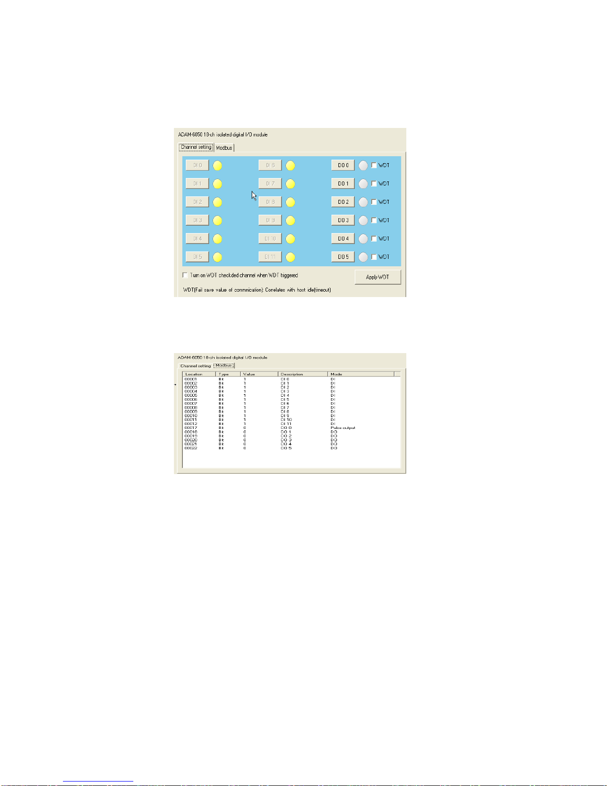
There are 2 ways to see the ADAM-6050 module. They are selected by the tab
at the top of the display area, Channel setting or Modbus. From these screens,
the value of each input can be set to be Closed (0) or Open (1) for dry contact;
for wet contact, 0 is for 0-3 VDC and 1 is for 10-30 VDC.
Module List
Search
Modules
6| Installation and Operation Guide
Channel Setting
The LED button next to the DI number displays the value of the digital input.
Modbus

Adding the ADAM-6050 to Valerus
The ADAM-6050 is supported with Valerus version 18.2 and higher.
From the Configuration tab in Valerus, select Cameras and Devices.
The following screen displays. These devices will not be auto-discovered.
Select Add Device Manually.
The following popup displays. Select the NVR you want the device assigned to
and from the Device Type dropdown, select ADAM-6050.
8| Installation and Operation Guide
Enter the IP address of ADAM-6050. The Port Number is 502; be sure your
firewall is open to this port. Click Apply to continue using the screen. Click
Apply and Close when finished.
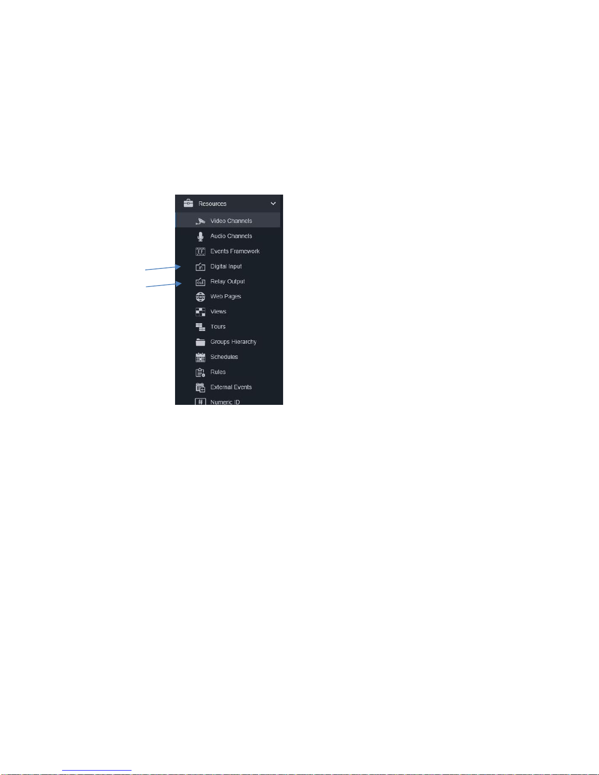
The inputs and outputs of this device will now show under Resources from the
Configuration tab along with the inputs and outputs that are on IP cameras and
encoders. Refer to the full Valerus User Guide for details on configuration of
Valerus.
Digital Inputs
Click on Digital Inputs to open the Properties screen for a list of available
digital inputs. Select the input you want to configure.
Give the input a name if needed and add any description to help identify it.
Enable the input to allow communication with it as well as appear in the
Resources list on the Monitoring screen. By default the digital input (DI) is not
visible on the Monitoring screen in the Resources list.
The current status of the input is displayed, open or closed.
Click Save.

Relay Outputs
Click on Relay Inputs to open the Properties screen for a list of available relay
outputs. Select the output you want to configure.
The output can be given a specific name and helpful identification details can
be added in the Description field.
Click the Visible button to Yes for this output to appear in the Resources list on
the Monitoring screen.
Select the Idle State (when contact is inactive) as Closed or Open and the
Mode as Momentary (maintains contact position as long as it is held) or
Latching (maintains contact position indefinitely until changed).
Click Save.

10 | Installation and Operation Guide
Troubleshooting
After setting the IP address, adding it to Valerus Cameras and Devices and
doing all other settings (i.e., port 502), the ADAM-6050 may not come online in
the system or have any available sensors when setting up alarms.
To fix this, from the Adam.net Utility, select the local IP of the device and then
click the Access Control tab. Make sure that Controlled by IP address is
selected and that no Security IP/MAC Setting is enabled (nothing in the
EnableDisable column should be checked). Click Apply.
Go back to Valerus and add the ADAM-6050 device again in Cameras and
Devices. Go back to Resources, Digital Inputs; sensors 1-12 should be
available.
If it is necessary to check the IP address of the unit, or change it, it can be
done through the Network tab.
Altri manuali per ADAM-6050
1
Questo manuale è adatto per i seguenti modelli
1
Indice
Manuali Sistema I/O popolari di altre marche

WAGO
WAGO 750-344 Manuale utente

Teknim
Teknim TWM-1887 Manuale di istruzioni

Intelligent Appliance
Intelligent Appliance IA-2662-E Manuale utente

BERGHOF
BERGHOF ECC DIO 16/16 Manuale di istruzioni

Advantech
Advantech PCM-27J3AU Manuale di installazione e funzionamento

Festo
Festo CP-E08-M12-CL Manuale utente


