vimec S11 Manuale utente
01/09/2015
Vimec s.r.l
Via Parri, 7 - 42045 Luzzara - Reggio Emilia - Italy
Tel. + 39 0522 970 666 - Fax. + 39 0522 970919
www.vimec.biz
11R
7512020/a
7512020/a
DATE ____________ APPROVED ____________
MANUAL CODE
Original instructions
S11 MODEL
USE AND MAINTENANCE Page 03 - 14
INSTALLATION INSTRUCTIONS Page 15 - 26
PARTS CATALOGUE Page 27 - 69
VIMEC reserves the right to make modications and changes to its products at any moment in response to developments in technology.
2
31/10/2012
7511020
Example
VIMEC S.r.l. “Original” Declaration of conformity
________________________________________________________
“EC” DECLARATION OF CONFORMITY
The manufacturer:
V i a P a r r i n . 7 , 4 2 0 4 5 L u z z a r a ( R . E . ) I TA
Tel. 0522/970666 r.a. Fax 0522/970919
(Name and address of the person authorised to compile the technical le:
Name: Marco Marchetti
Address: Via Parri n.7 , 42045 Luzzara (R.E.) ITALIA - Tel. +39/0522/970666)
states on his own responsibility that the vertical lifting platform type:
S11 – Serial number:
complies with the following Directives:
- Directive 2004/108/EEC “Electromagnetic Compatibility”
- Directive 2006/95/EEC “Low Voltage”
- Directive 2006/42/EEC “Machinery Directive”
Managing Director
Ing. Giuseppe Lupo
Luzzara,
7512020
3
7511020
USE AND MAINTENANCE
GENERAL CONTENTS
1. Unit and manufacturer identication Page 04
2. After-Sales Service Page 04
3. Description of unit Page 05
4. Intended and improper uses Page 08
5. Technical data Page 08
6. Preparing the lift for operation Page 09
7. Correct use of the platform lift Page 09
8. Safety systems Page 13
9. Maintenance Page 15
10. Electrical wiring diagrams Page 17
11. Vibration – Airborne noise levels Page 17
12. Information on the disposal of materials and unit parts Page 17
ENSURING SAFETY AT WORK
WARNING
This symbol highlights some essential safety instructions.
Compliance with these instructions does not mean that the others can be ignored.
Read this manual carefully before installing, starting up, using and maintaining the lift.
The most important factor in preventing accidents is care and attention when using the lift.
Comply with the information provided on the signs of all kinds applied to the lift.
Replace damaged signs immediately.
Professionals must carry out all work on the lift except for normal operating procedures.
Comply with the skill levels specied for the various procedures, symbolised as follows:
O Trained operator
OC Trained operator with specic skill
OS Skilled operator authorised by the manufacturer
An ADULT familiar with all the operating functions and precautions described in this manual must always
operate the lift
4
I - 42045 LUZZARA (RE)
Via Parri N° 7 - Tel. 0522 / 970666
7511020
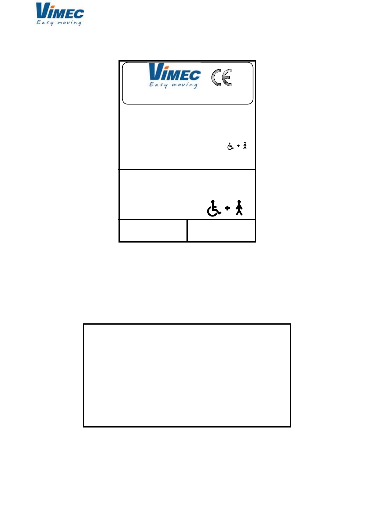
1) UNIT AND MANUFACTURER IDENTIFICATION
TYPE S11
SERIAL No. (N°) - - - -
YEAR - - - -
LOAD (kg) 400
POWER (V / A / Hz) 220 / 6 / 50
LOAD
400 kg
SERIAL No.
_ _ _ _
SERIAL No.
_ _ _ _
2) AFTER-SALES SERVICE
DEALER’S STAMP AND AUTHORISED AFTER-SALES SERVICE CONTACT DETAILS
7512020
5
c
d
a
e
f
g
a
c
b
7511020
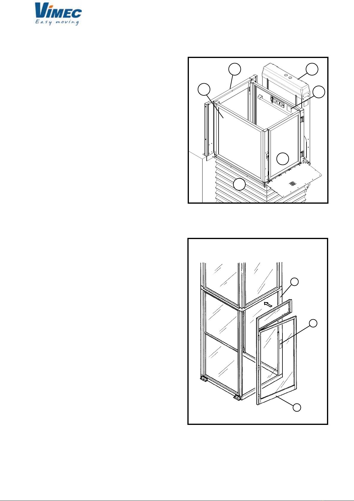
3) DESCRIPTION OF THE UNIT
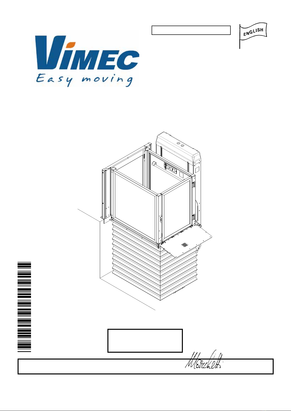
3.1) General Description - Fig. 1
The S11 lift is a platform lift designed to trans¬port
disabled persons with or without an attendant. This
machine can work both in open and closed shaft.
The shaft, if required, is an enclosed metallic (Fig. 2/a)
or masonry structure with oor doors (Fig. 2/b) enabling
the entrance to the platform. In order to guarantee the
safety of people, oor doors are locked by a safety
door lock. The opening of a door is allowed only when
the platform is at a determined oor. Upon request,
oor doors can optionally be provided with a motorized
opening and closing system. A push button control is
provided near each entrance door (Fig. 2/c).
It comprises the following:
- Upper platform with non-slip surface (Fig. 1/a)
- Column group (Fig. 1/c)
- Edge protection (Fig. 1/d)
- Bellows guard (if present) (Fig. 1/e)
- Lift gate (if present)
- Hand-operated gates at oor 1 (Fig. 1/f)
- CE marking and serial number nameplate (Fig. 1/g)
- Doors
- Locks
- Metal scaffold (if required)
FIG.1
7512020
FIG.2
6
d
e
b
c
a
f
a
b
7511020
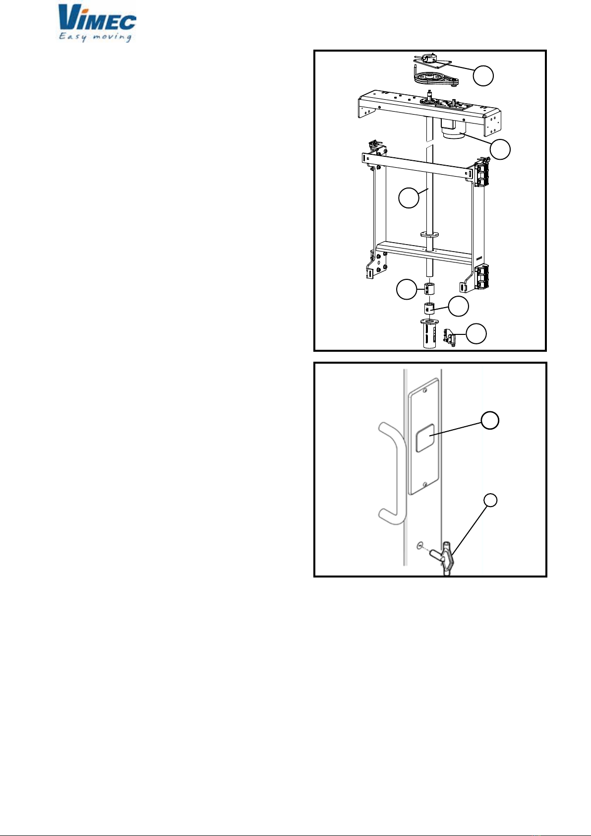
FIG.3
Lifting system - Fig. 3
The lifting system comprises:
- Motor (Fig. 3/a)
- Worm (Fig. 3/b)
- Nut screw (Fig. 3/c)
- Safety nut screw (Fig. 3/d)
- Control system (Fig. 3/e)
- Brake (if present) (Fig. 3/f)
A call/send oor control containing the following devices
is provided near each oor door (if present) (Fig. 5):
- Call push button (Fig. 5/b).
This push button allows the platform to reach that de-
terminate oor enabling the entrance.
Emergency key:
In case of oor door opening in an emergency, use
the triangular re-opening key by turning it into the free
direction (Fig. 5/a).
7512020
FIG.5
7
c
a
d
b
cfc
a
b
7511020
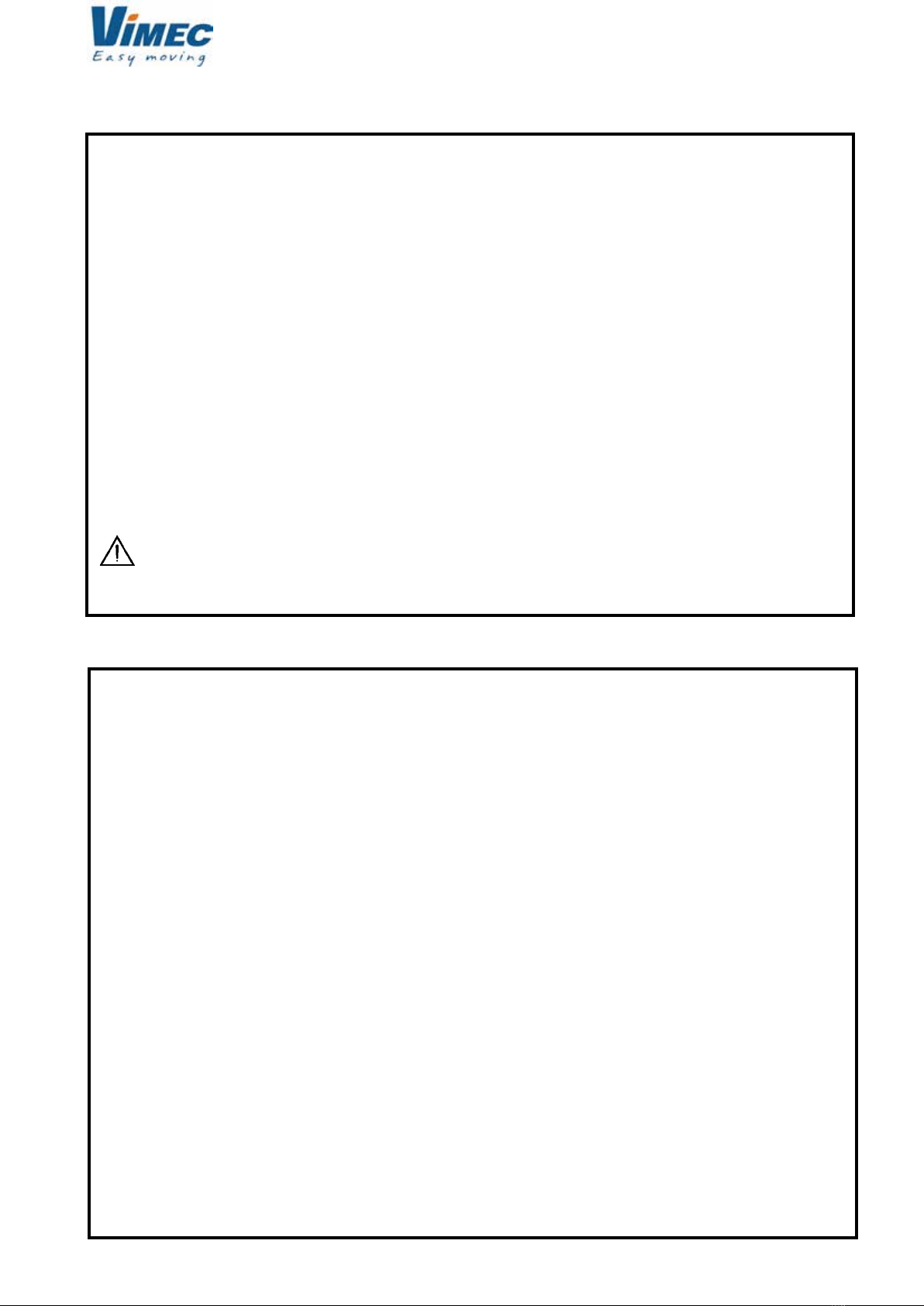
FIG.8
FIG.6
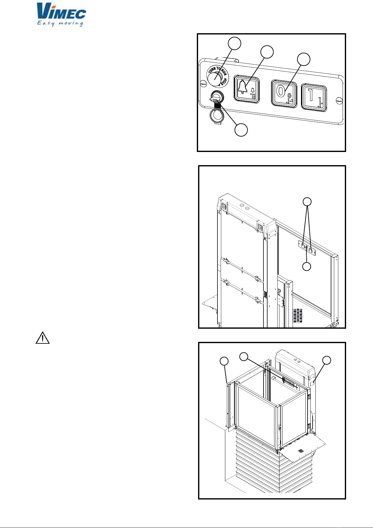
Control panels - Fig. 6
The control panel on the side guard carries the fol-
lowing:
- Emergency Button (Fig. 6/a)
- Key (Fig. 6/b)
- Up and down control buttons (Fig. 6/d)
- Alarm button (Fig. 6/c)
The rail opposite guard can carry the wireless control
panel (Fig. 7) equipped with up/down buttons (Fig. 7/a)
and key (Fig. 7/b).
3.2) Main mechanical safety features
- Gates can be opened from the outside with a special
key.
- Movement cuts out in the event of obstacles under-
neath the platform.
- Over-run device.
- Safety gear/bush.
- Photocell barriers (option)
3.3) Main electrical safety features
- STOP button on board the lift.
- Safety microswitch with over-run.
- Dual system to ensure gate closure with lock and
tamperproof microswitch.
- Movement cuts out in the event of nut screw failure.
3.4) Warning signs
The lift is tted with various warning signs:
- Nameplate stating rated payload (Fig. 8/f).
- Nameplate stating payload and those permitted to
use the lift (Fig. 8/c).
The lift system must be installed by skilled
staff authorised by VIMEC.
3.5) Reference Directives
The lift complies with the following directives:
- 2004/108/EEC “Electromagnetic Compatibility”
Directive
- 2006/95/EEC “Low Voltage” Directive
- 2006/42/EEC “Machinery Directive”
FIG.7
7512020
8
7511020
5. TECHNICAL DATA
- Lifting system
Worm screw plus motor
- Operating data
Travel direction Up/Down
Speed 0.05 m/s - 0.1 m/s
Payload See nameplate on unit
- Duty cycles
Normal duty 20 Cycles/day
- Ambient conditions from -5° to +60° C. Humidity 90% max. (use in
Temperature bathrooms and swimming-pools is
not permit¬ted).
- Electrical system
Motor 2.2 kW
Voltage 230 V (50 Hz) Three-phase / Single-phase
Auxiliary circuit at 24 VDC
IP protection degree IP 54
- Controls Hold-to-run type; on the lift: protected up and
down buttons, illuminated call buttons at oors.
All buttons are of hold-to-run type; the controls
at the oors are enabled by means of removable
keys.
4) INTENDED AND IMPROPER USES
4.1) Intended Uses
The S11 platform lift is a lift system designed for one disabled person, standing or in a wheelchair +
attendant (if any), who must be trained in the lift’s operation.
When using the lift, compliance with the instructions provided on the signs tted to it is compulsory.
4.2) Improper Uses
The user must follow the instructions provided in this manual.
The following are forbidden when using the S11 platform lift:
- Lifting anything not specied in point 4.1
- Exceeding the rated load stated on the nameplate.
- Operation by a user not trained in the use of the lift.
- Failure to follow the instructions provided on nameplates tted to the lift.
- Performance of maintenance work by anyone without the skills needed for the various procedures.
WARNING: NO MODIFICATIONS ARE PERMITTED, FOR ANY PURPOSE.
7512020
9
a
a
b
b
7511020
6) PREPARING THE LIFT FOR OPERATION
6.1) Electrical panel and installation
The customer is required to make all necessary mo-
dications required to the stairwell (before delivery),
providing a water drain in outdoor installations if requi-
red, and also to arrange for the handling of the parts
delivered.
The customer is also responsible, at his own expense,
for construction of the dedicated electricity supply line
to our panel, with conductors having gauge of at least
2.5 mm2 and differential security circuit breaker with
rated load 16A and sensitivity 0.03A type B installed
in a box with padlock xture close to the unit control
panel, having IP54 protection and earthed by means
of 2.5 mm2 cable. All expenses for making-good after
installation and any testing procedures shall also be for
the customer’s account.
The Customer shall ensure lighting of at least 50 LUX
for the landings and lift platform, with switch adjacent
to the platform.
Automatic emergency light in lift shaft 1Wx1 hour, 24
VDC emergency alarm with independent power supply
to be connected to the circuit (emergency button).
The customer shall be responsible for ensuring the
strength and nishing of walls where necessary (di-
sembarkation side).
The customer is also responsible for ensuring the
strength of the oors.
N.B.: Data are guideline and not binding.
The manufacturer reserves the right to make any chan-
ges it considers appropriate.
7) CORRECT USE OF THE PLATFORM LIFT
WARNING: READ THIS MANUAL CAREFULLY BE-
FORE USING THE PLATFORM LIFT.
7.1) Start-up
- The platform lift is started up by simply powering up the
control panel, after connecting all the cable sheaths
between the unit and the gate.
- The lift can be left constantly powered up.
Checks to be performed before using the
platform lift:
Skill level required: O - Trained operator
Frequency: Before use
7.2) Check that the load to be lifted does not exceed
the payload stated on the nameplate and is evenly
distributed over the platform surface.
FIG.9
7.3) Ensure that the load is stable.
7.4) Check that there are no foreign bodies underneath
the platform.
7.5) Check that the platform is not working in a
hazard¬ous environment (dust, salt, flammable or
explosive substances).
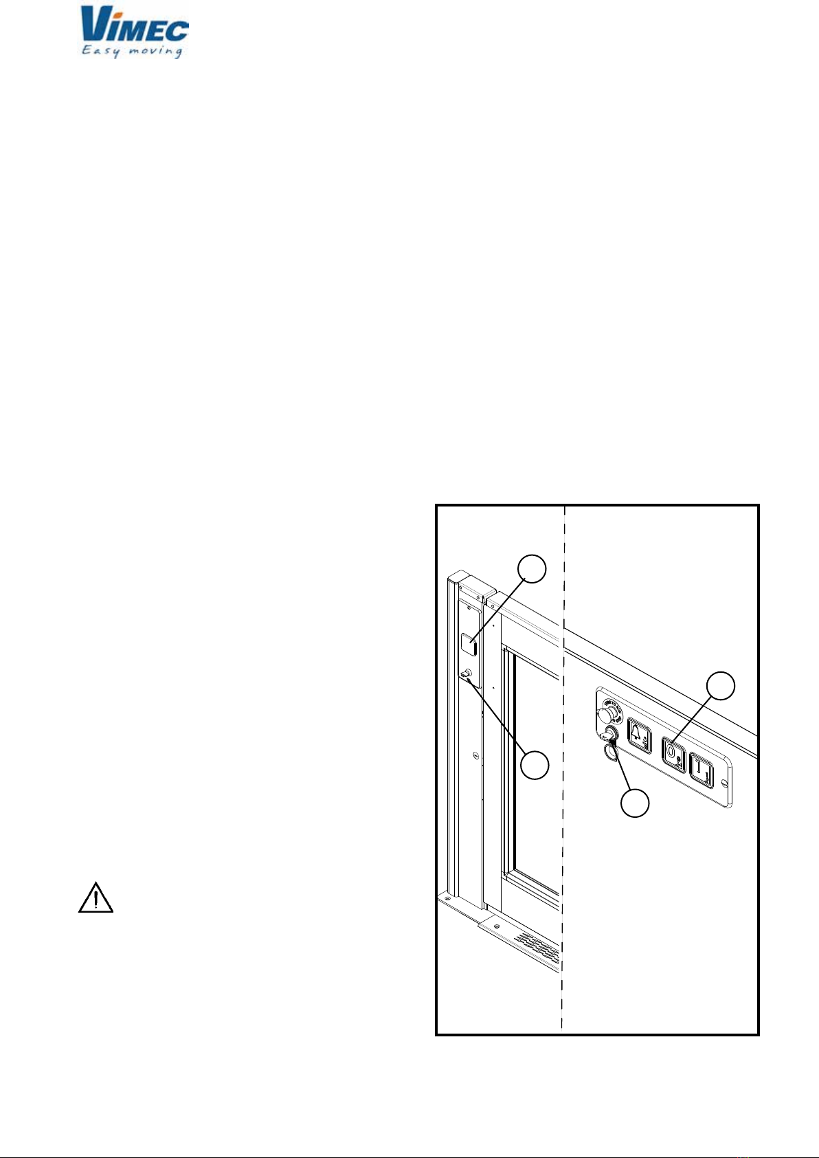
7.6) Controls at the oors
The control panel on the gate or on board of the unit
contains the following devices (Fig. 9):
- Control board master key-switch (Fig. 9/a).
- Call button (Fig. 9/b).
7512020
10
a
a
7511020
FIG.10
FIG.11
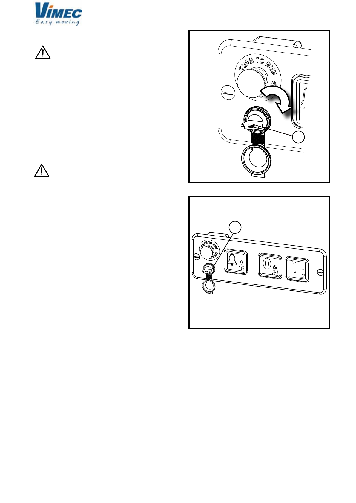
7.7) Use
While the platform lift is in motion the wheel-
chair’s brakes must be engaged and if it is electric
it must be switched off.
Floor controls:
The controls must be kept pressed throughout the
transit and cut out the lift if released. The oor locks
and the on-board control panel are only operational
if the key has been inserted.
- Insert the key (Fig. 10/a) on the control panel at the
oor and turn it to “1”.
WARNING: Even if the unit is used by more than
one person, only one key must be used.
- Press the call button (Fig. 9/b) and wait for the lock
to open.
If the platform is not at the oor, then start the “call” pro-
cedure, keep the call button pressed until the platform
reaches the oor, where it will stop and the gates will
open automatically.
If the platform is at the oor, press the but¬ton and
the gates will unlock automatically, granting access
to the platform. The gates are tted with a sprung
closing system.
On-board controls:
- Insert and turn the key on the on-board control panel.
- Select the oor required.
The up/down button must be held down until the
des¬tination oor is reached. The travel direction can
be changed at any moment. If the button is released,
the platform stops immediately. Once the destination
oor is reached, the platform stops and the gates
unlock automatically.
- Turn the key to 0 (off) and remove it.
- Red emergency stop button.
This button, provided on the control panel on the lift
only, stops the lift immediately regardless of its travel
direction.
To restore the lift to operating mode, turn the stop button
clockwise through 45°.
- Alarm
The alarm buzzer is activated by pressing the ALARM
button on the platform control board.
7.8) Operating Precautions
- The platform must be started and stopped following
the instructions provided in this manual.
- Keep the special keys for opening the gate locks and
main electrical panel in emergencies out of reach of
children or unauthorised persons.
- Always keep the documentation supplied with the unit
(manual, electrical diagrams, warranty) in a safe place.
7512020
Altri manuali per S11
1
Indice
Altri manuali vimec Sistema di sollevamento


Manuali Sistema di sollevamento popolari di altre marche


Genie
Genie Z-60/34 Manuale utente

Screen Technics
Screen Technics INTERFIT Vertical Up Lift Manuale utente

Mortuary Lift
Mortuary Lift ULTIMATE 1000 Manuale utente

Custom Equipment
Custom Equipment Hy-Brid 3 Series Manuale di programmazione

Custom Equipment
Custom Equipment Hy-Brid Lifts 2 Series Manuale di programmazione

Hy-Brid Lifts
Hy-Brid Lifts HB-P3.6 Manuale di programmazione


