Vitek VT-1916 Manuale utente

MANUAL INSTRUCTION
ИНСТРУКЦИЯ ПО ЭКСПЛУАТАЦИИ
14” STAND FAN
ith remote control
14” ВЕНТИЛЯТОР
с дистанционным
управлением
МОДЕЛЬ VT1916
1916.qxd 10.12.03 12:03 Page 2
ПРИМЕЧАНИЕ: Функция таймера может работать параллельно с несколькими
дру ими функциями вентилятора.
РЕЖИМ ПОДАЧИ ВОЗДУХА: Данный вентилятор позволит Вам получать
удовольствие от разнообразных способов подачи воздушного потока для этого
нажмите кнопку ЕЖИМ ПОДАЧИ ВОЗДУХА (WIND MODE) на пульте
дистанционного управления. Нажмите кнопку один раз для того, чтобы
установить ЕСТЕСТВЕННЫЙ режим (NATURAL), который имитирует легкий бриз
(переменная скорость вращения лопасти между высокой и низкой). Нажав
кнопку ЕЖИМ ПОДАЧИ ВОЗДУХА (WIND MODE) дважды, Вы запускаете
СПЯЩИЙ режим (SLEEP), который предусматривает снижение скорости подачи
воздуха, а после трехкратного нажатия кнопки ЕЖИМ ПОДАЧИ ВОЗДУХА (WIND
MODE), вентилятор возвращается к НО МАЛЬНОМУ режиму (NORMAL) подачи
воздуха.
ПРИМЕЧАНИЕ: НОРМАЛЬНЫЙ режим (NORMAL) подачи воздуха является
стандартной настройкой 4 он автоматически запускается сразу после включения
вентилятора.
SWING (ВРАЩЕНИЕ): Для того, чтобы головная часть вентилятора начала
вращаться, нажмите кнопку В АЩЕНИЕ (SWING) на пульте дистанционного
управления или кнопку на нижней стойке вентилятора. Для того чтобы
остановить вращение, нажмите на эту же кнопку повторно.
РУЧНАЯ РЕГУЛИРОВКА ВЫСОТЫ: Нажмите кнопку регулировки высоты,
расположенную сзади на нижней части стойки вентилятора; другой рукой при
этом аккуратно поднимайте верхнюю часть стойки. Как только желаемая высота
отрегулирована, зафиксируйте ее, отпустив кнопку.
Чтобы опустить верхнюю часть стойки, нажмите кнопку регулировки высоты, а второй рукой нажмите на кожух
двигателя. Опустите до нужной высоты. Отпустите кнопку.
РЕГУЛИРОВКА УГЛА НАКЛОНА: Для того чтобы изменить угол наклона головной части вентилятора, просто
поверните ее в желаемое положение. Стопор автоматически зафиксирует установленный угол наклона.
ЧИСТКА
• Перед чисткой отключите вентилятор от сети.
• Вытирайте пыль с корпуса сухой тряпочкой.
• Трудновыводимые пятна протрите тряпочкой, смоченной в спирте.
• Если необходимо почистить лопасти, снимите кольцо решетки, переднюю решетку, а затем открутите гайку,
которая закрепляет лопасти.
ПРИМЕЧАНИЕ: ГАЙКУ ЛОПАСТИ ВЕНТИЛЯТОРА СЛЕДУЕТ ПОВОРАЧИВАТЬ ПО ЧАСОВОЙ СТРЕЛКИ.
• После этого промойте лопасти теплой мыльной водой, затем просушите.
• Не погружайте вентилятор в воду и другие жидкости. Следите, чтобы жидкости не попадали в мотор.
• Электромотор вентилятора не требует смазки.
СПЕЦИФИКАЦИЯ
Мощность 55 Вт
Питание 220230 В ~ 50 Гц
Диаметр 14”
3 скоростных режима
Возможность установки таймера до 7,5 часов
Пульт дистанционного управления
СРОК СЛУЖБЫ ВЕНТИЛЯТОРА НЕ МЕНЕЕ 5ТИ ЛЕТ
7
РУССКИЙ
2
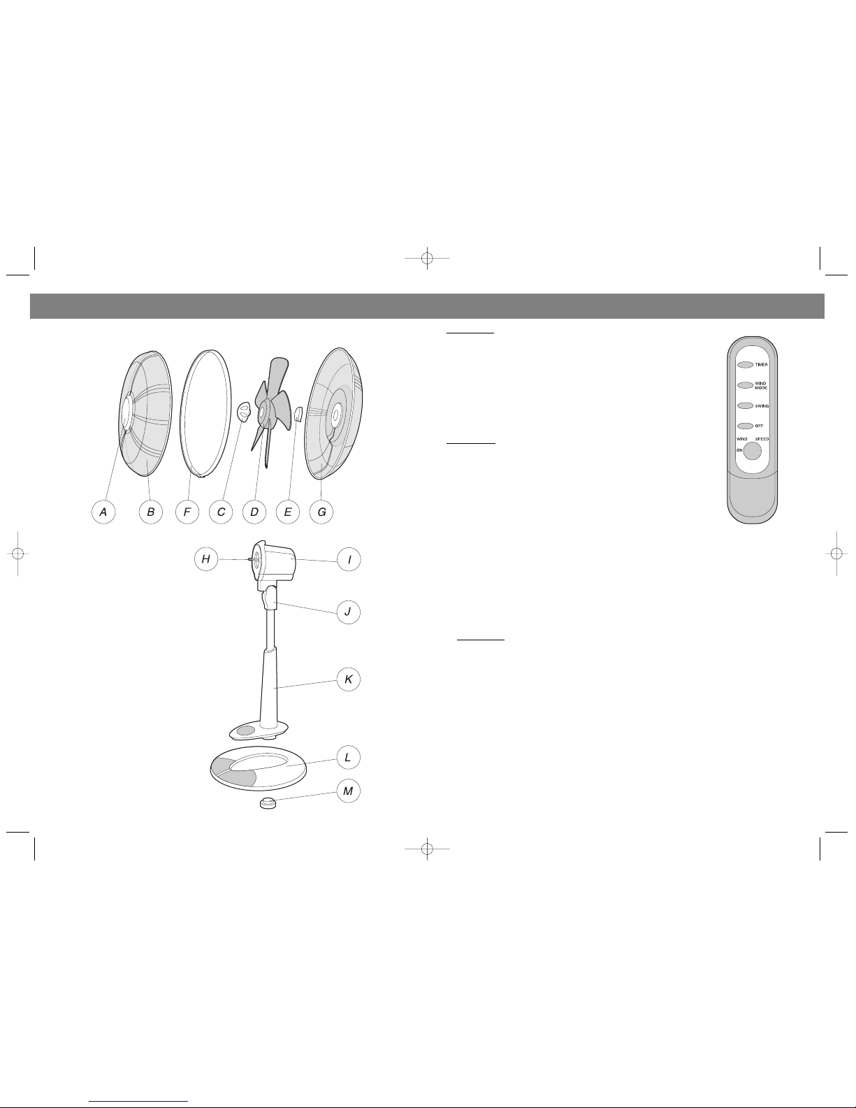
NAME OF COMPONENTS
ENGLISH
DESCRIPTION OF PARTS
A. Grill Hub
B. Front Grill
C. Fan Blade Nut
D. Fan Blade
E. Rear Grill MountingRing
F. Grill Ring
G. Rear Grill
H. Motor Shaft
I. Motor Housing
J. Upper Pole
K. Lower Pole
L. Base
M.Base Nut
1916.qxd 10.12.03 12:03 Page 4

ПРАВИЛА ЭКСПЛУАТАЦИИ
• Включайте прибор в сеть с напряжением 220230В.
• Отключайте прибор от сети после использования и перед чисткой.
• Чтобы избежать опасности удара электрическим током, не погружайте прибор в воду или другие жидкости и
следите, чтобы на него не попадала вода.
• Храните прибор в приспособленном для этого месте.
• Не оставляйте без присмотра включенный в сеть прибор.
• Не оставляйте прибор без присмотра вблизи детей, инвалидов, домашних животных.
• Используйте прибор строго по назначению, как указано в инструкции.
• Не пользуйтесь прибором, если у него повреждены шнур или вилка, или его уронили.
• Устанавливайте вентилятор на ровную устойчивую поверхность.
• Не касайтесь вращающихся частей во время работы вентилятора.
• Следите, чтобы посторонние предметы не попадали в отверстия прибора или в его решетки.
• Не блокируйте вентиляционные отверстия на корпусе мотора.
• Не пользуйтесь вентилятором без решеток.
ПРИМЕЧАНИЕ: ПРЕЖДЕ ЧЕМ ПРИСТУПИТЬ К СБОРКЕ, ПРОВЕРЬТЕ КОМПЛЕКТНОСТЬ ВЕНТИЛЯТОРА И
СООТВЕТСТВИЕ СЕТЕВОГО НАПРЯЖЕНИЯ РЕКОМЕНДУЕМОЙ ВЕЛИЧИНЕ.
Этап 1: Совместите передний выступ на нижнем конце стойки с пазои подставки. Затем опустите заднюю часть
стойки. Закрепите соединение стойки и подставки, плотно закрутив гайку подставки на нарезной части стойки.
ПРИМЕЧАНИЕ: Перед тем, как закручивать айку подставки, убедитесь, что силовой кабель, присоединенный к
нижнему концу стойки, прошел через отверстие подставки и правильно закреплен в специально
предназначенном пазе.
Этап 2: Оденьте заднюю решетку на выступы корпуса двигателя. Закрепите монтажным кольцом, повернув его
по часовой стрелке.
Этап 3: Наденьте лопасть вентилятора на вал двигателя. Убедитесь, что стержень вала двигателя совпадает с
пазом в центре задней части лопасти вентилятора. Закрепите лопасть вентилятора на валу двигателя, плотно
затянув гайку лопасти вентилятора. ПРИМЕЧАНИЕ: ГАЙКУ ЛОПАСТИ ВЕНТИЛЯТОРА СЛЕДУЕТ ПОВОРАЧИВАТЬ
ПРОТИВ ЧАСОВОЙ СТРЕЛКИ.
Этап 4: Закрепите декоративную накладку на передней решетке. Оденьте переднюю решетку на имеющийся
кронштейн на задней решетке. Наложите кольцо решетки на совмещенные края передней и задней решеток и
зафиксируйте соединение. Убедитесь, что желоб на кольце решетки совпадает с краем совмещенных решеток.
РУКОВОДСТВО ПО ЭКСПЛУАТАЦИИ
Этап 1: Установите подставку для вентилятора на сухую и ровную поверхность.
Этап 2: Подключите провод к стандартной розетке переменного тока напряжением 220 В.
Этап 3: Вставьте 2 батарейки типа AAA в специальный отсек пульта дистанционного управления в соответствии
со схемой, изображенной внутри пульта.
ON/OFF (ВКЛ/ВЫКЛ): Для того, чтобы включить вентилятор, нажмите кнопку ON (ПИТАНИЕ) на пульте
дистанционного управления или педаль на подставке вентилятора; для того, чтобы выключить вентилятор,
нажмите кнопку OFF на пульте дистанционного управления или педаль вентилятора.
SPEED (СКОРОСТЬ): Для того, чтобы отрегулировать скорость вращения
лопасти, нажмите кнопку SPEED (СКО ОСТЬ) на пульте дистанционного
управления либо педаль на подставке вентилятора. Для того чтобы установить
низкую скорость (LOW), нажмите эту кнопку один раз; для настройки средней
скорости (MEDIUM), нажмите дважды, для установки высокой скорости (HIGH),
нажмите кнопку трижды. Нажав кнопку четыре раза, Вы возвращаетесь к
начальному этапу настройки.
TIMER (ТАЙМЕР): Данный вентилятор снабжен системой установки времени
работы от 0.5 ч до 7.5 ч, при этом каждое нажатие кнопки соответствует шагу в 0.5
ч (0.5 ч, 1 ч, 1.5 ч…7.5 ч). Для настройки таймера, нажмите кнопку ТАЙМЕ (TIMER)
на пульте дистанционного управления. Для установки желаемого времени работы
вентилятора нажмите кнопку нужное количество раз.
РУССКИЙ
Thank you for purchasing Remote Control Stand Fan! Please read this instruction manual carefully before use this prod
uct and save it for further inquiry.
PLEASE READ AND SAVE THESE IMPORTANT SAFETY INSTRUCTIONS
When using electrical appliances, basic safety precautions should always be taken to reduce the risk of fire, electric
shock, and other undesired accidents, including the following:
1) Read all instructions before using the appliance.
2) To protect against electrical hazards, DO NOT immerse unit, plug or cord in water or spray with other liquids. DO NOT
use near water.
3) Close supervision is necessary when any appliance is used by or near children and disabled people.
4) Always unplug the fan before moving it, putting on or taking off parts, cleaning it, or whenever the fan is not is use. Be
sure to pull by the plug and not the cord.
5) Avoid contact with moving parts. DO NOT operate without fan grills properly in place.
6) DO NOT operate in the presence of explosive and/or flammable fumes.
7) DO NOT place fan or any parts near heated surfaces and open flames.
8) DO NOT operate any appliance with a damaged cord or plug, after the appliance malfunctions, or if it has been
dropped or damaged in any manner. Return appliance to manufacturer for examination, electrical or mechanical adjust
ment, or repair.
9) Use appliance only for intended household use as described in this manual. Any other use and use of attachments
not recommended the appliance manufacturer may cause hazards.
10) DO NOT use outdoors.
11) Keep the cord out of heavy traffic areas. DO NOT let the cord hang over the edge of a table or counter. To avoid fire
hazard, NEVER contact with hot surfaces.
12) To disconnect, grip plug and pull from wall outlet. Never yank on cord.
13) Always use on a dry, level surface.
14) This product is intended for household use ONLY and not for commercial or industrial applications.
15) DO NOT attempt to repair or adjust any electrical or mechanical functions on this unit. Doing so will void your war
ranty. The inside of the unit contains no user serviceable parts. All servicing should be performed by qualified personnel
16) WARNING: To reduce the risk of fire or electric shock, DO NOT use this fan with any solidstate speed control device.
NOTE: BEFORE ASSEMBLY, PLEASE CHECK THE CONTENTS OF THE PACKAGE AND THE RECOMMENDED VOLTAGE.
Step 1: Insert lower pole into the base until the threaded end of the pole protrudes through the opening at the base.
Secure the base and pole together by tightening the base nut to the threaded portion of the pole.
NOTE: Please make sure that the power wire which is connected with the lower pole go through the opening at the base
and rest properly in the wire groove before you tighten the base nut.
Step 2: Turn the fan blade nut clockwise and the rear grill mountingring counterclockwise to undo them. Position the
rear grill over the motor shaft; make sure the rear grill fits securely against the motor housing. Secure the rear grill in its
place using the rear grill mountingring. Turn this ring clockwise and tighten firmly.
Step 3: Slide the fan blade firmly onto the motor shaft. Make sure that the pin through the motor shaft aligns with the
groove in the back centre of the fan blade. Secure the fan blade onto the motor shaft by firmly tightening the fan blade
nut.
NOTE: TURN THE FAN BLADE NUT COUNTER4CLOCKWISE.
Step 4: Align the grill hub on the front grill, and press grills horizontally against each other. Rest the front grill on the hook
of the rear grill. Place grill ring over attached front and rear grills and tighten the connecting lock. Make sure to fit the
grooves of the grill ring over the edge of the front and rear grills.
OPERATING INSTRUCTIONS
Step 1: Set the fan base on a dry level surface.
Step 2: Plug cord into any standard 220V AC outlet.
Step 3: Insert 2 AAA batteries into the back of the remote control according to the dia
gram shown inside.
ON/OF: To turn the fan on, press the POWER button on the remote control or on the
touchkey pad, press the button a second time to turn off the fan.
SPEED: To adjust the speed, press either the SPEED button on the remote control or
on the SPEED button on the touchkey pad. Press this button first for LOW, again for
MEDIUM, and a third time for HIGH. Press a fourth time to repeat the sequence.
3
ENGLISH
6
1916.qxd 10.12.03 12:03 Page 6

5
TIMER: This fan is equipped with a timer setting from 0.5hr up to 7.5hr, 0.5hr for each
press (0.5hr, 1hr, 1.5hr…7.5hr).To activate the timer, press the TIMER button on the
remote control, or the TIMER button on the touchkey pad. Continue to press the
TIMER button to cycle through your setting options.
NOTE: Timer can be used in conjunction with several other functions.
WIND MODE: This fan enable you to enjoy various wind movements by press the WIND
MODE button on the remote control or the touchkey pad. Press this button first for the
NATURAL mode which will imitate breeze by varying the fan speeds between fast and
slow. Press the MODE button a second time, you activate the SLEEP setting which
slows the fan speed down, and when press the Mode button a 3rd time to return to
NORMAL wind. NOTE: NORMAL wind mode is the default setting; it will be activated
when you turn on the fan.
SWING: To swing the fan head, press the button marked SWING on the remote or the
SWING button on touchkey pad. Press a second time to stop swinging.
HEIGHT ADJUSTMENT: Push the height adjustment button at the back of the lower
body, while another hand gently supports the upper body. The upper body will mechan
ically glide up or glide down when given slight pressure. Release the button to secure
the height when desired position is obtained.
TILT ADJUSTMENT: To change the tilting angle of the fan head, move the fan head to
the desired position. The detent will automatically secure the angle you desire.
CLEANING/MAINTENANCE INSTRUCTIONS
Follow these instructions to correctly and safely care for your SD stand fan. Please remember:
• Always unplug the fan before cleaning or disassembling.
• DO NOT allow water to drip on or into the fan motor housing.
• DO NOT use any of the following as a cleaner: gasoline, thinner, benzene.
Fan Blade Cleaning:
STEP 1: To access the fan blade, remove the front grill and securing screw.
STEP 2: Clean the fan blade, front and rear grills with a soft, moist cloth.
STEP 3: Replace blade, tighten screw, and securely fasten the front grill.
Fan Head, Base & Pole Cleaning:
Using a soft, moist cloth, with or without a mild soap solution, carefully clean the fan base, pole, and head. Please use
caution around the motor housing area. DO NOT allow the motor or other electrical components to be exposed to water.
FAN STORAGE INSTRUCTIONS
Your fan can be stored in the offseason either partially disassembled or assembled. It is important to keep it in a safe,
dry location.
• If stored disassembled, we recommend using the original (or appropriately sized) box.
• If stored assembled or partially assembled, remember to protect the fan head from dust.
NOTICE:
1. To avoid malfunction, please DO NOT crash the fan during transportation, assembly and storage
2. After long time operation, the shell temperature will rise slightly. This is a normal phenomenon
3. If abnormal noise, smell or smoke appears during operation, please cut the power immediately, and send it to service
or qualified personnel for adjustment or repairing
SPECIFICATION
Power 55 W
Voltage 220230 V ~ 50 Hz
Bladediameter 14”
Timer 7,5 Hours
SERVICE LIFE OF THE F N NOT LESS TH N 5 YE RS
4
ENGLISH
СХЕМА ВЕНТИЛЯТОРА
УКАЗАНИЯ ПО СБОРКЕ:
A. Декоративная
накладка решетки
B. Передняя решетка
C. Гайка лопасти
вентилятора
D. Лопасть вентилятора
E. Монтажное кольцо
F. Кольцо решетки
G. Задняя решетка
H. Вал двигателя
I. Кожух двигателя
J. Верхний конец стойки
K. Нижний конец стойки
L. Подставка
M. Гайка подставки
РУССКИЙ
1916.qxd 10.12.03 12:03 Page 8
Indice
Lingue:
Altri manuali Vitek Fan

Vitek
Vitek VT-1907 Manuale utente

Vitek
Vitek VT-1909 Manuale utente

Vitek
Vitek VT-1913 Manuale utente

Vitek
Vitek VT-1915 Manuale utente

Vitek
Vitek VT-1940 Manuale utente

Vitek
Vitek VT-1904 Manuale utente

Vitek
Vitek VT-1946 Manuale utente

Vitek
Vitek VT-1918 Manuale utente

Vitek
Vitek VT-1916 Manuale utente

Vitek
Vitek VT-1909 Manuale utente

Vitek
Vitek VT-1900 Manuale utente

Vitek
Vitek VT-1912 Manuale utente

Vitek
Vitek VT-1913 Manuale utente

Vitek
Vitek VT-1938 Manuale utente

Vitek
Vitek VT-1914 Manuale utente

Vitek
Vitek VT-1902 Manuale utente

Vitek
Vitek VT-1903 Manuale utente

Vitek
Vitek VT-1934 Manuale utente

Vitek
Vitek VT-1910 Manuale utente

Vitek
Vitek VT-1919 Manuale utente


