
WALTCO GT-33 Manuale utente

80127801
Installation Manual
GT-33, 44, 55
3300, 4400, 5500 lb. Capacity Flipaway Liftgates
Last Change:
Date Pages Description
01-2022 ALL Updated mounting requirements and line drawings
Waltco Lift Corp.
Corporate Office United States
1777 Miller Pkwy
Streetsboro, OH 44241
P: 330.633.9191
F: 330.633.1418
EO:10848 Rev 03
01-2022
www.waltco.com Phone: 800.411.5685
parts@waltco.com Fax: 800.411.5684

Table of Contents
Introduction .....................................................................................................................3
1. Safety Information................................................................................................................ 4
2. Liftgate Terminology ............................................................................................................ 6
3. Basic Mounting Requirements ............................................................................................. 8
4. Installation ..........................................................................................................................11
5. Placement of Decals...........................................................................................................29
6. Lubrication Instructions .......................................................................................................32
7. Final Inspection...................................................................................................................33
8. How to Order Parts .............................................................................................................34
9. Optional Kit Instructions:
Hand Held Remote Kit.......................................................................................................35
Kit #80001433
Aux Battery Kits (Trailer) ...................................................................................................36
Improper installation of this liftgate
could result in severe personal injury or
death.
Read and understand the contents of these instructions before proceeding.
When installed, this liftgate must not alter or prevent vehicle compliance to any
existing state or federal standards.
Each chassis manufacturer’s recommendations should be consulted for
compliance.
2

INTRODUCTION
If anyone observes improper installation, improper operation, or damage, they should immediately
contact a qualified person for assistance and correction. We strongly urge anyone that has any questions
or doubts as to the installation, condition, use, operation, maintenance or repair of the liftgate to contact
us at Waltco where we have qualified personnel that will be happy to assist you. Telephone numbers and
addresses of these locations are listed in the Owner’s Manual and Installation Instructions.
INSTALLATION
Waltco liftgates should only be installed by those with sufficient basic skills to understand the
installation and operation of the liftgate, along with the equipment on which the liftgate is being installed.
Waltco’s installation instructions are not intended to give rationale for all the instructions that are given;
however, it is the intent of these instructions to give the installer both the operations and what we believe
to be the most desirable sequence of implementing these operations. These instructions can in no way
expand into an area where they will replace a qualified person, or clear thinking and a basic knowledge
that must be possessed by the installer.
It has been our experience that a knowledgeable journeyman following these instructions and
observing the operation of the liftgate will have a sufficient comprehension of the liftgate to enable this
person to troubleshoot and correct all normal problems that may be encountered.
Failure to follow the installation instructions, adjustments and mounting dimensions may result in
improper and unsafe operation of the liftgate. Unauthorized alterations of the liftgate can cause an
undesirable and dangerous condition.
OWNER’S MANUAL
The Waltco Owner’s Manual is intended to act as a guide for operation and routine maintenance but
is no way intended to encourage usage or repair of the liftgate by those who are not qualified to do so.
The contents of the owner’s manual include, but are not limited to general operation instructions,
routine lubrication, parts lists, and an outline of things that should be checked but may not be obvious to
those not technically qualified. This manual assumes the liftgate is properly installed, undamaged and
operates correctly. Improper installation, improper operation, or damage should be immediately corrected
by a qualified person.
INSPECTION
As part of the regular inspection of a liftgate and after damage or suspicion of an overload, inspect for
wear or structural damage and make necessary repairs or replacements. Check all structural components
and their attachment to the liftgate for cracked welds, loose fasteners, wear and part deformation. Check
cylinder and hose for leaks. Inspections and repairs should be made by a qualified mechanic.
REPLACEMENT PARTS
Use only Waltco original equipment replacement parts. Components of other liftgate manufacturers
may outwardly appear to be the same but are not interchangeable with Waltco products. Waltco
components are specifically designed for safety requirements, reliability and compatibility with our
products. Refer to your Waltco parts manual when ordering parts. NOTE: When ordering, give model and
serial number of liftgate.
DECALS
It is important that every vehicle that has a WALTCO Liftgate have legible DECALS clearly posted on
the vehicle and an OWNER’S MANUAL in the vehicle at all times as a guide for proper operation and
maintenance.
Additional DECALS and OWNER’S MANUALS can be obtained from WALTCO LIFT CORP.
80101388 Rev 0
3 EO 7820
3

Chapter 1 Safety Information
80101253 Rev 04 EO 6309JJ
WARNING
Read, understand, and follow all of the warning listed below.
Failure to follow these warning could result in severe personal injury or death.
• Read and understand the Owner’s Manual, all decals and warning on liftgate before operating liftgate.
• Do not operate liftgate without a thorough knowledge and understanding of the operation of the liftgate.
•Liftgate hazards can result in crushing or falling.
•This liftgate is designed for loading and unloading of cargo. If personnel are required to ride liftgate, observe
and familiarize yourself with the liftgate operation, decals and manuals. Ensure stable footing at all times.
•Do not ride liftgate with unstable loads.
•Wheeled loads must be properly retained from rolling.
•Tall, high center of gravity loads must be retained from falling over.
•Never overload liftgate:
Load platform as close to the vehicle, and towards the middle of the platform as possible. Refer to owner’s
manual and capacity decal of liftgate for maximum load and load placement.
•Keep hands and feet clear of all potential pinch points.
•Never use liftgate if it makes any unusual noise, has unusual vibration, raises or lowers unevenly, or fails to
operate smoothly.
•Never use liftgate if it shows any signs of structural damage such as cracked welds, bent or distorted
members.
•Do not attempt any repairs unless you are qualified to do so. Care should be taken when work is performed
on a disabled liftgate located near moving traffic. When possible the vehicle should be moved away from
traffic areas for repair. Precautionary measures should be taken to ensure personal safety including those
recommended in Federal Motor Vehicle Safety Standards 571.125.
•When welding to liftgate, or liftgate components, take all necessary safety precautions, including using
respiratory protection and other pertinent personal protective gear when welding harmful materials.
• All protective covers, guards, and safety devices must be in place and access doors closed before operating
liftgate.
•Do not allow anyone to stand in, or near area, in which Platform will open and close before opening or closing
Platform.
•Do not allow anyone to stand near the Platform where a falling load could land on them.
•Platform is always to be properly stored and secured for transit. See the Owner’s Manual for details.
•Take care to retain cargo during transit for liftgate Platforms which function as the tailgate or door of the cargo
area. Small objects can fall through the space between the vehicle and the folded Platform.
•A Lock-Out device or Shut-Off Switch should always be used to prevent unauthorized use of liftgate.
•For liftgates with Runners, never use liftgate if Runners do not travel freely and smoothly.
•For liftgates with Roller Lifting Chain, the Chain should be replaced every (5) five years or 15,000 cycles,
whichever comes first. Replace only with Waltco approved Roller Chain.
•Never transfer loads which exceed lifting capacity on or over any part of the Platform unless the liftgate is
equipped with a special reinforced Platform and Platform Support Bars for use when the Platform is used as
loading ramp (dock board). Refer to the “Using Platform as a loading ramp” Chapter in the Operation
Instructions of the BZ/RZ series Owner’s Manual.
•For liftgates equipped with Trailer Hitches, never exceed the rated capacity of the hitch. Do not exceed the
vehicle’s weight rating. Refer to the vehicle’s Owner’s Manual.
•Vehicle must comply with all state and federal standards.
•Follow the “Maintenance Guide” chapter in the Owner’s Manual.
4

Chapter 1 Safety Information
80101253 Rev 04 EO 6309JJ
Liftgates with Tilt Function
•Proper use of the Control Switches is of extreme importance.
•Improper use of Tilt Switch could cause load to fall from the Platform or damage the liftgate.
•Platform should be in a generally horizontal position when raising or lowering with a load.
•In any tilt position, the Platform may vary from level while raising or lowering the Platform.
Liftgates equipped with spring operated Cam Closer
•Replace Cam Release Spring every five (5) years or 15,000 cycles, whichever comes first.
RGL-Series Liftgates
•Make certain Platform Brake mechanisms are operating properly.
•The Runners are always to remain powered up against the Upstops Pins when in transit.
•Inspect Cables every three (3) months or 750 cycles, whichever comes first. Cables must be replaced if they
show signs of wear, distortion, kinking or if any broken wires are visible
•Replace cables every five (5) years or 10,000 cycles, whichever comes first.
This is the safety alert symbol. This manual uses this symbol to alert you to potential personal injury
hazards.
Obey all safety messages that follow this symbol to avoid personal injury or death.
SIGNAL WORDS
WARNING
Indicates a potentially hazardous situation, which if not
avoided, could result in death or serious injury.
Black letters on an orange background
CAUTION
Indicates a potentially hazardous situation, which if not
avoided, may result in minor or moderate injury. May
also be used to alert against unsafe practices.
Black letters on a yellow background.
NOTICE
Indicates a potentially hazardous situation, which if not
avoided, may result in property damage.
NOTICE
WARNING
CAUTION
5

Chapter 2 Liftgate Terminology
1. Deck 10. Pump unit
2. Deck extension 11. Spec tag (Includes serial number)
3. Retention ramp 12. Switches
4. Platform Handle 13. Mount Frame
5. Mount tube 14. Mount angles
6. Lift cylinder 15. Platform Pin (Torsion springs hidden behind guards)
7. Lift arm
8. Parallel arm
9. Pump & Battery box
GR10134
6

Chapter 2 Liftgate Terminology
EXPLANATION OF SPECIFICATION TAG
MODEL NO. DESCRIPTION CAPACITY
GT33 GT-33 SLIDER LIFTGATE 3300 LBS.
GT44 GT-44 SLIDER LIFTGATE 4400 LBS.
GT55 GT-55 SLIDER LIFTGATE 5500 LBS.
GR00241
SPEC TAG
7

Chapter 3 Basic Mounting Requirements
TRAILER WIDTH
GT-33/44/55 liftgates are designed for 96-102” wide
trailers.
IMPORTANT! Do not exceed maximum width of vehicle
under any circumstances.
GR10129
GR10130
DETERMINE MOUNTING DIMENSIONS
NOTE: Measure all dimensions when trailer is
unloaded and on a flat horizontal surface.
1. Determine the Bed Height. Measure from
top of trailer floor down to ground level.
2. Determine “A” dimension = Bed Thickness.
Measure from top of trailer floor to bottom of
the trailer’s cross members.
3. Determine Sill depth.
GR10131
TOP VIEW OF TRAILER
8

Chapter 3 Basic Mounting Requirements
GR10132
9
Chapter 3 Basic Mounting Requirements
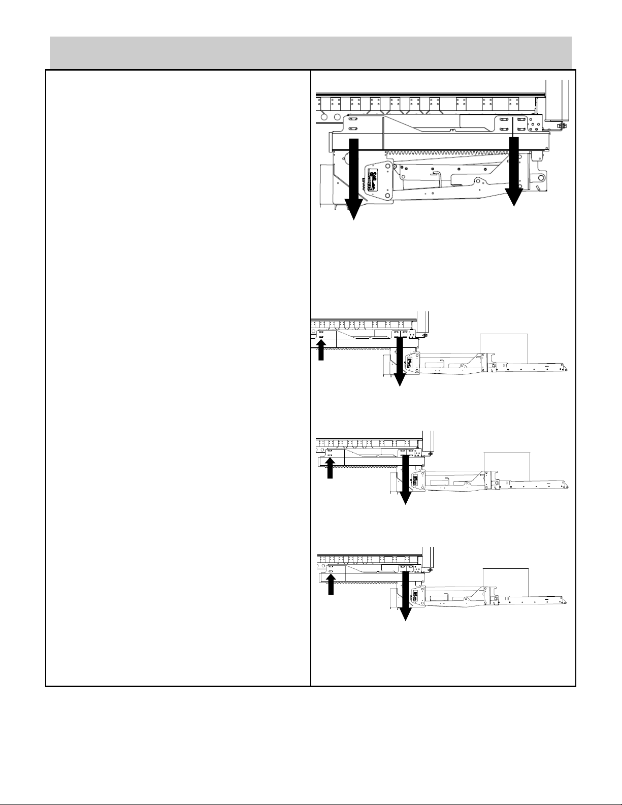
INSTALLATION WEIGHT
Make sure that trailer is capable of supporting liftgate
forces when liftgate is in stored position and when
liftgate is loaded to full capacity.
Note that forces shown here are in pounds and are
distributed over two liftgate rails.
GT- 33
GT- 44
GATE STORED
GATE
DEPLOYED
GT- 55
1,000
800
10,500
6,000
13,000
7,500
16,000
9,000
10
Questo manuale è adatto per i seguenti modelli
2
Indice
Altri manuali WALTCO Sistema di sollevamento


Manuali Sistema di sollevamento popolari di altre marche


Genie
Genie Z-60/34 Manuale utente

Screen Technics
Screen Technics INTERFIT Vertical Up Lift Manuale utente

Mortuary Lift
Mortuary Lift ULTIMATE 1000 Manuale utente

Custom Equipment
Custom Equipment Hy-Brid 3 Series Manuale di programmazione

Custom Equipment
Custom Equipment Hy-Brid Lifts 2 Series Manuale di programmazione

Hy-Brid Lifts
Hy-Brid Lifts HB-P3.6 Manuale di programmazione


