Yamato VFK2560-8 Manuale utente

Thank you for having purchased the Model VFK2560-8 class.
Before using your VFK2560-8 class, please read the instruction manual and
understand the contents well.
After reading the instruction manual, please keep it in a location where it is
easily accessible to the operator.
Instruction Manual
4 NEEDLE HIGH SPEED FLATBED FLATSEAMER
VFK2560-8 class

CONTENTS
Safety instructions ⅰ - iv
1. Name of each part 1
2. Installation 2
2.1 Semi-submerged type 2
2.1.1 Table cutting diagram 2
2.1.2 Installation 3
2.1.3 Installing supplimentary table 4
2.2 Full-submerged type 5
2.2.1 Table cutting diagram 5
2.2.2 Installation 7
2.3 Motor, pulley and belt 8
2.4 Hanging belt 9
2.5 Belt cover 9
2.6 Thread guide plate 9
2.7 Installing SC30 device 10
3. Sewing speed and rotating direction of pulley 11
4. Lubrication 12
4.1 Lubricating oil 12
4.2 Lubricating 12
4.3 Changing oil 13
4.4 Checking and replacing oil leter 13
5. Proper operation 14
5.1 Opening and closing covers 14
5.1.1 Semi-submerged type table + supplimentary table 14
5.1.2 Full-submerged type table 14
5.2 Needle system 15
5.3 Installing needles 15
5.4 Threading 16
5.5 Adjusting thread tension 17
5.6 Pressure of presser foot 17
5.7 Up-and-down position of presser foor 18
5.8 Adjusting differential feed dog 19
5.9 Adjusting stitch length 20
5.10 Height of lower knife 21
5.11 Use of lap former 21
5.12 Adjusting lapped width of upper fabric 22

CONTENTS
5.13 Adjusting the fabric lapping(both-side fabric edge trimming) 23
5.14 Adjusting SC30 device 24
5.15 HR device and SP device 25
5.16 Cleaning 26
6. Adjustments 27
6.1 Needle thread tension 27
6.2 Top cover thread tension 28
6.3 Looper thread tension 29
6.3.1 Looper thread tension 29
6.3.2 Position of looper thread take-up 30
6.4 Height of presser foot 31
6.5 Replacing presser foot spring plate 31
6.6 Replacing and adjusting knives 32
6.7 Height of needle bar 33
6.8 Looper 34
6.8.1 Installing angle and height of looper 34
6.8.2 Distance between looper and needle 34
6.9 Back-and-forth position of needle and looper 35
6.10 Needle and needle guard 36
6.10.1 Needle guard(rear) 36
6.10.2 Needle guard(front) 37
6.11 Height of feed dog 37
6.12 Needle and spreader 38
6.12.1 Spreader 38
6.12.2 Top cover thread guide 39
6.12.3 Top cover thread eyelet 39
6.12.4 Top cover thread pusher 40
6.13 Replacing presser foot 41
7. Specifications 43
Attention
The parts used for this product are subject to change without notice. If such a change is made, any part of the contents and illustrations of
this instruction manual may not conform to this product.
In preparing the instruction manual, we have made our best efforts for making it free of any error or omission. If any error or omission
should yet be found, it might not be rectified immediately.
Attention
◇ This instruction manual is designed mainly for technicians, but it is advisable that also operators read the instructions with mark to
use the machine properly.
◇ The numbers in lower left corners of figures are figure numbers. We use them in texts as needed for your reference.

i
Safety instructions
2.Installation and preparation
2-1 Instruction and training
Operators and workers, who supervise, repair or
maintain the machine head and machine unit, are
required to have the adequate knowledge and op-
eration skills to do the job safely. In order to
establish such necessary conditions, it needs
for the employer to plan and enforce the safety
education and training to those workers.
2-2 Sewing table and motor
(1) Prepare a machine table that has enough
strength to withstand the weight of the sew-
ing head and any reaction while operating.
(2) Maintain a comfortable working environment
with considering the lighting and the ar-
rangement of sewing machine so that the op-
erators can work smoothly.
(3) When installing the control box and the re-
lated parts on the sewing machine, take care
about the posture of the worker.
(4) Install the drive unit correctly according
to the instruction manual.
2-3 Wiring
(1) Never connect the plug for power supply un-
til assembly is nished.
(2) Fix the connectors securely to the sewing
machine head, motor, and electric apparatus.
(3) Do not apply excessive force to the connec-
tion cords.
(4) Connect the cords away from the driving
parts.
(5) Place the ground wire securely to the desig-
nated position on the machine head.
2-4 Before operation
(1) Take care not to attach lubricant, silicone
oil, and grease on the eyes or skin.
Keep them away from children.
(2) Be sure to ll or drop lubrication oil be-
fore operating the sewing machine.
Use the Yamato SF oil as specied.
(3) Never put your hand under the needle or near
the moving parts of the machine when turning
on power supply switch.
1. To ensure safe use
Always observe the following instructions to en-
sure the safe use of the industrial sewing ma-
chines and devices.
1-1 Application and purpose
The sewing machine is designed to improve pro-
ductivity in the sewing industry and must not be
used for other applications and purposes. Do not
use this sewing machine until it can be conrmed
that safety measures for the drive units have
been taken.
1-2 Before use
Read all instruction manuals thoroughly before
starting the use of this machine and follow
them.
Also, read the instruction manual for the installed
drive unit.
1-3 Working environment
DO NOT WORK IN THE FOLLOWING ENVIRONMENTS:
- Place where atmosphere temperature and humid-
ity give a bad influence the performance of
sewing machines.
- Outdoors and place where the sewing machines
are exposed to sunlight directly.
- Atmosphere containing dust, corrosive gases or
ammable gases.
- Place where voltage uctuation exceeds ± 10 %
of the rated voltage.
- Place where power capacity necessary for the
used motor specications cannot be secured.
- Place where strong electric or magnetic elds
are generated such as near large-output high
frequency transmitters or high frequency weld-
ing machines.
1-4 Unpacking and transportation
(1) Unpack from the top.
(2) Never hold the parts near the needle or
threading parts when removing the sewing ma-
chine head from the buffer of box.
(3) When carrying the sewing machine head, have
an assistant.
(4) Pay attention not to get excessive impact or
shock when moving the sewing machine head
with a pushcart.

ii
Safety instructions
3.Maintenance, inspection, and repair
(1) Follow the instruction manuals for mainte-
nance, inspection, and repair.
(2) Entrust the maintenance, inspection, and re-
pair to specially trained personnel.
(3) Be sure to turn off the power supply switch
and make sure the sewing machine and motor
completely stop before the maintenance, in-
spection, and repair. (If using a clutch mo-
tor, take care that the motor keeps turning
for a while even after turning off the power
supply switch.)
(4) Be sure to remove the gasket too, when the
cover removed at the maintenance, inspec-
tion, and repair. If not removed, may be
injured at the edge of gasket.
(5) Do not modify the sewing machine by the
customer's judgment.
(6) Be sure to use original replacement parts
for repairs or maintenance.
4.
Caution signs and alert pictorial markings
This instruction manual contains the following
caution signs and alert pictorial markings to
prevent you from injuring yourself or the sew-
ing machine from being damaged.
Please follow the instructions.
4-1 Meanings of caution signs
WARNING indicates potentially hazardous situ-
ations which, if not heeded, could result in
death or serious injury to you and others.
Caution indicates hazardous situations which,
if not heeded, may result in minor or moderate
injury to you and others, or may result in ma-
chine damage.
NOTE is used to emphasize essential informa-
tion.
(4) When operating a new sewing machine, make
sure the rotating direction of pulley agrees
with the rotating-direction mark.
2-5 During operation
(1) Be sure to operate the sewing machine with
the safeguards such as belt cover, finger
guard, and eye guard.
(2) Never place the nger, hair or objects un-
der the needle or close to the moving parts
while operating the sewing machine.
(3) Be sure to turn off the power supply switch
when threading or replacing the needles.
(4) Never place your hands close to the knives
when operating the sewing machine with the
trimming devices.
(5) Be sure to turn off the power supply switch
when terminating the sewing work or leaving
the sewing machine.
(6) If the sewing machine malfunctions, abnormal
sound or smell something unusual while oper-
ating, be sure to turn off the power supply
switch.
2-6 Removal
(1) Turn off the power supply switch if removed
or replaced any parts or during adjustment
of sewing machine.
(2) Do not pull the cord when removing the plug.
Be sure to hold the plug itself.
(3) A high voltage is applied inside the control
box. Turn off the power supply switch and
wait more than 5 minutes before opening the
cover.

iii
Safety instructions
4-2 Alert pictorial markings
5.Warning labels on sewing machines
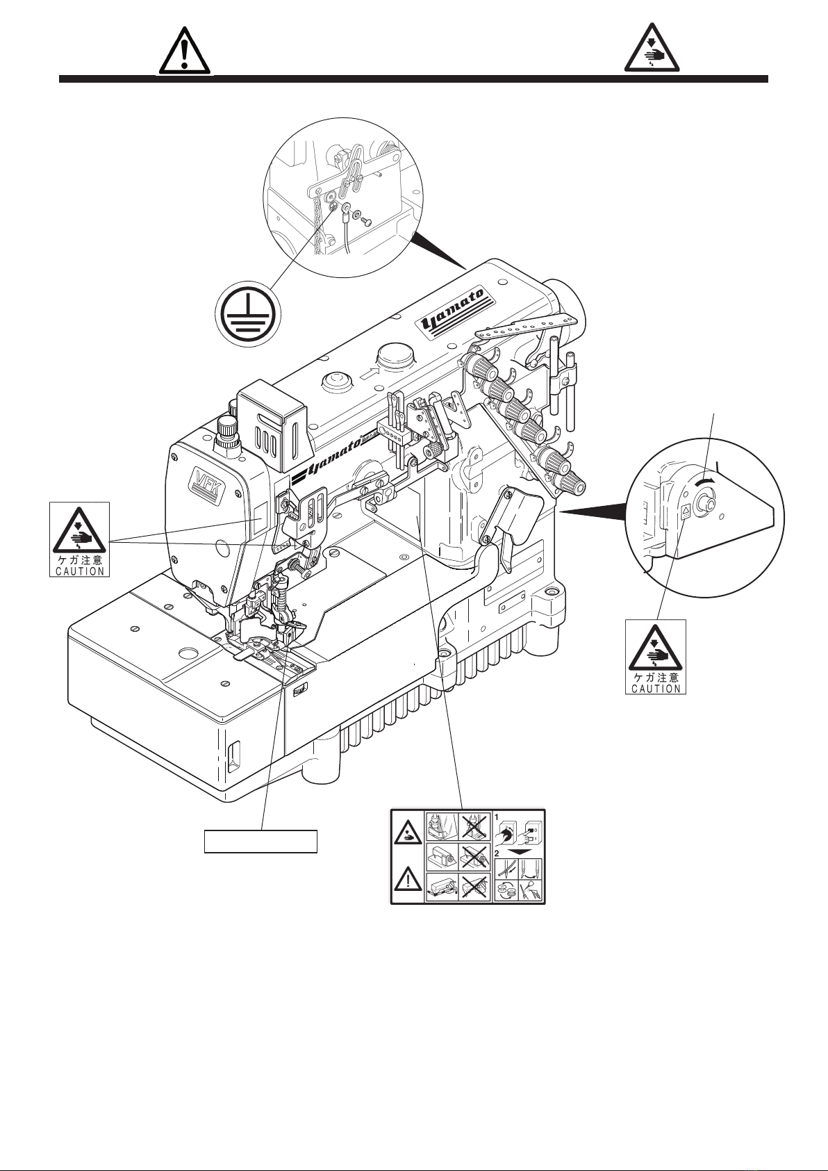
This mark indicates the warning
which, if not heeded, could re-
sult in death or Serious injury.
This mark indicates the warning
which, if not heeded, could re-
sult in death or Serious injury.
High-voltage applies in the
control box. This label indi-
cates that electric shock may be
caused.
This mark indicates the caution
which, if not grounded, the ma-
chine or device could malfunc-
tion and could result in per-
sonal injury.
This mark indicates the caution
for high temperature.
This label indicates
that removal of the
safeguards and works
except for sewing per-
formance while the
power supply switch
is on are prohibited.
(For details, see the
next page.)
High-voltage applies
in the control box.
This label indicates
that electric shock
may be caused.
This label is afxed on the
safeguards. Considering the
operation, it is not affixed
on the finger guard and eye
guard. Be sure to operate
with the nger guard and eye
guard in position.
Stepping motor and solenoid
may overheat if used con-
tinuously. To prevent a burn,
take care not to touch.
Check the rotating
direction of machine
pulley agrees with '
ROTATING-DIRECTION
SYMBOL'.
If not connected earth line,
static electricity may be
generated and inflict injury
on person. In addition, the
malfunction of electric sys-
tem may cause injury to per-
son.

iv
Safety instructions
6. Other factor which may cause injury, precaution against it
Knife mechanism
As the knife trimming mechanism is moving to
the right-and-left while sewing, if your hand
holding the fabric comes close to the mechanism,
your hand may be in danger of being struck or
pinched in the gap below.
Knife mechanism
Rotating direction symbol

1
VFK2560-8
1.Nameofeachpart
Fig. 1-1
Handwheel
Thread guide plate
SP device
Seal plug (lubrication)
Oil sight window
Needle thread take-up
Needle bar cover
Presser spring regulator
Presser foot height adjuster
Needle thread take-up guard
Feed regulating pushbutton
Side cover
Differential feed
graduation
HR cup
Presser foot
Chip guard
Lap former Supporting plate for looper
thread take-up
Front cover
Oil sight gauge
Looper thread
take-up cover
Thread tension
spring cap

2
VFK2560-8
2.1Semi-submergedtype
2.1.1 Table cutting diagram
2.Installation
Fig. 2-1
Standard
Table dimensions: 1200×595×40
Operator
center of pulley
Refer to the instruction manual of the motor
for dimensions A, B, C, and D.
Section Y -Y (1/2)
Section X -X (1/2)

3
VFK2560-8
2.1.2 Installation
4㎜
2. Installation
Fig. 2-2
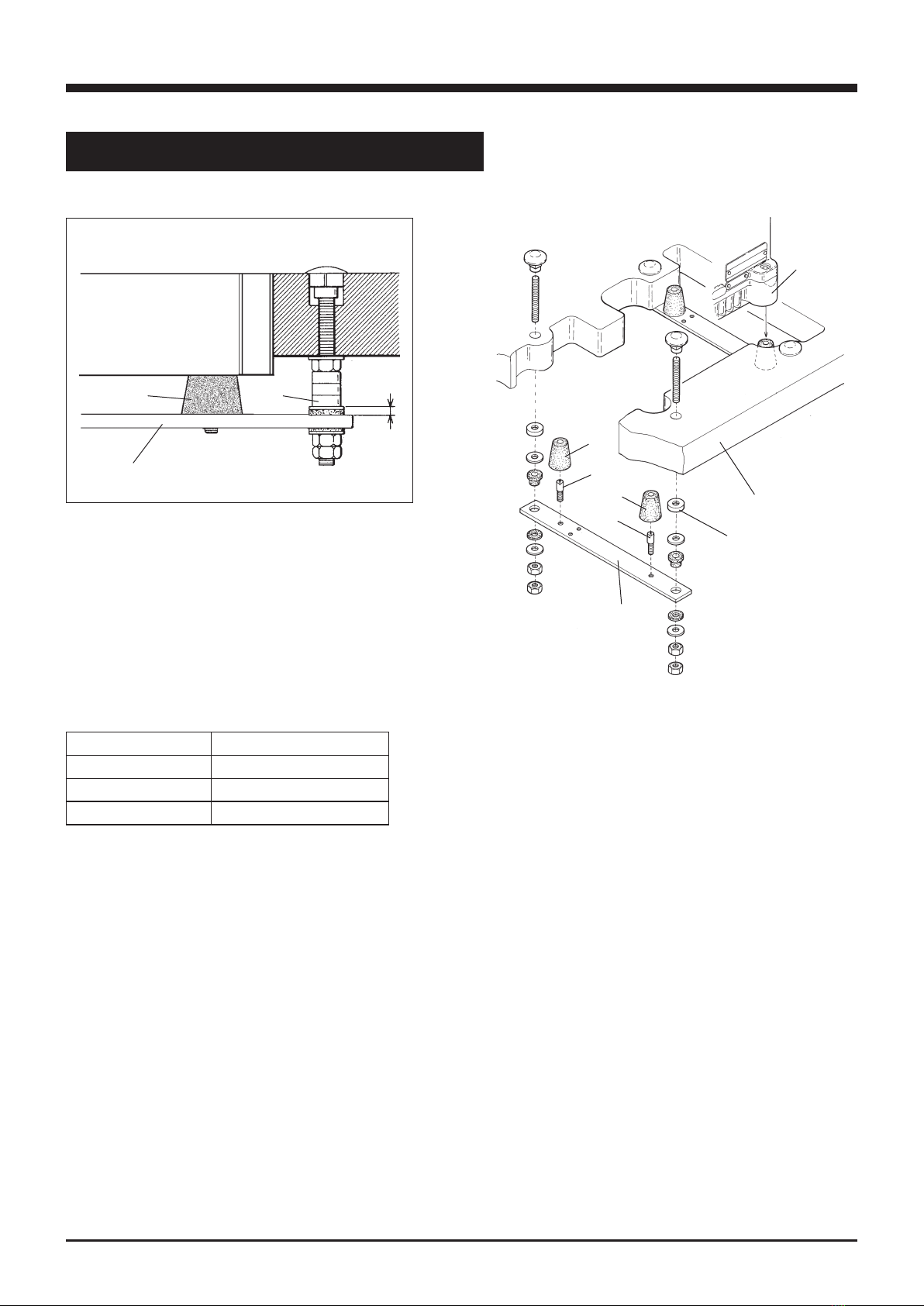
Install a machine correctly referring to Figs. 2-2 and 2-3.
Set the screws ② in the supporting board ① and cover
the screws ② with the rubber cushions ③ . Fix the the
supporting board ① to the machine table and install a
machine securely on the rubber cushions ③ .
☆ The number of spacers ④
sewing
machine
machine table
Fig. 2-3
①
④
④
③
③
③
②
②
①
Thickness of table The number of spacer ④
40 ㎜ 3 pcs. × 4=12 pcs.
45 ㎜ 2 pcs. × 4= 8 pcs.
50 ㎜ 1 pc × 4= 4 pcs.
Table 1
Indice
Altri manuali Yamato Macchina da cucire

Yamato
Yamato CC2700 Manuale utente

Yamato
Yamato CZ8000 Manuale utente

Yamato
Yamato FD-62G-20 Manuale utente

Yamato
Yamato AZ8000G class Manuale utente

Yamato
Yamato VG3511-8F Manuale utente

Yamato
Yamato AZ8600SD Manuale utente

Yamato
Yamato VG2700 class Manuale utente

Yamato
Yamato VE2700-8 class Manuale utente

Yamato
Yamato VT2500 Manuale utente

Yamato
Yamato AZ7000SDR-8 Manuale utente