ZachTek WSPR TX Mini Manuale

Document version 1.1 Page | 1
1017 WSPR TX Mini Low pass filter build
Instruction.
On the left the WSPR TX Mini as it comes delivered without a LP filter mounted - on the right with a filter
The WSPR TX Mini (product number #1017) has an unpopulated space for an output low pass filter.
This build instruction will guide the user in building and soldering the low pass filter.
Background.
The low pass filter removes the overtones from the generated RF square wave and makes the transmitter
compliant to use on one amateur band.
The user will pick what band to use and will build the filter for this band.
The filter is made up of four capacitors and three inductors. The inductors are constructed using toroidal cores
and copper wire. The capacitors are surface mount and are soldered on top of the board.
The Low Pass filter is a separate product and comes in a separate bag with product number #1021.
Document version 1.1 Page | 2
Skills required:
1. Soldering.
Estimated time for build:
0.5-2 hours depending on experience.
Preparation.
Preparing and setting up a work area.
Make sure you have the following items at hand:
1. The WSPR-TX Mini
2. Low pass filter components.
3. A soldering Iron.
4. Solder.
5. Tweezer.
Get a clear table space with a soldering iron at hand. If you print this instruction have it next to you or have a
computer next to you if you read it as you go along.
Remove the link wire on the WSPR TX Mini.
As a preparation step, you may have to remove a link wire from the WSPR board. Sometimes a wire is soldered
in to help testing it before delivery.
Just heat up the soldering points for the wire with a soldering iron and unsolder it one end at a time.

Document version 1.1 Page | 3
Checking the contents of the LP filter bag, product number 1021.
Check that the bag contains three toroidal cores, they can be black, red, yellow or other colors depending
what frequency they are made for. Typically, they are yellow.
The larger bag also contains two smaller bags that holds surface mount capacitors. To avoid getting the
capacitors mixed up I recommend that they stay in their bags until it is time to solder them to the board.
Finally, there is also a piece of wire that will be used for the toridal cores.
Checking out the schematics for the filter.
If we check the schema, we see that the inductors are called L1 to L3 and that the capacitors are designated C1
to C4

Document version 1.1 Page | 4
Checking out the placement on the circuit board.
If you check the printed text on the circuit board you will find the positions for the capacitors - C4 is not printed
due to an error in the manufacturing.
There are two capacitance values in the filter.
C1 and C4 are smaller in value than C2and C3. The exact value depends on the frequency band the filter is
made for.
To find the value check the “SMD low pass filter table” in the appendix.
As an example for a 20m filter C1 & C4 are 180pico Farad and C2 & C3 are 390pcio Farad.
As a memory guide to aid in placing the correct values, think – Higher value capacitors in the center

Document version 1.1 Page | 5
The inductors are three and the two outer ones have the same value.
In other words - L1 and L3 have the same value.
L2 is a larger value so you can use a similar mental memory guide for the inductor size, - The Higher value
Inductor goes in the center
The value of the inductors can also be found in the “SMD low pass filter table” in the appendix.
So if we for example are doing a 20m filter the L1 and L3 are 773nano Henrys and L2 in the center is 904nano
Henry.
Enough with the theory, time to warm up the soldering iron and create some solder smoke!

Document version 1.1 Page | 6
Building and mounting the LP filter.
Solder the surface mount capacitors.
There are several ways to solder the surface mount capacitor depending what tools you have. I will describe
how to do it with a normal soldering iron and solder wire.
First, apply some solder to one side of the pads that will hold the surface mount capacitor.
Do not place the SMD capacitor at this stage, only apply some small amount of solder tin to one side of the
pads.
Once you have applied some solder to one side off all the pads for C1, C2,C3 and C4, pick the two capacitors
with the highest value, they will be soldered on the inner most two pads (C2 and C3)
Remove them from the bag and the paper strip they come in. Only get the two capacitors with the highest
capacitance out at this time. Let the other two remain in their plastic bag to avoid getting them mixed up.
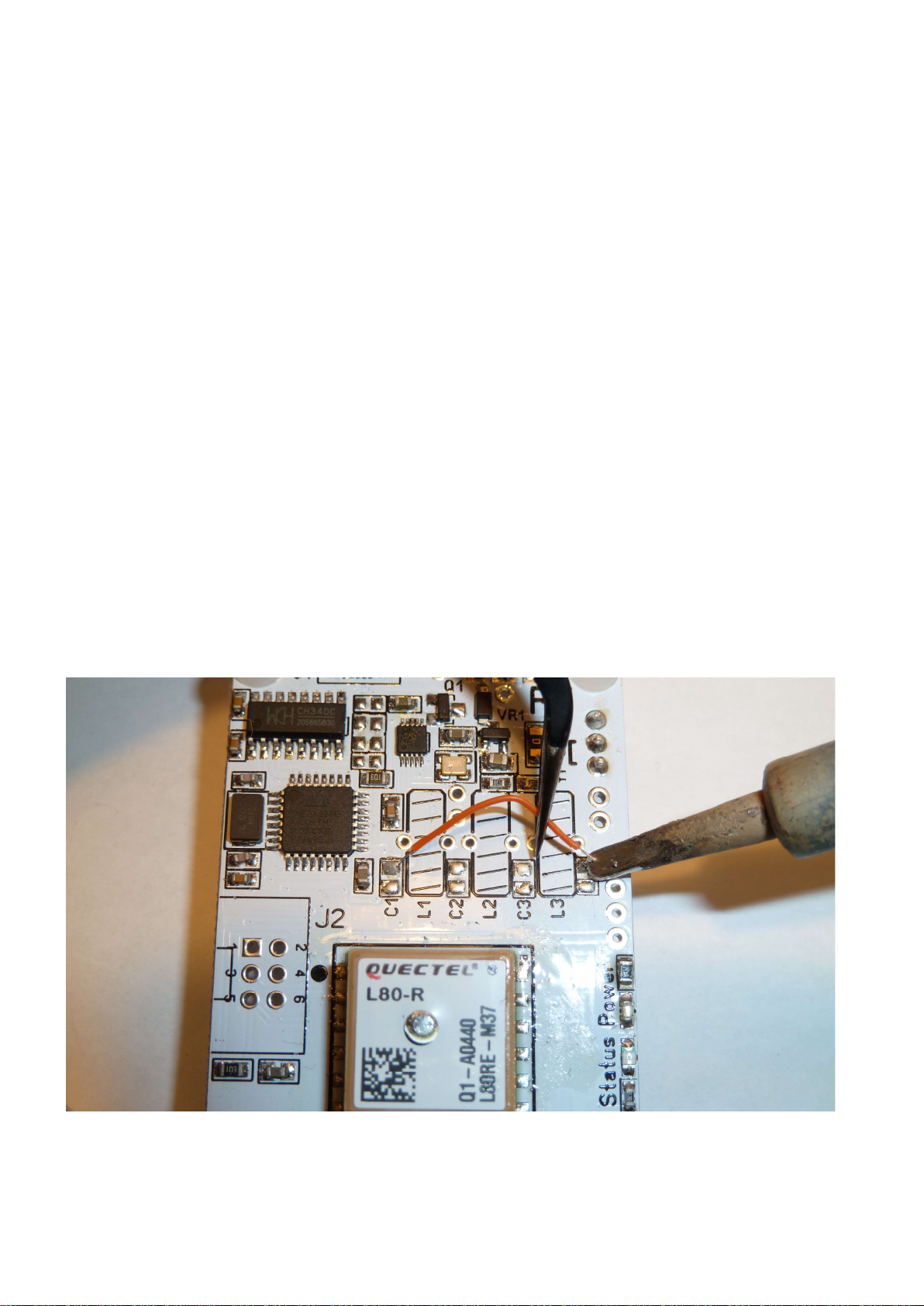
Pick up the first capacitor with a tweezer and hold it to the pad while re-heating the solder. This will solder the
capacitor on one side of the pads.

Document version 1.1 Page | 7
Do this for both capacitors (C2 & C3).
Now that innermost two capacitors are fixed and soldered to one side let’s go ahead and solder the other pad
as well.
You might want to turn the board around to get the best working angle.
Be quick when heating and applying solder so you avoid melting the opposite side or else the cap might come
lose and move about on the board.

Document version 1.1 Page | 8
OK, you have soldered in the first two caps, well done!
Now repeat this same procedure with the other two caps that will go on location C1 and C4.
That is - first solder to one pad by reheating the pad and holding the cap with a tweezer - then turn around the
board and solder the other pads.
All four of the caps are now soldered and your board should look like this (C1 to C4 now have caps).
Give yourself a pat on the back for completing 50% of the build, that is a great milestone. If you feel like
celebrating or getting yourself a treat or drink, make it a coffee, beers will be later.
You will need to be able to keep your tongue straight for the next step, time to do the coils.
Winding the Toroids.
To repeat from earlier when we discussed the inductors - there are three toroids, two have the same
inductance - same number of turns and the third one that sits in the middle of the three has a larger
inductance and thus has more number of turns.
I suggest that you start winding the middle toroid that has most turns first and solder it in before doing the
outer ones.
Start by putting the cores and wires in front of you.
Get the wire and cut it in to three pieces. You will find the length for the wires by looking in the low pass table
at the appendix of this document, the wire for the middle toroid will be slightly longer as it has more turns.
Once you have three wires, pick the longest one.
This wire will be used for inductor L2.

Document version 1.1 Page | 9
Doing the inner coil – L2
Check the low pass table in the appendix and see how many turns to use for L2.
Wind the L2 inductor, if you are unfamiliar how to wind toroidal inductors - see the winding guide in the
appendix.
After you have wound inductor L2 it’s wires are probably a bit long, like in the picture.
Cut the wires down to length leaving about 12mm/half an inch.
Now we need to get the enamel off the ends so they can be soldered.
To do that first burn the ends with a flame.

Document version 1.1 Page | 10
Now use a knife to scrape of the burnt isolation until the ends are shiny all around.
Finally tin the ends with the soldering iron and some solder.
If you have done a good job getting the enamel off it should take solder easily, if not scrape some more with
the knife and pre-tin again.
It is important to get the enamel off or else the coil might not make god contact when soldered in to the board
and as a result, you might not get a signal trough your filter.
Questo manuale è adatto per i seguenti modelli
1
Indice
Altri manuali ZachTek Trasmettitore


