ZipGrow MICROGREENS STATION Manuale utente

THE ZIPGROW™
DIY MICROGREENS STATION
ASSEMBLY GUIDE
This manual provides guidance for operating and troubleshooting the ZipGrow™
DIY Microgreens Station. Feel free to reach out to our skilled team of growers with
questions at any time. Happy growing!
– The ZipGrow team
www.ZipGrow.com
hello@ZipGrow.com
855-ZIPGROW
Copyright © 2020Copyright © 2020

Table Of Contents
OVERVIEW
Purpose of the Guide....................................................................................3
About the Microgreens Station........................................................................3
ASSEMBLY
Rack Assembly ............................................................................................4
Reservoir Placement .....................................................................................5
LED Light and Placement.............................................................................6-9
Flood Trays and Plumbing.......................................................................10-16
Pump Installation..................................................................................17-19
OPERATIONS
Microgreens Station...............................................................................20-21

Purpose of this Guide
This manual was created to walk Microgreens station owners through the installation and operation of
their Microgreens station.This manual will provide you with the information you need to install and operate
your Microgreens station eectively. If you have questions about anything covered (or not covered) in
this guide, feel free to reach out to our team via email at hello@zipgrow.com or call 1-855-ZIPGROW.
About the Microgreens Station
• Microgreens are densely planted seedlings (bigger than a sprout, smaller than a mature plant). They
are usually leafy greens or crops with dramatic avors like radishes or peas.
• Typically grown in fodder systems, seeds are planted in an even layer, germinated, and grown for a
week or two before being harvested.
• The appeal of microgreens is that they’re protable for farmers, valuable to chefs who use them as
garnishes and avor-adders, and they add a spike of avor and nutrition for consumers.
• Everything in this station has been carefully selected to help you grow microgreens without a mess
and without a hassle. We have saved you the time of searching for and shipping pieces individually.
The kit includes: (for Microgreens station base kit and add-on kit)
• (3) 4’ X 2’ Flood Trays
• (12) 10” X 20” Mesh Trays
• Bottom draw Grower’s Pump (530GPH)
• 25 Gallon Black Plastic Reservoir w/Cover
• (6) Full-Spectrum 4’ LED Strip Lights
• Danner Supreme Hydroponic Air Pump - 2W
• Airline Tubing and 6” Air Stone
• (24) BioStrate® Biobased Microgreen Propagation Felt
• ½” Rubber Hose and Various Plumbing Fittings
To order a ZipGrow™ DIY MicroGreens Station, please click here.
3
Overview
Assembly
Rack Assembly
• Assemble your rack based on manufacturer instructions.
• Leave a space of approximately 18” between the oor and the bottom shelf of the rack to ensure space
for the reservoir.
• Leave 12 inches of height clearance between all other shelves.
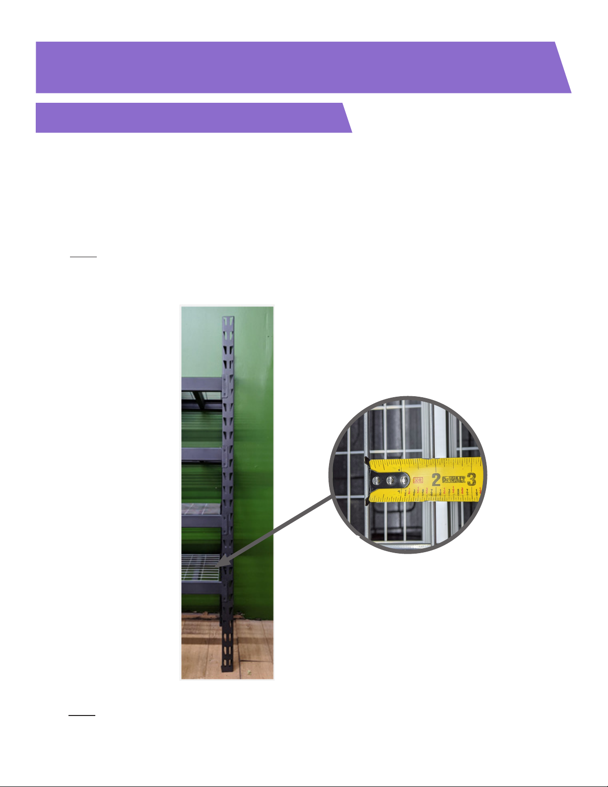
• Note: if using Husky Rack Model# ERZ782478W4C, use the shelf-hole pattern shown in Figure 1.
• When choosing a rack for this, ensure a grating space of at least 1.75”in the smallest dimension as
shown in Detail 1.A in Figure 1.
Figure 1
4
Note: this assembly guide is for the Microgreens station base kit + add-on kit. If only assembling the base
kit, the guide still applies with some minor changes that will be mentioned.
Detail 1.A
5
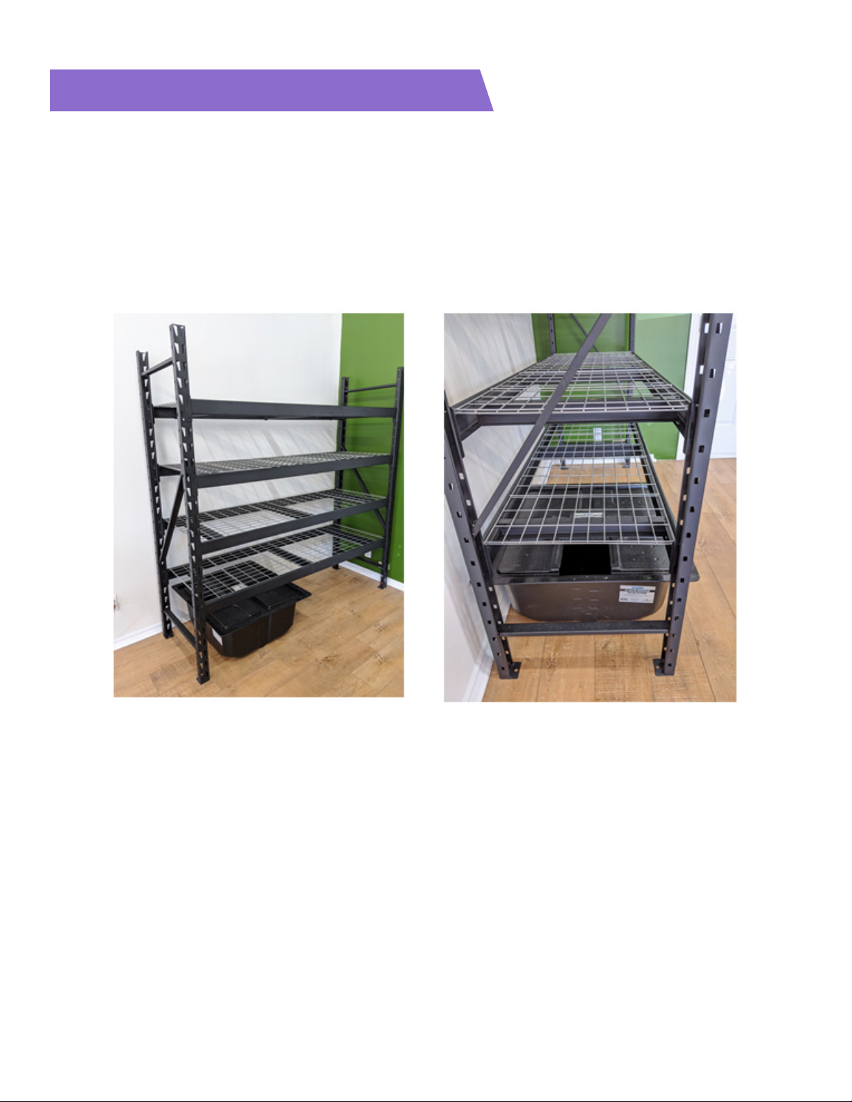
Reservoir Placement
• Place the reservoir underneath the bottom shelf towards the left side of the rack. Ensure that the reservoir
lid is oriented such that the cutout in the lid is on the left side as shown in Figures 2 & 3.
• If assembling the base unit, place the reservoir in the centre of the rack with the cutout in the lid closer to
the right side of the rack.
Figure 2 Figure 3

6
LED Light and Placement
• Unbox the six included LED lights in the long white boxes, and locate the light clips located in the small
ziploc bags - the light clips are shown in Detail 4.A in Figure 4.
• Fasten two light clips to each light, placing a light clip approximately 5” from either end of each light as
shown in Figure 4.
• Attach an S-hook to either side of each chain-link provided, as shown in Figure 5.
• Attach one S-hook to the light clips that were attached to the LED lights in the previous step, as shown in
Figure 6.
• Use the free side of the S-hooks to hang two LED lights from the bottom of each of the top three shelves
using the shelf gratings.
Figure 5
Figure 4
Detail 4.A
Figure 6
7
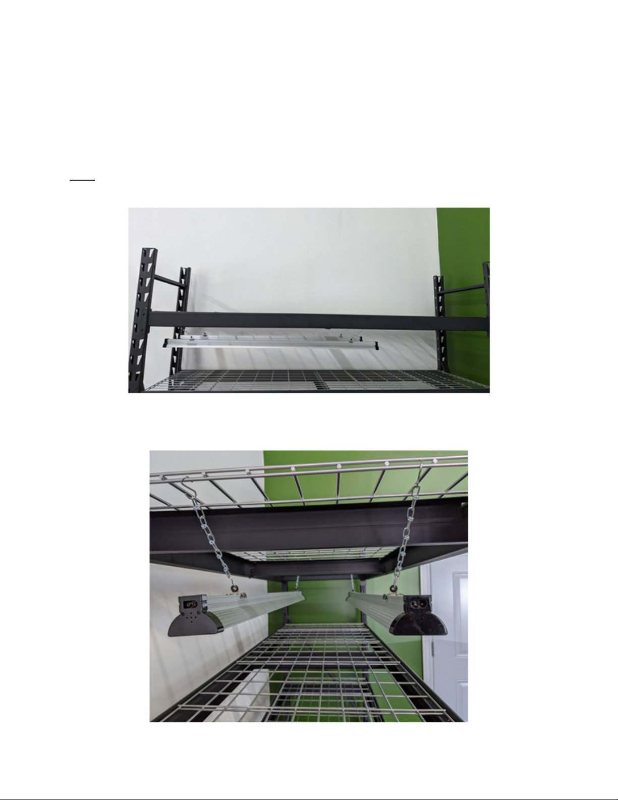
• Place the lights on the leftmost side of the rack as shown in Figure 7.
• Center the lights along the width side of each shelf as shown in Figure 8.
• These lights are daisy-chained together, so take note of the connectors on each end of the lights before
hanging them (ie. ensure that the lights on each shelf are hanging opposite of each other so that you have
access to both connector shapes from one side of the lights - as shown in Figure 8).
• Note: the lights have a rounded connector on one end, and a square connector on the other end.
Figure 7
Figure 8

8
• Use a daisy chain wire link to connect the right side of the pair of lights on the top shelf, as shown in Figure 9.
• Repeat for all three pairs of LEDs as shown in Figure 10. To keep the daisy chains out of the way, you could
run them through the shelf gratings as shown in Figure 11.
Figure 9
Figure 10 Figure 11

9
• Use a daisy chain to connect the other light on the top shelf to a light on the second shelf. Then use another
daisy chain to connect a light on the second shelf to a light on the third shelf. All lights should now be
connected to power via daisy chains, and the result will look like Figure 13.
• On the left side of the rack, connect one of the lights on the top shelf to power via the power cable
provided, as shown in Figure 12.
Figure 12
Figure 13
10
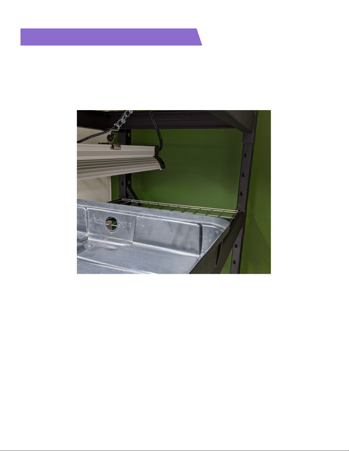
Flood Trays and Plumbing
• Locate the top tray (the top tray is the one with a circular cutout on the edge with the“Active Aqua” text, as
shown in Figure 14).
• Place this tray on the top shelf, with the “Active Aqua” side closest to the right side of the rack.
Figure 14
Indice


