Check if the DIN-Rail mounting kit is installed firmly.Step 1 Insert the bottom of DIN-Rail mounting kit (one side
Step 2 with spring support) into DIN-Rail, and then insert
the top into DIN-Rail.
Tips:
Insert a little to the bottom, lift upward and then insert
to the top.
Check and confirm the product is firmly installed onStep 3 DIN-Rail, then mounting ends.
【Disassembling DIN-Rail】
Power off the device.Step 1 After lift the device upward slightly, first shift out theStep 2 top of DIN-Rail mounting kit, then shift out the
bottom of DIN-Rail, disassembling ends.
【Power Supply Connection】
DC power supply
The series devices provide 4 bits power
supply input terminal blocks and two
independent DC power supply systems
for PWR1 and PWR2. The power supply
has nonpolarity and anti-reverse functions,
it can normally operate after reverse connection. Power
supply range: 12~48VDC
【Serial Port Connection】
3IN1 serial port
This series provide 5.08mm pitch 5 pins
industrial terminal blocks and support
RS-232/RS-485/RS-422 serial connection. Definition of pins
as the table below:
【Relay Connection】
Relay terminals are a pair of normally open
contacts in device alarm relay. They are open
circuit in normal non alarm state, closed when
any alarm information occurs. Such as: it's closed when power
off, and send out alarm. This series switches support 1
channel relay alarm information output, support DC power
alarm information or network abnormal alarm output, it can be
connected to alerting lamp, alarm buzzer, or other switching
value collecting devices for timely warning operating staffs
when alarm information occurs.
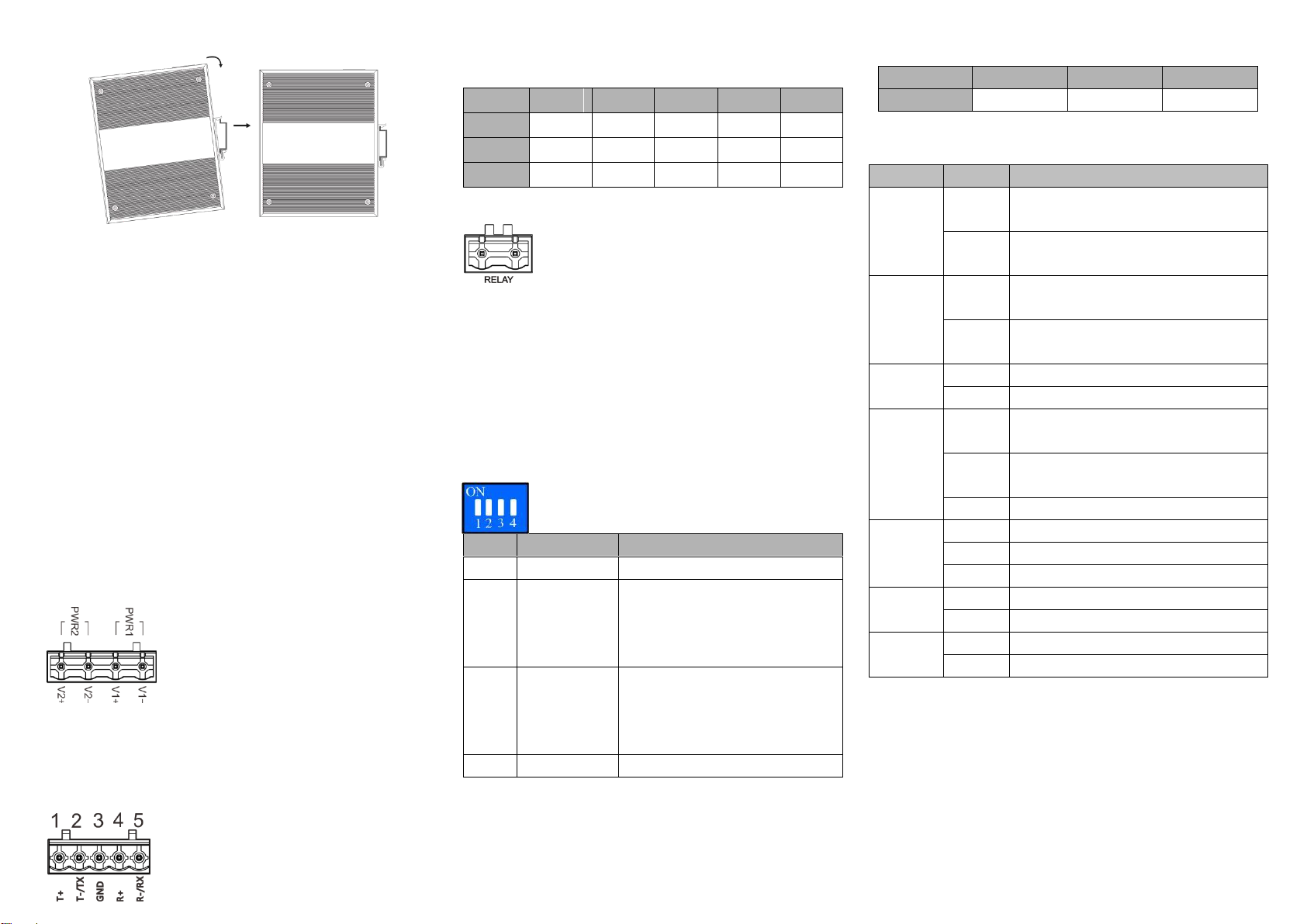
【DIP Switch Settings】
Provide 4-bits DIP switch for function setting,
where "ON" is enable valid terminal. DIP switch
definition as follows:
Set the DIP switch to ON, the
device will automatically reboot
and restore factory defaults, and
then set back the DIP switch.
Set the DIP switch to ON, the
device will be automatically
upgraded, and then set back the
DIP switch.
【Console Port Connection】
The device provides 1 channel procedure debugging port
based on serial port, and can conduct device CLI command
line management after connected to PC. The interface adopts
RJ45 port, the RJ45 pin definition is as follows:
【Checking LED Indicator】
The function of each LED is described in the table as below:
PWR1 is connected and running
normally
PWR1 is disconnected and running
abnormally.
PWR2 is connected and running
normally
PWR2 is disconnected and running
abnormally
Power supply, port link alarm
Power supply, port link without alarm
The device is powered on or the device
is abnormal.
The device is powered off or the device
is abnormal.
Ethernet port connection is active.
Ethernet port connection is inactive.
Serial port sends data abnormally
Serial port sends data normally
Serial port receives data abnormally
Serial port receives data normally
【Logging in to WEB Interface】
This device supports WEB management and configuration.
Computer can access the device via Ethernet interface. The
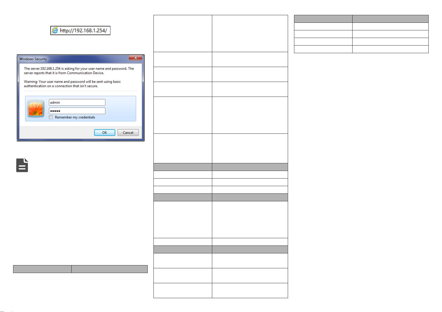
way of logging in to device’s configuration interface via IE
browser is shown as below:
Configure the IP addresses of computer and theStep 1 device to the same network segment, and the
network between them can be mutually accessed.
Enter device’s IP address in the address bar of theStep 2