Aeroflex 3020A Manuale utente
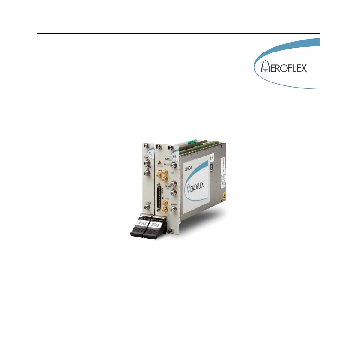
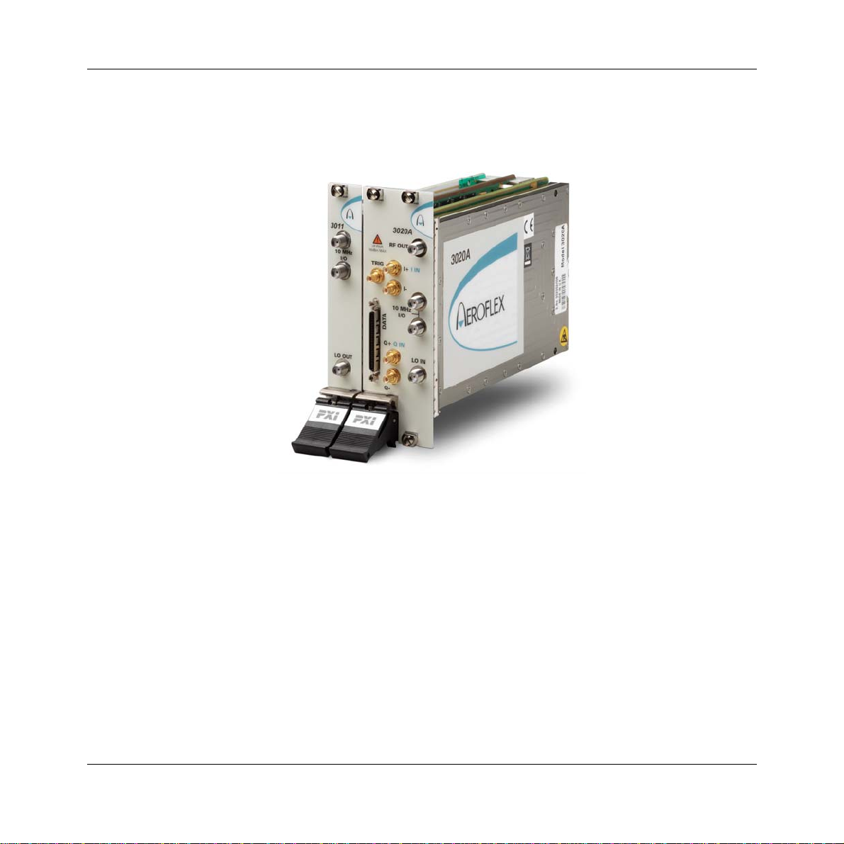
3020A Digital RF Signal Generator
PXI Module
Operating Manual
Document no. 46892/717
Issue 4
14 March 2007

PREFACE
About this manual
This manual applies to instruments with software issues of 2.0 and higher.
This manual explains how to set up and configure an Aeroflex 3020A digital RF signal
generator PXI module. Where necessary, it refers you to the appropriate installation
documents that are supplied with the module.
This manual provides information about how to configure the module as a stand-alone device.
However, one of the advantages of Aeroflex 3000 Series PXI modules is their ability to form
versatile test instruments, when used with other such modules and running 3000 Series
application software.
Getting Started with afSigGen (supplied on the CD-ROM that accompanies each module (see
Associated documentation)) explains how to set up and configure a 3020 Series RF signal
generator with a 3010 Series RF synthesizer module. Using the signal generator soft front
panel and/or dll or COM object supplied, the modules form an instrument that provides the
functionality and performance of an integrated, highly-specified signal generator, but with the
adaptability to satisfy a diverse range of test or measurement requirements.
© Aeroflex International Ltd. 2007
No part of this document may be reproduced or transmitted in any form
or by any means, electronic or mechanical, including photocopying,
or recorded by any information storage or retrieval system,
without permission in writing by Aeroflex International Ltd.
(hereafter referred to throughout the document as ‘Aeroflex’).

PREFACE
iii
Intended audience
Users who need accurately-generated signals in the VHF and UHF spectrum.
This manual is intended for first-time users, to provide familiarity with basic operation.
Programming is not covered in this document but is documented fully in the help files that
accompany the drivers and associated software on the CD-ROM.
Structure
Chapter 1 General information
Chapter 2 Installation
Chapter 3 Operation
Chapter 4 Brief technical description
Chapter 5 Acceptance testing

PREFACE
iv
Associated documentation
The following documentation covers specific aspects of this equipment:
PXI Modules CD-ROM Part no.
46886/028 Compilation containing soft front panels, drivers,
application software, data sheets, getting started
and operating manuals for this and other modules
in the 3000 Series.
3000 Series PXI
Modules Common
Installation Guide
Part no.
46882/663 Detailed information on installing modules into a
rack, external connections, powering up and
installing drivers.
3000 Series PXI
Modules Installation
Guide for Chassis
Part no.
46882/667 Explains how to set up a populated chassis ready
for use.
Getting Started with
afSigGen Part no.
46892/678 Setting up and using the signal generator
application for 3010 Series and 3020 Series
modules.
PXI Studio User Guide Part no:
46892/809 Setting up and using the universal PXI application
for system configuration and operation.

PREFACE
v
Preface
The PXI concept
VXI and GPIB systems meet the specific needs of instrumentation users but are often too
large and expensive for mainstream applications. PC-based instrumentation may cost less but
cannot meet the environmental and operational requirements of many systems.
PXI (PCI Extensions for Instrumentation) is based on CompactPCI, itself based on the PCI
standard. PCI was designed for desktop machines but CompactPCI was designed for
industrial applications, and features a rugged Eurocard format with easy insertion and
removal. PXI adds to the CompactPCI specification by defining system-level specifications
for timing, synchronization, cooling, environmental testing, and software. While PXI extends
CompactPCI, it also maintains complete interoperability so that you can use any CompactPCI-
compliant product in a PXI system and vice versa. PXI also makes use of Windows software,
VXI timing and triggering, and VXIplug&play instrument drivers to provide powerful and
affordable systems.
®is a registered trademark of Aeroflex International Inc. in the US
PXI™ is a registered trademark of the PXI Systems Alliance
Windows™, Windows XP™ and Windows NT™ are trademarks of Microsoft Corporation

PREFACE
vi
Abbreviations/acronyms
ACP(R) Adjacent Channel Power (Ratio)
ADC Analog-to-Digital Converter
ALC Automatic Level Control
AM Amplitude Modulation
ARB Arbitrary Waveform Generator
ATE Automatic Test Equipment
CW Continuous Wave
DAC Digital-to-Analog Converter
dB Decibels
dBc Decibels relative to the carrier level
dBm Decibels relative to 1 mW
EVM Error Vector Magnitude
FM Frequency Modulation
FPGA Field Programmable Gate Array
GND Ground
IQ In-phase/Quadrature
ISP In-System Programming
LO Local Oscillator
LSTB List Strobe
LVDS Low-Voltage Differential Signaling
PCI Peripheral Component Interconnect

PREFACE
vii
Pk-Pk Peak-to-Peak
PXI PCI eXtensions for Instrumentation
RF Radio Frequency
RMS Root Mean Square
SDRAM Synchronous Dynamic RAM
SFP Soft Front Panel
SMA SubMiniature version A (connector)
SMB SubMiniature version B (connector)
TDMA Time Division Multiple Access
TRIG Trigger
TTL Transistor-Transistor Logic
UUT Unit Under Test
VCO Voltage-Controlled Oscillator
VHDCI Very High Density Connector Interface
VSWR Voltage Standing-Wave Ratio
VXI VMEbus Extension for Instrumentation
1-1
Chapter 1 GENERAL INFORMATION
Introduction
Welcome to the operating manual for the 3020A Digital RF Signal Generator.
The 3020A Digital RF Signal Generator operates over a frequency range of 250 MHz to
2.7 GHz and a level range of +5 dBm to −120 dBm. The RF output may be continuous wave
(CW) or modulated. Modulation can be internal analog AM/FM, internal and external digital
IQ, or external vector (when Option 01 is fitted).

GENERAL INFORMATION
1-2
Internal digital IQ modulation is supported by a built-in dual-channel arbitrary waveform
generator (ARB). This ARB is compatible with waveforms designed or packaged using the
®software application. Differential baseband I and Q outputs from the ARB are
available as an option. External digital IQ modulation is supported via an LVDS data
interface. An external synthesizer provides a local oscillator input signal: the 3010 Series RF
Synthesizer is recommended. The two modules together occupy only three slots in a 3U PXI
chassis.
Applications
The 3020A is ideal for generating complex modulated waveforms for digital radio
communications test and measurement applications, satellite and terrestrial TV broadcasting,
military communications and WLAN. When the 3020A is used with other Aeroflex PXI RF
modules, complete RF test systems can be implemented. High RF accuracy, stability and
repeatability ensure consistent measurement results, helping to improve manufacturing yield.
Wide frequency coverage
The 3020A’s frequency range makes it ideal for multi-purpose applications in UHF radio
communications, especially important when testing multi-mode cellular terminals.
Low noise and frequency-agile
When used with a 3010 Series synthesizer, the 3020A provides the low noise and high
switching speed necessary for high-productivity RFIC testing or the stimulus to frequency-
hopping radios.
RF level accuracy and bursting
The 3020A maintains accurate RF output levels to typically ±0.3 dB, and can generate
modulated RF bursts to simulate TDMA signal characteristics.
IQ digital modulation
The 3020A provides high-quality digital modulation suitable for all common radio
communications applications, either from the internal ARB or from an external source via the
LVDS data connector.

GENERAL INFORMATION
1-3
Analog I &Q inputs and outputs (optional)
The 3020A can provide baseband I and Q output and CW RF output simultaneously.
Differential analog I and Q outputs from the ARB are provided, with control of differential
output level, DC bias and offset voltage.
IQ vector modulation
Analog I and Q inputs can be used to generate wideband vector modulation from external
analog I and Q sources such as test instruments and device outputs.
Arbitrary waveform generator (ARB)
The ARB can store 32 MSamples, either as a single long waveform or any number of smaller
waveforms up to the capacity limit of the sample memory. Waveforms transfer quickly
between the PXI controller and the ARB because of the wide bandwidth of the PCI backplane.
Playback times of more than 30 minutes are possible, longer if ARB sequencing is used.
ARB sequencing
ARB sequencing provides a method for extending the effective ARB sample memory as well
as providing a flexible way to compile test sequences. You can define up to 128 sequence
steps, each of which defines an ARB file from a selection of 64, and plays it a chosen number
of times before continuing on to the next file in the ARB sequence.
Triggering and synchronization
The 3020A provides flexible, configurable triggering facilities from inputs on the front panel
or the PXI backplane. Triggers can be used for addressed selection or stepped incrementing
of list mode. Triggers can generate power bursts and can be programmed into ARB
waveforms to provide trigger outputs for other instruments.
A configurable routing matrix provides flexibility in how you interconnect signals on the PXI
backplane, the LVDS and TTL front-panel inputs, and the module’s internal functions.
Predefined routing scenarios can be loaded, or new scenarios created to meet particular
requirements.
Questo manuale è adatto per i seguenti modelli
1
Indice
Altri manuali Aeroflex Unità di controllo

Aeroflex
Aeroflex 3000 Series Manuale utente

Aeroflex
Aeroflex 3010 Series Manuale utente

Aeroflex
Aeroflex 3060 Series Manuale utente

Aeroflex
Aeroflex 3020 Series Manuale utente

Aeroflex
Aeroflex 3035C Manuale utente

Aeroflex
Aeroflex 3035 Manuale utente

Aeroflex
Aeroflex SmartStep 8310 Manuale utente

Aeroflex
Aeroflex 3065 Manuale utente
Manuali Unità di controllo popolari di altre marche

Festo
Festo Compact Performance CP-FB6-E Manuale elenco delle parti

Elo TouchSystems
Elo TouchSystems DMS-SA19P-EXTME Manuale utente

JS Automation
JS Automation MPC3034A Manuale utente

JAUDT
JAUDT SW GII 6406 Series Guida rapida

Spektrum
Spektrum Air Module System Manuale utente

BOC Edwards
BOC Edwards Q Series Manuale utente


