AR SMOOTH FLITE 16 RRS Manuale utente

Smooth Flite 16
RRS
Version User Guide

2
Table Of Contents
Introducon ---------------------------------------------------------------------------------------------------------------------4
Important Points ---------------------------------------------------------------------------------------------------------------4
Features --------------------------------------------------------------------------------------------------------------------------5
Installaon and Mounng Instrucons ----------------------------------------------------------------------------------6
Mounng the Smart Display ------------------------------------------------------------------------------------------------7
General Usage and Screen Informaon ----------------------------------------------------------------------------------8
Main Menu ----------------------------------------------------------------------------------------------------------------------9
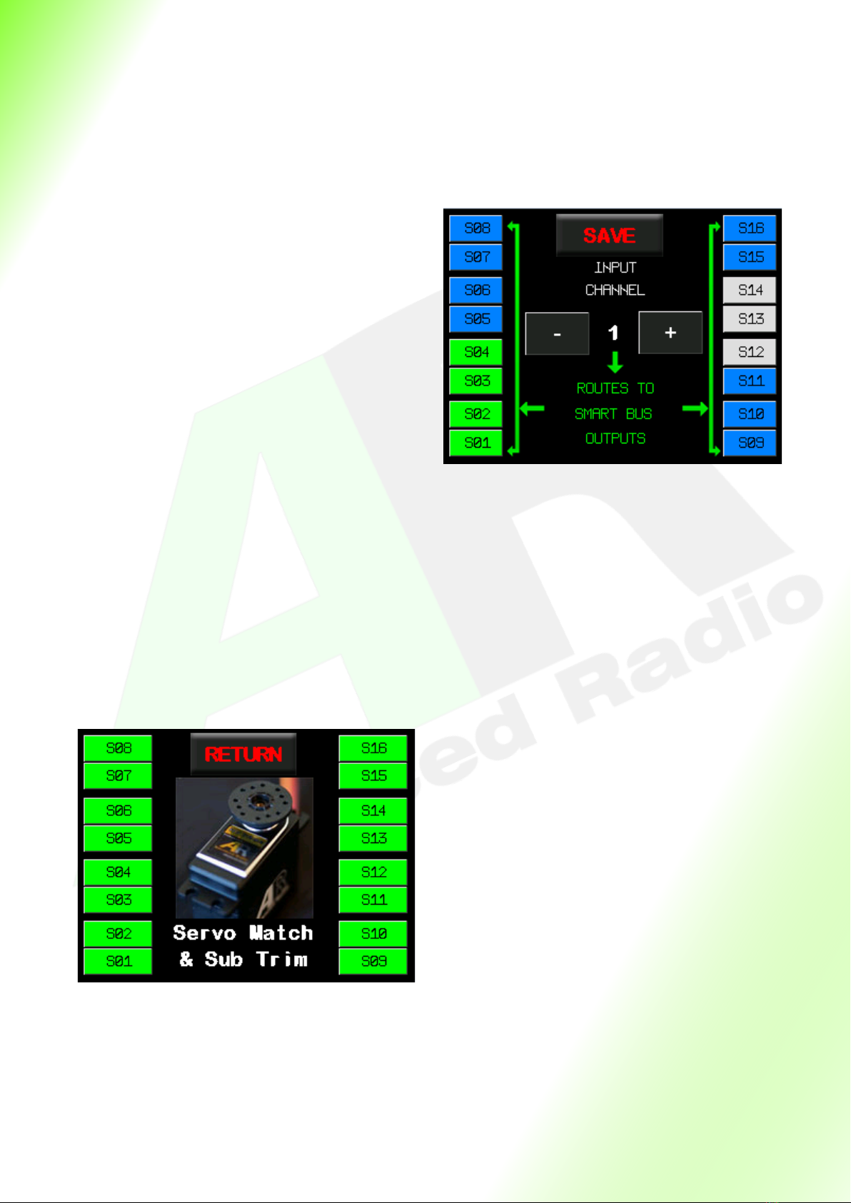
Input to Output Roung---------------------------------------------------------------------------------------------------- 10
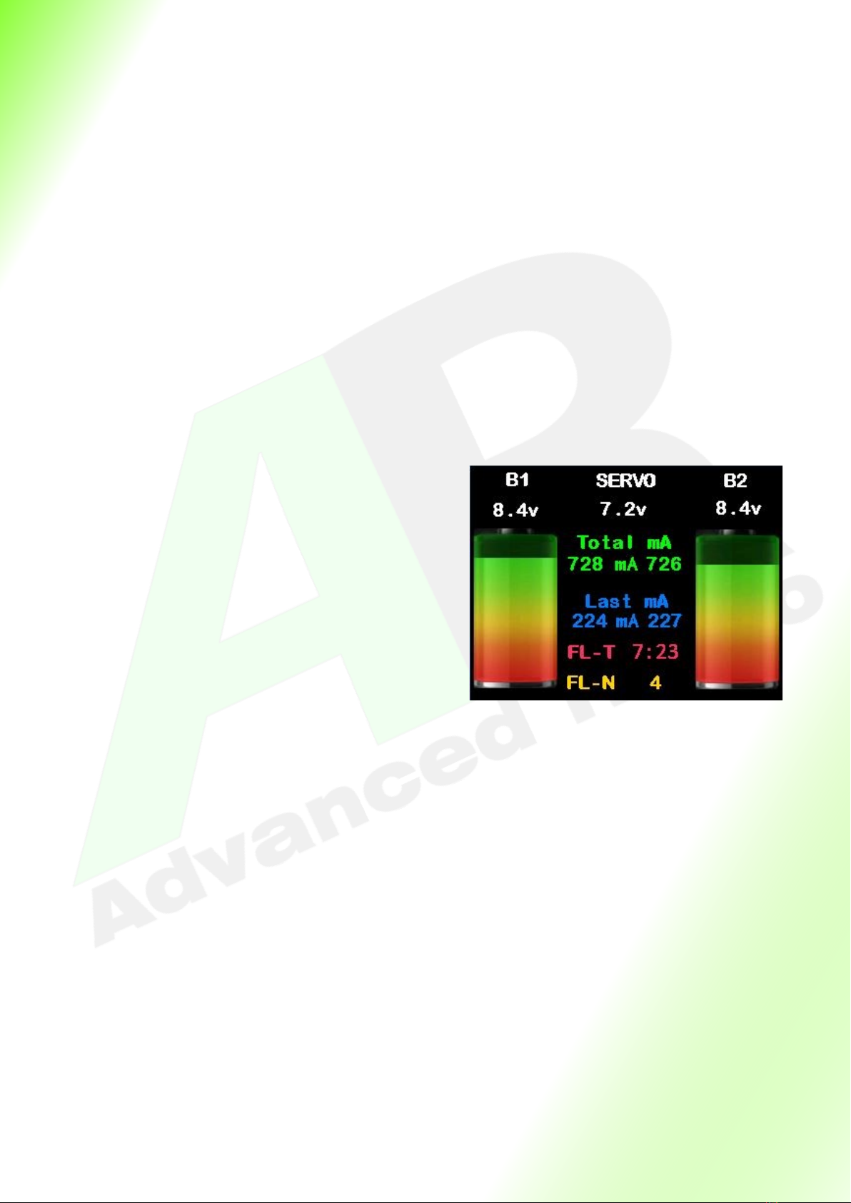
Channel Monitor Screen --------------------------------------------------------------------------------------------------- 11
Sub Trim and End Point Menu -------------------------------------------------------------------------------------------- 11
15 Point Servo Matching -------------------------------------------------------------------------------------------------- 12
Fail Safe Screen -------------------------------------------------------------------------------------------------------------- 12
First Time Baery Setup------------------------------------------------------------------------------------------------13,14
Protocol Selecon ARXL Version----------------------------------------------------------------------------------------- 15
Installing the Receivers ARXL Version ---------------------------------------------------------------------------------- 16
System Specic Receiver installaon ----------------------------------------------------------------------------------- 17
Installing Satellites Spektrum Version---------------------------------------------------------------------------------- 18
Input Channel to Servo Output Roung----------------------------------------------------------------------------19,20
Servo Sub-trim, Reversing Method 1 ----------------------------------------------------------------------------------- 21
Servo Sub-trim, Reversing Method 2 ----------------------------------------------------------------------------------- 22
15 Point Matching ----------------------------------------------------------------------------------------------------------- 23
Receiver Menu---------------------------------------------------------------------------------------------------------------- 24
Seng Fail Safe--------------------------------------------------------------------------------------------------------------- 25
Telemetry with Spektrum TM1000-------------------------------------------------------------------------------------- 26
Telemetry with SBUS2 Receivers----------------------------------------------------------------------------------------- 27
Factory Reset------------------------------------------------------------------------------------------------------------------ 28
Addional Screens----------------------------------------------------------------------------------------------------------- 29
Smooth Flite Gyro Menus-------------------------------------------------------------------------------------------------- 30
Smooth Flite Gyro Setup Wizard -----------------------------------------------------------------------------------31—34
Smooth Flite Gyro Pre Flight Checks --------------------------------------------------------------------------------35,36
Smooth Flite Advanced Stabilisaon Features -------------------------------------------------------------------36,37

3
Table Of Contents connued.
Smooth Flite Advanced Stabilisaon Features (Auto Gain Control AGC) -------------------------------------- 36
(Variable Gain Control VGC) Proporonal Mode & Aerobac Mode ------------------------------------------- 37
Smooth Flite Advanced Stabilisaon Features ( Variable Gain Control VGC)--------------------------------- 37
Smooth Flite Detailed Funcons—Channel Assignment-------------------------------------------------------38,39
Smooth Flite Detailed Funcons—Aileron ------------------------------------------------------------------------40,41
Smooth Flite Detailed Funcons—Elevator ----------------------------------------------------------------------42,43
Smooth Flite Detailed Funcons—Rudder ------------------------------------------------------------------------44,45
Smooth Flite Trim------------------------------------------------------------------------------------------------------------ 46
Smooth Flite Advanced Mixing Funcons—Crow and Flaperons, Aileron Dierenal--------------------- 47
Elevon Mixing ----------------------------------------------------------------------------------------------------------------- 48
V-Tail Mixing ------------------------------------------------------------------------------------------------------------------ 49
Gyro Assisted Steer Trim, Dual Rudder Speed Brakes -------------------------------------------------------------- 50
Vectored Thrust Switching------------------------------------------------------------------------------------------------- 51
Setup Hints—Gyro controlled Rudder and ground steering ------------------------------------------------------ 52
Setup Hints—Seng up Flaps with a single TX channel ----------------------------------------------------------- 53
Setup Hints—Elevons, Thrust Vectoring and Canards setup--------------------------------------------------54,55
Frequently Asked Quesons ---------------------------------------------------------------------------------------------- 56
Smooth Flite Specicaons------------------------------------------------------------------------------------------------ 57
Channel Roung Sheet ----------------------------------------------------------------------------------------------------- 58
Usage Statement------------------------------------------------------------------------------------------------------------- 60
Warranty and Contact Informaon ------------------------------------------------------------------------------------- 61

4
Thank you for your purchase of the Advance Radio Smooth Flite System.
The Advanced Radio Smooth Flite system was designed with Giant Scale Models in mind
and combines Power Distribuon, Flite Stabilisaon and a 16 Channel Servo control
system in the lightest package in it’s class (less than 50 grams).
In the past trimming and matching servos would take place via the transmier. This old
school thought would limit you to the number of channels available from the
transmier. With Smooth Flite these funcons have been moved to the Smooth Flite
system and in doing so brings you much more funconality and exibility in model
setup. You gain at the touch of a buon as many as 16 servo outputs that can all be
mixed, matched, sub trimmed, reversed and endpoint adjusted. The power of this new
system and thought process will become obvious as you start to use the Smooth Flite
System.
To add to this we have created much more than just a simple Gyroscope based system.
We decided to include a 3 axis gyro, accelerometer, compass and barometer into the
hardware. The combinaon of these sensors gives you much more exibility in ight
stabilisaon and that is why we called it Smooth Flite!
LETS GET STARTED — in this guide we will show you how to connect your new
Smooth Flite system, General use and setup as well as how to get the most out of the
Smooth Flite stabilisaon system. Please take the me to read & understand this guide
before installaon.
TOUCH SCREEN—The touch screen display supplied with the Smooth Flite should be
protected from vibraon. We don’t recommend mounng the Smart Screen in models
with gas powered engines.
BATTERIES—Before installaon please ensure that your baeries are fully charged. The
Smooth Flite System relies on this to know how much your model has consumed from
each pack. Smooth Flite collects this informaon and displays this as a set of baery cells
indicators on the Smart Screen. NEVER FLY WITH BATTERY PACKS THAT HAVE 35% OR
LESS CAPACITY (RED ZONE ON THE BATTERY INDICATOR). Doing so may put your model
at risk.
RECEIVER INSTALLATION—Some receivers don’t oer protecon against incorrect
polarity or pin oset. IT IS IMPORTANT that you observe correct polarity and pins when
connecng the receivers to the Smooth Flite system.

5
Features:
• Built-in Baery Guard Technology. The Smooth Flite constantly monitors baery
voltage and current draw and displays this on the Smart Screen display.
• Works with single or dual baery conguraon. *Recommended with dual baery.
• Works with all major baery chemistries. LiFe. LiPo, Lion, NiMh, NiCD. Baery voltage
range can be from 6volts to 8.4volts.
• Full Dual Baery Redundancy - If one baery fails the other baery takes full control.
• Dual receiver redundancy
• Up to 16 input channels (depending on transmier capability)
• 16 fully assignable and programmable servo outputs.
• Easy-to-use pre-routed servo roung.
• Independent servo reverse on all channels.
• Sub Trim and end point (3 point) matching on all channels.
• Advanced 15 point matching on all channels
• Maximum Baery Power Balancing – Using dual baery perfect diode technology.
• Proprietary Smooth Flite System with 3 axis Gyro, Accelerometer and Barometer.
Included Items:
1 x Live feedback touch screen Smart display
1 x Smooth Flite power distribuon module.
1 x Power LED
3 x Receiver cables
Oponal Items:
Pin Flag switch with Advance Radio Flag
Remote FOB Switch with Advance Radio Flag
Magnec Switch with Advance Radio Flag
2 x Receivers

6
Installaon and Mounng Instrucons
In this secon we will explain how to mount both the Smooth Flite and the Smart Display.
The Advanced Radio Smart System gives you the choice of mounng the Smart Screen in
the Model or leaving it disconnected for normal ying. The Smooth Flite will operate in
normal ying mode without the Smart Screen Connected.
Smart Screen Mounng
If your model is a gas powered and has a high level of vibraon then we don’t
recommend mounng the screen in the model unless you provide a high level of
vibraon damping when mounng the screen.
If your model provides a low vibraon environment (Turbine, Sail Plane, Electric model)
then hard mounng of the Smart Screen is possible.
The Smooth Flite provides downlink telemetry so it is not necessary to mount the
Smart Screen in the model to view baery data.
Mounng the Smooth Flite System
The Smooth Flite is supplied with 4 rubber shock mounts in the base plate, similar to rubber
mounts on servos, these provide shock mounng for the Smooth Flite.

7
Mounng the Smart Display
To save weight the Smart Screen is not required for normal ying usage. It is only required
for programming the Smooth Flite.
Should you wish to mount the Smart Screen in the model for quick baery checks etc then
we recommend 2 opons of mounng the Smart Screen display.
NOTE: Whichever method of mounng you choose, ensure the cable that comes out of
the Smart Screen Display is not crushed in any way. Doing so will reduce the longevity of
the cables.
Opon 2. For hard mounng. The screen case has 2 eyelet holes on each edge of the screen.
If you are mounng the screen in a scale cockpit, or in a non vibraon model. (e.g. Turbine)
these holes can be used to ax the Smart Display.
Simply place the Smart Display where you wish to mount it. Holding it in place, make a dot
using a pen or pencil in each eyelet hole. Removing the screen, drill a hole where you placed
the dots.
Now simply screw the Smart Display in place.
NOTE: Hard mounng the Smart Display provides lile to NO protecon against vibraon.
Use this method if you are using a non vibraon model or ONLY where there is lile to no
vibraon. AVOID MOUNTING IN HIGH VIBRATION AREAS.
Opon 1. Using 3M Velcro adhesives, you can mount the back of the screen to a surface.
NOTE: This is a semi hard mount, and will provide a good resistance to vibraon. AVOID
MOUNTING IN HIGH VIBRATION AREAS. VIBRATION DAMAGE IS NOT COVERED UNDER
WARRANTY. Clean both the back of the Smart Screen and surface that it is being mounted
on. Place 3M dots/tape each side of the cable. Trimming as necessary.
IMPORTANT: DO NOT APPLY FORCE DIRECTLY ONTO THE SCREEN
Press on the black case around the screen to ensure it is secure.

8
General Usage and Screen Informaon
Important: The Smart Screen Display supplied with the Smooth Flite is a touch screen
display. It is used in both setup and provides feedback to the user about baery voltage and
milliamps used. The screen can be mounted in a model for quick and easy use. However the
Smooth Flite will operate during normal ying mode without the Smart Screen connected.
Main Smart Screen Display
Baery 1 (B1) and Baery 2 (B2)
Shows input voltage of both baery packs.
Servo
Shows Regulated voltage to servos
Total mA
Shows total milliamps since last charge.
Press here to enter the Main Menu
Last mA
Shows milliamps used since model was last powered up
and resets when model is turned o. Press here to reset
ight mer and Last mA.
FL-T
Flight mer since model was turned on. The mer only
operates while on the main screen.
FL-N
Flight number since reset. Gives an indicaon of number
of ights on the models airframe.
Baery Indicators
Shows the remaining capacity in the baeries from 100%
- 0%. NEVER FLY IF THE INDICATORS ARE IN THE RED.
Below is an overview of each screen on the Smooth Flite

9
Main Menu
Return
Returns back to the previous screen.
Power
Press here to go to the baery setup and reset
menu.
Monitor
Press here to go to servo programming menu.
I/O Roung
Pressing here will take you to the channel
roung screen.
Servo Match
Pressing here will take you to the 3 point and 15
point servo matching screen,
Receiver
Pressing here will take you to the receiver and
frame rate monitor screen.
System
Pressing here will take you to the system page
which contains credits and system informaon
Smooth Flite
Pressing here will take you to the Smooth Flite
page.
Power Setup Screen
Return
Takes you back to the previous screen.
RES-mA
Resets total mA used. Please ensure both packs
are FULLY charged before you reset.
RES-FLT
Resets ight counter and mer to zero. Use this
feature mostly when installing in a new airframe
or before the maiden ight.
Bat Capacity mA
Shows the capacity of the baeries you are
using. We will go through how to set this in the
First Time Setup secon on page 10.

10
Servo Matching screen
Return
Takes you back to the previous screen.
S01—S16
Pressing any of these buons will take you
to the servo matching page for the
corresponding servo output on the Smooth
Flite. Here you can match the
servos with the 3 point and 15 point
matching.
I/O Roung Screen
Save
Takes you back to the previous screen and
saves your roung choices.
- and + buons
Changes the input Channel from 1 to 16
Note: you can only assign servos to channels
that are available from your Receiver.
Example: you can not assign a servo to
channel 16 when using a 10 channel radio
S01 to S16
These buons correspond to the outputs on
the Smooth Flite RRS.
They have 3 colours,
Green = they are assigned to the current re-
ceiver channel.
Blue = they are not assigned to any receiver
channel.
Grey = they have been assigned to a dierent
receiver channel and cannot be selected for
this channel
Indice
Altri manuali AR Unità di controllo
Manuali Unità di controllo popolari di altre marche

Festo
Festo Compact Performance CP-FB6-E Manuale elenco delle parti

Elo TouchSystems
Elo TouchSystems DMS-SA19P-EXTME Manuale utente

JS Automation
JS Automation MPC3034A Manuale utente

JAUDT
JAUDT SW GII 6406 Series Guida rapida

Spektrum
Spektrum Air Module System Manuale utente

BOC Edwards
BOC Edwards Q Series Manuale utente


